
Related Manuals for Vaisala HUMICAP HMD70U


Summary of Contents for Vaisala HUMICAP HMD70U
- Page 1 USER'S GUIDE ® Vaisala HUMICAP Humidity and Temperature Transmitters HMD70U/Y U303EN11...
- Page 2 The contents are subject to change without prior notice. Please observe that this manual does not create any legally binding obligations for Vaisala towards the customer or end user. All legally binding commitments and agreements are included exclusively in the applicable supply contract or Conditions of...
-
Page 3: Table Of Contents
HMD70U/Y Transmitters U303en-1.1 Operating Manual Contents PRODUCT DESCRIPTION ....................1 TO BE NOTED WHEN MEASURING HUMIDITY ..............2 INSTALLATION........................3 Selecting the place of installation ................3 Mounting ........................3 Grounding ........................ 4 Electrical connections and installation of the current module ......5 3.4.1... - Page 4 HMD70U/Y Transmitters Operating Manual U303en-1.1 This page intentionally left blank. 1997-07-31...
-
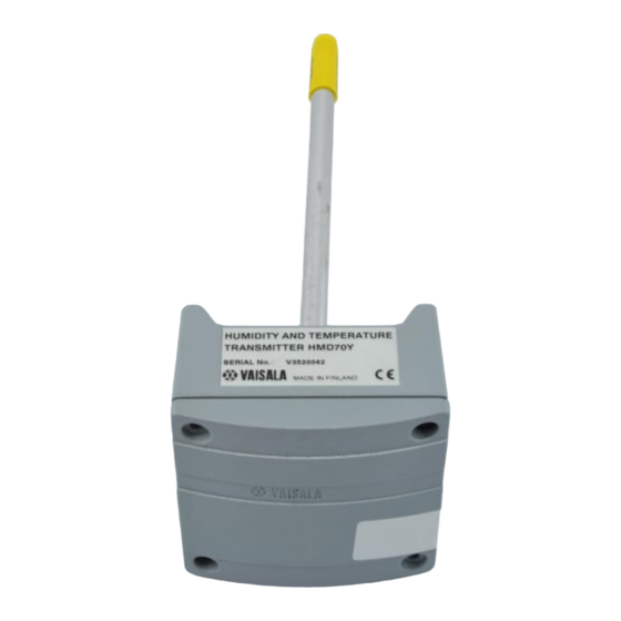
Page 5: Product Description
(HMD70U) and for the measurement of humidity and temperature (HMD70Y). The HMD70U/Y transmitters are easy to install and maintain: the electronics can be disconnected without dismantling the installation. One point calibration is easily performed with the HMI41 indicator and the calibration cable 19116ZZ. -
Page 6: To Be Noted When Measuring Humidity
HMD70U/Y Transmitters Operating Manual U303en-1.1 TO BE NOTED WHEN MEASURING HUMIDITY In the measurement of humidity and especially in calibration, it is essential that the temperature equilibrium is reached. Even a slight difference in the temperature between the measured object and the sensor causes an error. For example, at +20 C (+ 68 F) and 50 %RH, a temperature difference of +1 C between the measured object and the sensor causes an error of +3 %RH. -
Page 7: Installation
Mount the transmitter with two screws. Place the drilling template on the duct surface and drill the holes as indicated. Remember to drill an additional hole for calibration purposes. 62 (2.44) 250 (9.84) 100 (3.94) Ø 12 (0.47) <<< Mounting hole 82 (3.23) Figure 3.2 Dimensions of the HMD70U/Y (in mm) 1997-07-31... -
Page 8: Grounding
HMD70U/Y Transmitters Operating Manual U303en-1.1 Grounding Open the lid and mount the cable bushing set 18941HM. Do the grounding according to Figure 3.3. When connecting the signal cable to the transmitter housing, fold the cable braid between the brass disk in order to achieve the best possible EMC performance. -
Page 9: Electrical Connections And Installation Of The Current Module
HMD70U/Y Transmitters U303en-1.1 Operating Manual Electrical connections and installation of the current module Figure 3.4 shows the electrical connections and the installation of the current module. INSTALLATION OF THE CURRENT MODULE 18945HM OUTPUT SELECTIONS 1. Take off the jumpers 0...1V Connect the module;... -
Page 10: Connection To An Ac Supply
3.4.1 Connection to an AC supply The HMD70U/Y transmitters can also be connected to an AC supply without an external rectifier. However, when more than one transmitter is connected to one AC transformer, a common loop is formed and there is an increased risk of a short-circuit. -
Page 11: Electronics
HMD70U/Y Transmitters U303en-1.1 Operating Manual Electronics TO REMOVE THE SENSOR HEAD: 1. Open the lid 2. Disconnect the screw terminal 3. Open the screws (2 pcs) 4. Pull out carefully SCREW TERMINAL TO REINSTALL THE SENSOR HEAD: SCREWS 1. Push in the sensor head 2. -
Page 12: Calibration
HMI41 indicator equipped with an appropriate probe and optional calibration cable. If adjustment is needed, use the one-point calibration potentiometer. If you prefer to calibrate the HMD70U/Y transmitters against saturated salt solutions, use LiCl (11 %RH) and NaCl (75 %RH) solutions. -
Page 13: Calibration Table
HMD70U/Y Transmitters U303en-1.1 Operating Manual Calibration table Temperature °C °F LiCl 11.3 11.3 11.3 11.3 4...20 mA 5.81 5.81 5.81 5.81 0...20 mA 2.26 2.26 2.26 2.26 0...1 V 0.113 0.113 0.113 0.113 0...5 V 0.565 0.565 0.565 0.565 0...10 V 1.13... -
Page 14: Technical Data
HMD70U/Y Transmitters Operating Manual U303en-1.1 TECHNICAL DATA Relative humidity Measurement range 0...100 %RH Accuracy at 20 C: % R H 1 0 0 Temperature dependence: - 2 0 - 1 0 ° C -0.5 -1.0 -1.5 -2.0 Response time (90%) at +20 C in still air... -
Page 15: General
HMD70U/Y Transmitters U303en-1.1 Operating Manual General Supply voltage range depends on the selected output signal. When AC supply is used, an isolated source is recommended. The current outputs require an optional output module, part no.18945HM. 0...1 V 10...35 V 9...24 V 0...5 V... -
Page 16: Electromagnetic Compatibility
ENV50204:1995 criteria A (* additional test) GUARANTEE Vaisala issues a guarantee for the material and workmanship of this product under normal operating conditions for one year from the date of delivery. Exceptional operating conditions, damage due to careless handling or misapplication will void the guarantee. - Page 18 www.vaisala.com...