Table of Contents
Advertisement
Quick Links
Advertisement
Table of Contents

Related Manuals for Vaisala DRYCAP DMT143


Summary of Contents for Vaisala DRYCAP DMT143
- Page 1 USER'S GUIDE ® Vaisala DRYCAP Dewpoint Transmitter DMT143 M211435EN-D...
- Page 2 English versions are applicable, not the translations. The contents of this manual are subject to change without prior notice. This manual does not create any legally binding obligations for Vaisala towards customers or end users. All legally binding obligations and agreements are included exclusively in the applicable supply contract or the General Conditions of Sale and General Conditions of Service of Vaisala.
-
Page 3: Table Of Contents
Alarm LED ................18 CHAPTER 4 INSTALLATION .................... 19 Transmitter Configuration Before Installation ....19 Selecting the Location ............20 Installing the Transmitter ............20 Wiring ..................22 Power Supply Requirements ..........23 Sampling from a Process ............26 VAISALA _________________________________________________________________________ 1... - Page 4 USER'S GUIDE ____________________________________________________________________ Sampling Accessories ............26 DMT242SC Sampling Cell ..........26 DMT242SC2 Sampling Cell with Swagelok Connectors ..26 DSC74 Sampling Cell with Quick Connector and Leak Screw ..................... 27 DSC74B Two-Pressure Sampling Cell ........ 28 DSC74C Two-Pressure Sampling Cell with Coil .... 30 DM240FA Duct Installation Flange ........
- Page 5 Error Messages ..............64 Unknown Serial Settings ............64 Technical Support ..............65 Product Returns ..............65 CHAPTER 8 TECHNICAL DATA ..................67 Specifications ................. 67 Spare Parts and Accessories ..........70 Dimensions in mm ..............71 VAISALA _________________________________________________________________________ 3...
- Page 6 USER'S GUIDE ____________________________________________________________________ List of Figures Figure 1 DMT143 Parts – Model with ISO Thread ......... 11 Figure 2 DMT143 Parts – Model with NPT Thread ........ 12 Figure 3 Nokeval 301 Loop-Powered Display ........13 Figure 4 DMT143 Startup Sequence ............17 Figure 5 Removing the Transport Protection Cap ........
-
Page 7: Chapter 1 General Information
- Chapter 6, Maintenance, provides information that is needed in basic maintenance of the DMT143. - Chapter 7, Troubleshooting, describes common problems, their probable causes and remedies, and provides contact information for technical support. - Chapter 8, Technical Data, provides the technical data of the DMT143. VAISALA _________________________________________________________________________ 5... -
Page 8: Version Information
USER'S GUIDE ____________________________________________________________________ Version Information Table 1 Manual Revisions Manual Code Description M211435EN-D June 2013. This manual. Updated wiring instructions. M211435EN-C January 2013. Previous version. Updated command descriptions for ASEL, FORM, SERI, and SDELAY commands. M211435EN-B June 2012. Updated section Alarm LED on page 18. -
Page 9: Safety
ESD Protection Electrostatic Discharge (ESD) can cause immediate or latent damage to electronic circuits. Vaisala products are adequately protected against ESD for their intended use. It is possible to damage the product, however, by delivering electrostatic discharges when touching the exposed connectors on the back of the product. -
Page 10: Regulatory Compliances
All other trademarks are the property of their respective owners. License Agreement All rights to any software are held by Vaisala or third parties. The customer is allowed to use the software only to the extent that is provided by the applicable supply contract or Software License Agreement. -
Page 11: Chapter 2 Product Overview
For this calculation to provide accurate results, it is important to have the correct pressure setting stored in the transmitter. This setting is specified on the order form, and it can be changed using the RS-485 line or DM70 hand-held dewpoint meter. VAISALA _________________________________________________________________________ 9... -
Page 12: Basic Features And Options
USER'S GUIDE ____________________________________________________________________ Basic Features and Options - Dewpoint measurement range -60 ... +60 °C (-76 ... +140 °F). - Dewpoint measurement accuracy up to ±2 °C (±5.4 °F) T in air or N - Operating pressure range 0 ... 50 bar (725 psia). -
Page 13: Transmitter Parts
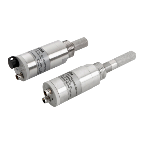
Transmitter body. Type label is applied here. Digital output: non-isolated RS-485. Alarm LED. Analog output. Sealing ring. Must be used with the G1/2” ISO228/1 connection thread. 24 mm nut. Connection thread: G1/2" ISO228/1. ® DRYCAP sensor protected with sintered filter. VAISALA ________________________________________________________________________ 11... -
Page 14: Model With Npt Thread
USER'S GUIDE ____________________________________________________________________ Model with NPT Thread 1202-121 Figure 2 DMT143 Parts – Model with NPT Thread The following numbers refer to Figure 1 on page 11: Transmitter body. Type label is applied here. Digital output: non-isolated RS-485. Alarm LED. Analog output. -
Page 15: Loop-Powered Display
Figure 3 Nokeval 301 Loop-Powered Display The loop resistance of the display must be included in the loop resistance NOTE calculation for the complete current loop. For the loop resistance of the display, refer to the manufacturer’s documentation. VAISALA ________________________________________________________________________ 13... -
Page 16: Connection Cables
USER'S GUIDE ____________________________________________________________________ Connection Cables Vaisala supplies shielded cables with M8 female straight threaded connector. Standard cables are available in four lengths: - 0.3 m (1.0 ft) - 3 m (9.8 ft) - 5 m (16.4 ft) - 10 m (32.8 ft) Heavy duty cables are available in two lengths: - 1.5 m (4.9 ft) -
Page 17: Functional Description
Sensor purge is also an automatic procedure that minimizes the drift at the wet end readings of the dewpoint measurement. Sensor purge is performed once a day or when the power is switched on. The sensor is heated for several minutes which will then evaporate all excess VAISALA ________________________________________________________________________ 15... -
Page 18: Sensor Warming In High Humidities
USER'S GUIDE ____________________________________________________________________ molecules out of the sensor polymer. This, together with the auto- calibration results in a very small drift of the sensor due to the very linear behaviour of the polymer technology. During the sensor purge the transmitter outputs the T value prior to the procedure. -
Page 19: Dmt143 Startup Sequence
** Autocal will repeat every 60 minutes (is postponed if environment is not suitable) 1202-115 Figure 4 DMT143 Startup Sequence The transmitter always performs this sequence when starting up. Keep NOTE the transmitter continuously powered to optimize its measurement performance and availability. VAISALA ________________________________________________________________________ 17... -
Page 20: Alarm Led
USER'S GUIDE ____________________________________________________________________ Alarm LED The alarm LED at the back of the transmitter provides a visual indication of the transmitter’s status. The alarm LED functionality is preset at the factory according to order form. You can configure it as follows: - You can change the alarm limit using the DM70 hand-held dewpoint meter. -
Page 21: Chapter 4 Installation
(range 0 ... 255) and set their serial operation mode to POLL. The default serial line settings may not be right for your RS-485 line. You may need to change the transmitter’s serial output format to suit your needs. VAISALA ________________________________________________________________________ 19... -
Page 22: Selecting The Location
Sampling from the process is easy by using Vaisala sampling cell options; see section Sampling Accessories on page 26. The DMT143 is light in weight, which means that it can be installed in a sample pipeline in the sampling cells without the need of any additional mechanical support. -
Page 23: Figure 6 Installing The Transmitter With Sealing Ring
Wrench size is 24 mm for ISO threaded transmitter, 30 mm for NPT threaded model. 1202-124 Figure 7 Tightening with a Wrench Connect the signal and power cable to the DMT143. Refer to the following sections for wiring instructions and power supply requirements. VAISALA ________________________________________________________________________ 21... -
Page 24: Wiring
USER'S GUIDE ____________________________________________________________________ Wiring CAUTION The power supply lines are internally connected. You can use either one of them, but do not connect more than one supply voltage in permanent installations. Temporary simultaneous use with the USB service cable or DM70 hand-held dewpoint meter (which also provide power) is OK. -
Page 25: Power Supply Requirements
The DMT143 can be powered by the MI70 indicator or the USB service cable. You can plug in the MI70 indicator or the USB service cable to the digital port while the transmitter is powered from the analog port. VAISALA ________________________________________________________________________ 23... -
Page 26: Figure 11 Example Of Current Consumption During Purge
USER'S GUIDE ____________________________________________________________________ Figure 11 below shows a typical duty cycle during sensor purge at room temperature with 24 VDC supply voltage. Sensor purge current varies with supply voltage and operating temperature. The peak value is the highest in the lowest temperature. 1203-129 Figure 11 Example of Current Consumption During Purge... -
Page 27: Figure 12 Example Of Current Consumption During Auto-Calibration
Figure 12 below shows a typical duty cycle during auto-calibration at room temperature with 24 VDC supply voltage. Also the auto-calibration current varies with supply voltage and operating temperature. 1203-130 Figure 12 Example of Current Consumption During Auto- Calibration VAISALA ________________________________________________________________________ 25... -
Page 28: Sampling From A Process
Make sure there is sufficient flow of gas to the sensor (for example, 1 l/min) to give a representative sample. You can use the Vaisala Humidity Calculator to simulate the effect of pressure change to dewpoint. The Humidity Calculator can be found at: www.vaisala.com/humiditycalculator... -
Page 29: Dsc74 Sampling Cell With Quick Connector And Leak Screw
This allows for easy installation and detachment of the dewpoint transmitter without having to shut down the process. Alternative ways to connect are through the two different thread adapters (G3/8" to G1/2" and G3/8" to G1/4" ISO) that are supplied with each DSC74 unit. VAISALA ________________________________________________________________________ 27... -
Page 30: Dsc74B Two-Pressure Sampling Cell
The maximum flow can be increased, if needed, by removing the leak screw and adjusting the flow manually with the valve. Harmful gases can be recovered by connecting a collection system at the outlet (not available from Vaisala). 28 ___________________________________________________________________ M211435EN-D... -
Page 31: Figure 15 Dsc74B
- Connection part with a needle valve and an integrated leak screw - Reducing Nipple (thread adapter), G3/8" - G1/2" - Reducing Adapter (thread adapter), G3/8" - G1/4" 0510-032 Figure 15 DSC74B where Gas goes in Gas comes out 0510-033 Figure 16 Removing the Leak Screw VAISALA ________________________________________________________________________ 29... -
Page 32: Dsc74C Two-Pressure Sampling Cell With Coil
USER'S GUIDE ____________________________________________________________________ DSC74C Two-Pressure Sampling Cell with Coil The DSC74C with an outlet coil is designed for the most critical measurements at atmospheric pressure. In the DSC74C, the coil is connected to the sampling cell outlet to protect the sensor from ambient humidity disturbing the measurement. -
Page 33: Figure 18 Alternative Assembly Of Dsc74C (For Tight Spaces)
Alternative Assembly of DSC74C (for Tight Spaces) where Gas comes out Coil Thread, max. size 7 mm Gas goes in Valve The thread size cannot exceed 7 mm. Use the provided adapter to avoid damage to the transmitter. VAISALA ________________________________________________________________________ 31... -
Page 34: Dm240Fa Duct Installation Flange
1202-125 Figure 19 DM240FA with DMT143 where Measured gas DMT143 transmitter DM240FA flange (thread G1/2” ISO228/1) Recommended additional hole (plugged) for T field check reference measurement probe (for example, Vaisala DM70) 32 ___________________________________________________________________ M211435EN-D... -
Page 35: Chapter 5 Operation
- In RUN mode a measurement output starts immediately. - In POLL mode the transmitter does not output anything after power- For a description of the modes, see section Set Serial Line Operating Mode on page 53. VAISALA ________________________________________________________________________ 33... -
Page 36: Operation With Dm70 Hand-Held Dewpoint Meter
USER'S GUIDE ____________________________________________________________________ Operation with DM70 Hand-Held Dewpoint Meter You can connect the DMT143 to the MI70 indicator (the measurement display that is included in the DM70 package) using the MI70 connection cable (order code 219980SP). This allows you to view and use the measurement data with the MI70 indicator. -
Page 37: Serial Communication
There is no reason to uninstall the driver for normal use. However, if you wish to remove the driver files and all Vaisala USB cable devices, you can do so by uninstalling the entry for Vaisala USB Instrument Driver from the Programs and Features menu in the Windows Control Panel. -
Page 38: Terminal Application Settings
Serial line to connect to field. Note: You can check which port the USB cable is using with the Vaisala USB Instrument Finder program that has been installed in the Windows Start menu. Check that the other serial settings are correct for your connection, and change if necessary. -
Page 39: Figure 21 Putty Terminal Application
Chapter 5 _________________________________________________________________ Operation 0807-004 Figure 21 PuTTY Terminal Application VAISALA ________________________________________________________________________ 37... -
Page 40: List Of Serial Commands
USER'S GUIDE ____________________________________________________________________ List of Serial Commands All commands can be issued either in uppercase or lowercase. In the command examples, the keyboard input by the user is in bold type. The notation <cr> refers to pressing the carriage return (Enter) key on your computer keyboard. -
Page 41: Device Information
Baud P D S: 19200 N 8 1 Output interval: Serial delay Address Pressure 1.013 bar Filter 0.100 Show Analog Output Mode Use the AMODE command to show the analog output mode: AMODE<cr> Example: amode Ch1 output : 4 ... 20 mA VAISALA ________________________________________________________________________ 39... -
Page 42: Show Firmware Version
DMT143 1.0.2 Show Firmware Information SYSTEM<cr> Example: system Device Name : DMT143 Copyright : Copyright (c) Vaisala Oyj 2012. All rights reserved. SW Name : DMT143 SW date : 2012-05-10 SW version : 1.0.2 Show Currently Active Errors Use the ERRS command to display the currently active transmitter error messages. -
Page 43: Show Command List
Use the HELP command to show a list serial commands: HELP<cr> Example: help ADDR AERR ALARM AMODE AOVER AOUT ASEL ATEST CLOSE ERRS FILT FORM FRESTORE HELP INTV OPEN PRES RESET SDELAY SEND SERI SMODE SNUM SYSTEM TIME UNIT VERS XPRES VAISALA ________________________________________________________________________ 41... -
Page 44: Configuring Analog Output
= Parameter that is output on analog channel. Available parameters are TDF, TDFA, H2O. If the transmitter has been ordered from Vaisala with a relative humidity output on the analog channel, also parameter RH is available. lowlimit = Lower limit of parameter scaling. -
Page 45: Set Analog Output Error Notification
Ch1 error out 20.000 mA The error output value is displayed only when there are minor electrical NOTE faults such as a sensor damage. When there is a severe device malfunction, the error output value is not necessarily shown. VAISALA ________________________________________________________________________ 43... -
Page 46: Extend Analog Output Range
Analog output type determines if the value is V or mA. The command output shows the test value of the analog output as well as diagnostic information that may be useful to Vaisala Service if there is a problem with the analog output. -
Page 47: Enable Or Disable Analog Output
922 ppm Tdf= 16.97 'F Tdfatm= -5.96 'F H2O= 918 ppm Outputting the results continues in intervals issued with the command INTV until stopped. Stop Measurement Output You can stop the measurement output by pressing the ESC key. VAISALA ________________________________________________________________________ 45... -
Page 48: Set Output Interval
USER'S GUIDE ____________________________________________________________________ Set Output Interval Use the INTV command to change the output interval of the automatically repeating measurement messages. The measurement messages are repeated in the RUN mode, or after the R command has been given. INTV [n xxx]<cr> where time interval, range 0 ... -
Page 49: Configuring Measurement Parameters
#002 3.2 "Tdf=" Tdf U3 6.0 "H2O=" H2O " " U5 #003 Output example (ASCII codes not visible here): Tdf= -9.57'C H2O= 2671 ppm Tdf= -9.59'C H2O= 2666 ppm Tdf= -9.61'C H2O= 2662 ppm Tdf= -9.62'C H2O= 2660 ppm VAISALA ________________________________________________________________________ 47... -
Page 50: Table 8 Form Command Parameters
Dewpoint/frost point temperature, Tdfa converted to atmospheric pressure ppm moisture, by volume Relative humidity* * RH is available only if transmitter has been ordered from Vaisala with a relative humidity output on the analog channel. Table 9 FORM Command Modifiers Modifier... -
Page 51: Set Measured Gas Type
1.0 = No filtering, latest measurement is output without averaging 0.5 = Average of last two measurements 0.1 = Average of ca. 16 measurements (default) Example (show current setting): filt Filter 0.100 Example (set filtering to 0.5): filt 0.5 Filter 0.500 VAISALA ________________________________________________________________________ 49... -
Page 52: Set Pressure Compensation Value
USER'S GUIDE ____________________________________________________________________ Set Pressure Compensation Value The pressure of the measured system must be known for accurate dewpoint and ppm measurement. The pressure compensation value has been set at the factory according to the order form. You can view and set a new value using the PRES command. -
Page 53: Select Unit
Tdf offset: 0.00000000E+00 Tdf gain 1.00000000E+00 Example (shows that a -1.2 °C Tdf offset has been applied by the user): RH offset : 0.00000000E+00 RH gain 1.00000000E+00 offset : 0.00000000E+00 gain 1.00000000E+00 Tdf offset: -1.20000000E+00 Tdf gain 1.00000000E+00 VAISALA ________________________________________________________________________ 51... -
Page 54: Set User Adjustment Parameters
This command is provided primarily for applying an offset to the Tdf measurement. Do not adjust the other parameters unless instructed to do so by a Vaisala Service Center. LI<cr> After entering the command, you will be prompted to enter new values one at a time. -
Page 55: Configuring Serial Line Operation
OPEN command. Use with RS-485 buses where multiple transmitters can share the same line. Selected output mode will be activated at next reset or power up. Example: smode poll Serial mode POLL VAISALA ________________________________________________________________________ 53... -
Page 56: Set Serial Line Settings
USER'S GUIDE ____________________________________________________________________ Set Serial Line Settings Use the SERI command to set the serial line settings. The new settings will be taken into use when the transmitter is reset or powered up. Note that changing the serial line settings will slightly alter how the transmitter works with the MI70 indicator. -
Page 57: Set Serial Line Response Time
Example (target transmitter in POLL mode, with address 5): open 5 DMT143 5 line opened for operator commands Closing the Connection to a Transmitter in POLL Mode The CLOSE command closes the connection to a transmitter. CLOSE<cr> Example: close line closed VAISALA ________________________________________________________________________ 55... -
Page 58: Configure The Alarm Led
USER'S GUIDE ____________________________________________________________________ Configure the Alarm LED Use the ALARM command to configure the alarm LED functionality. For more information on the LED, see section Alarm LED on page 18. ALARM [LED] [Alarm] [Level]<cr> where = Enable or disable the entire LED functionality. Allowed values: ON - Enable the LED functionality. -
Page 59: Show Transmitter Uptime
SMODE command. Restore Factory Settings Use the FRESTORE command to restore the transmitter to its factory configuration. All user settings will be lost. FRESTORE<cr> After using the FRESTORE command, reset the transmitter using the NOTE RESET command. VAISALA ________________________________________________________________________ 57... - Page 60 USER'S GUIDE ____________________________________________________________________ This page intentionally left blank. 58 ___________________________________________________________________ M211435EN-D...
-
Page 61: Chapter 6 Maintenance
DM70 hand-held dewpoint meter. If the field check indicates that the DMT143 is not within its accuracy specifications, contact a Vaisala Service Center or your local Vaisala representative to have the DMT143 adjusted. VAISALA ________________________________________________________________________ 59... -
Page 62: Changing The Filter
This way, the chamber can be pressurized although the transmitter is not in place. Plugs are available from Vaisala for ISO and NPT threaded connections. When replacing the filter, wear clean gloves to avoid depositing dirt or oil on the filter. -
Page 63: Field Check Using The Dm70 Hand-Held Dewpoint Meter
- You also need a connection cable (Vaisala order code: 219980SP) to connect the DMT143 to the MI70 indicator. In the procedure below, the readings of the transmitter and the reference NOTE probe are checked simultaneously. -
Page 64: Repair Maintenance
If there is a problem with your transmitter that you are unable to solve yourself or with the help of the Vaisala Helpdesk, contact a Vaisala Service Center. In case of mechanical or electrical failure, the Service Center may replace the transmitter with a new one. -
Page 65: Chapter 7 Troubleshooting
FRESTORE command. If you are unable to solve your problem with the transmitter, contact Vaisala technical support. See section Technical Support on page 65. Table 12... -
Page 66: Error Messages
Error Messages Error Message Possible Cause and Solution ® T MEAS error DRYCAP sensor damaged or missing. Contact a Vaisala service F meas error center. Voltage error Supply voltage out of range. Check and correct. Voltage too low error Voltage too low for mA output... -
Page 67: Technical Support
Chapter 7 ____________________________________________________________ Troubleshooting Technical Support For technical questions, contact the Vaisala technical support by e-mail at helpdesk@vaisala.com. Provide at least the following supporting information: - Name and model of the product in question - Serial number of the product... - Page 68 USER'S GUIDE ____________________________________________________________________ This page intentionally left blank. 66 ___________________________________________________________________ M211435EN-D...
-
Page 69: Chapter 8 Technical Data
Measurement range 10 ... 40 000 ppm (typical) Accuracy at +20 °C (+68 °F), 1 bar pressure 1 ppm + 20% of reading * When the dewpoint is below 0 °C (32 °F), the transmitter outputs frostpoint. VAISALA ________________________________________________________________________ 67... -
Page 70: Figure 24 Dewpoint Accuracy Vs. Measurement Conditions
0 ... 1 V/5 V 1 ... 5 V Resolution for current output 0.002 mA Resolution for voltage output 0.3 mV Typical temperature dependence 0.005% of span / °C Digital output RS-485, non-isolated Vaisala Industrial Protocol Connector 4-pin M8 (IEC 60947-5-2) 68 ___________________________________________________________________ M211435EN-D... -
Page 71: Table 17 General
ISO G1/2” threaded version 90g (3.2 oz) NPT 1/2" threaded version 100 g (3.5 oz) Electromagnetic compatibility Complies with EMC standard EN61326-1, Electrical equipment for measurement, control and laboratory use - EMC requirements - for use in industrial locations. VAISALA ________________________________________________________________________ 69... -
Page 72: Spare Parts And Accessories
USER'S GUIDE ____________________________________________________________________ Spare Parts and Accessories Table 18 Spare Parts and Accessories for DMT143 Description Order Code Connection cable for MI70 Hand-Held Indicator 219980SP USB service cable 219690 Loop-powered external display, Nokeval 301 226476 Loop-powered external display, Nokeval 302 (with alarm relays) 234759 Installation flange ISO ½... -
Page 73: Dimensions In Mm
Chapter 8 _____________________________________________________________ Technical Data Dimensions in mm AW24 G1/2" ISO228/1 22.5 91.6 1202-130 Figure 25 DMT143 Dimensions – Model With ISO Thread AW30 NPT1/2" 22.5 49.1 91.6 1202-131 Figure 26 DMT143 Dimensions – Model With NPT Thread VAISALA ________________________________________________________________________ 71... - Page 74 *M211435EN*...