Vaisala HUMICAP HMW90 SERIES User Manual
Humidity and temperature transmitter
Hide thumbs
Also See for HUMICAP HMW90 SERIES:
- Quick manual (118 pages) ,
- User manual (66 pages) ,
- Technical reference manual (20 pages)

Related Manuals for Vaisala HUMICAP HMW90 SERIES


Summary of Contents for Vaisala HUMICAP HMW90 SERIES
- Page 1 USER'S GUIDE ® Vaisala HUMICAP Humidity and Temperature Transmitters HMW90 Series M211399EN-F...
- Page 2 English versions are applicable, not the translations. The contents of this manual are subject to change without prior notice. This manual does not create any legally binding obligations for Vaisala towards customers or end users. All legally binding obligations and agreements are included exclusively in the applicable supply contract or the General Conditions of Sale and General Conditions of Service of Vaisala.
-
Page 3: Table Of Contents
Wiring HMW92 ..............29 Wiring HMW93 ..............30 Wiring TMW92..............31 Wiring TMW93..............31 Connecting a Common AC Power Supply to Several Transmitters ................ 32 Wiring HMW95 ..............33 Connecting Several Transmitters on Same RS-485 Line (HMW95) ........... 33 VAISALA _________________________________________________________________________ 1... - Page 4 User's Guide _______________________________________________________________________ CHAPTER 4 OPERATION ....................35 Display ..................35 Startup Screens ..............35 Measurement Screen ............36 Indicators on the Display ............. 37 Service Port ................37 Connecting With an MI70 Indicator ........37 Connecting With a PC ............38 Installing the Driver for the USB Service Cable .....
-
Page 5: Vaisala
BACnet Protocol Implementation Conformance Statement ................87 Device Object ................90 Object_Identifier ..............91 Object_Name ..............91 System_Status ..............91 Protocol_Services ............... 92 Database_revision .............. 92 Relative Humidity object............92 Status Flags ................ 93 Reliability ................93 VAISALA _________________________________________________________________________ 3... - Page 6 User's Guide _______________________________________________________________________ Event State ................93 Out of Service ..............93 Temperature Object ..............94 Units..................94 Status Flags ................. 94 Reliability ................95 Event State ................95 Out of Service ..............95 Calculated Humidity Objects ..........96 Status Flags ................. 97 Reliability ................
- Page 7 Figure 32 DIP Switches in Factory Reset Position ........79 Figure 33 DIP Switches in Factory Reset Position (HMW95) ....80 Figure 34 HMW90 Series Dimensions ............. 86 Figure 35 Dimensions of the Mounting Base ........... 86 VAISALA _________________________________________________________________________ 5...
- Page 8 User's Guide _______________________________________________________________________ List of Tables Table 1 Manual Revisions ............... 8 Table 2 Related Manuals ................. 8 Table 3 HMW90 Series Transmitters ............ 14 Table 4 Parameters Supported by HMW90 Series ....... 15 Table 5 Rotary Switch and Relay Setpoint ..........23 Table 6 Serial Interface Settings ............
-
Page 9: Chapter 1 General Information
- Chapter 7, Technical Data, provides the technical data of the HMW90 series transmitters. - Appendix A, BACnet Reference,describes the BACnet protocol implementation of the HMW90 series digital transmitters. - Appendix B, Modbus Reference, describes the Modbus protocol implementation of the HMW90 series digital transmitters. VAISALA _________________________________________________________________________ 7... -
Page 10: Version Information
User's Guide _______________________________________________________________________ Version Information Table 1 Manual Revisions Manual Code Description M211399EN-F February 2013. This manual. Updated description of DIP switch settings for the digital output models. Updated description of UNIT command. M211399EN-E February 2013. Previous version. Updated description of BACnet protocol implementation. M211399EN-D January 2013. -
Page 11: Safety
ESD Protection Electrostatic Discharge (ESD) can cause immediate or latent damage to electronic circuits. Vaisala products are adequately protected against ESD for their intended use. It is possible to damage the product, however, by delivering electrostatic discharges when touching, removing, or inserting any objects inside the equipment housing. -
Page 12: Regulatory Compliances
United States and/or other countries. Software License This product contains software developed by Vaisala. Use of the software is governed by license terms and conditions included in the applicable supply contract or, in the absence of separate license terms and conditions, by the General License Conditions of Vaisala Group. -
Page 13: Warranty
Please observe that any such warranty may not be valid in case of damage due to normal wear and tear, exceptional operating conditions, negligent handling or installation, or unauthorized modifications. Please see the applicable supply contract or Conditions of Sale for details of the warranty for each product. VAISALA ________________________________________________________________________ 11... - Page 14 User's Guide _______________________________________________________________________ This page intentionally left blank. 12 ___________________________________________________________________ M211399EN-F...
-
Page 15: Chapter 2 Product Overview
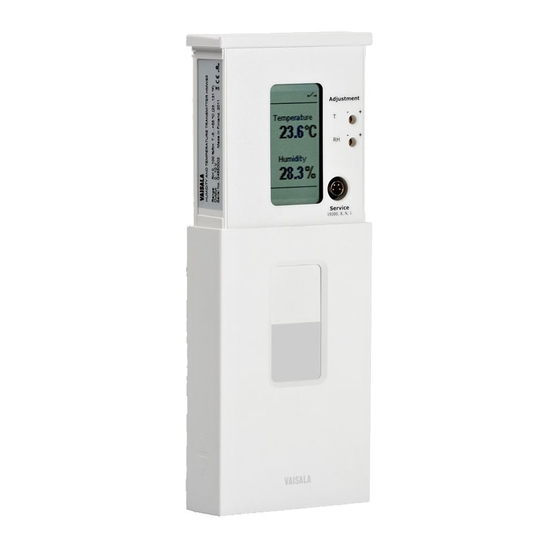
- DIP switches for most common configuration tasks. - RS-485 line for temporary service use with hand-held MI70 indicator or PC. - User exchangeable measurement module available as a spare part. 1111-062 Figure 1 HMW90 Series Transmitters VAISALA ________________________________________________________________________ 13... -
Page 16: Hmw90 Series Transmitters
HMW90 HMW90 series wall-mount transmitter that has been TMW90 customized at Vaisala. Check type label on transmitter body and terminal label on the mounting base. Note for customized transmitters with analog outputs: Keep the transmitter in custom mode (DIP switch 8 set to custom) to retain the custom configuration. -
Page 17: Output Parameters Explained
Sum of the internal energy of a btu/lb thermodynamic system. NOTE Humidity parameters are not measured by TMW92, TMW93, and TMW90 transmitters even though the parameters can be selected using the service port (serial line and MI70 indicator use). VAISALA ________________________________________________________________________ 15... -
Page 18: Transmitter Parts
User's Guide _______________________________________________________________________ Transmitter parts 1201-004 Figure 2 Transmitter Parts - Outside where 1 = Locking screw for mounting base. Not included, M3×6 recommended. 2 = Adjustment trimmers 3 = Service port 4 = Window for display (only in models where the display is visible) 5 = Locking screw for slide. -
Page 19: Figure 3 Opening The Transmitter
Chapter 2 ___________________________________________________________ Product Overview 1201-005 Figure 3 Opening the Transmitter where 1 = Push tab down with a screwdriver to open the transmitter. VAISALA ________________________________________________________________________ 17... -
Page 20: Figure 4 Transmitter Parts - Inside (Analog Output Models)
User's Guide _______________________________________________________________________ 1201-006 Figure 4 Transmitter Parts – Inside (Analog Output Models) where 1 = Mounting base 2 = Opening for cable (wiring from top) 3 = Terminal label 4 = Opening for cable (wiring from behind) 5 = Orientation arrow – should point up after the mounting base has been installed. -
Page 21: Figure 5 Transmitter Parts - Inside (Digital Output Models)
10 = RS-485 termination jumper (connects a 120 Ω resistor). 11 = Rotary switch for relay setpoint (only for models with relay); see section Relay Configuration in DIP Mode on page 23. ® 12 = HTM10 module with HUMICAP sensor. VAISALA ________________________________________________________________________ 19... - Page 22 User's Guide _______________________________________________________________________ This page intentionally left blank. 20 ___________________________________________________________________ M211399EN-F...
-
Page 23: Chapter 3 Installation
These two configuration methods are mutually exclusive. If the DIP switch configuration is used, software settings have no effect on settings that are controlled by the DIP switches. DIP switch number 8 is the master switch that controls which configuration method is used. VAISALA ________________________________________________________________________ 21... -
Page 24: Dip Switches Of Analog Output Models
User's Guide _______________________________________________________________________ DIP Switches of Analog Output Models 1 2 3 4 5 6 7 8 1 2 3 4 5 6 7 8 HMW92/TMW92 HMW93/TMW93 1111-066 Figure 6 DIP Switch Settings of Analog Output Models Position Setting Non-metric Non-metric units (°F). -
Page 25: Relay Configuration In Dip Mode
70 %RH 35 °C (95 °F) 80 %RH 40 °C (104 °F) 90 %RH 45 °C (113 °F) NOTE The rotary switch only has 10 positions. Do not turn the switch so that it is between two positions. VAISALA ________________________________________________________________________ 23... -
Page 26: Figure 7 Relay High In Dip Mode (Hmw93)
User's Guide _______________________________________________________________________ For examples of relay behavior in DIP mode, see Figure 7 and Figure 8 on page 24. Note also the following: - Relay operation in DIP mode is linked to RH measurement on HMW93, and to T measurement on TMW93. - Relay contacts are open if the transmitter is in error state (an active error is present). -
Page 27: Configuration Of Digital Output Models
- Some configuration actions can be done using the BACnet and Modbus protocols. See the following appendices for protocol implementation details: - Appendix A, BACnet Reference, on page 87. - Appendix B, Modbus Reference, on page 103. VAISALA ________________________________________________________________________ 25... -
Page 28: Dip Switches Of Digital Output Models
User's Guide _______________________________________________________________________ DIP Switches of Digital Output Models Parity Even Modbus Non-Metric 128 64 32 16 8 1 2 3 4 5 6 7 8 2 3 4 5 6 7 8 Baud Address Rate Metric (Binary Weighting) BACnet Parity None HMW95 1209-016... -
Page 29: Addressing With Bacnet Protocol
BACnet MS/TP MAC address range is 0 … 255. The transmitter is a BACnet MS/TP master if address is below 128. Otherwise the transmitter is a slave. Addressing with Modbus Protocol Transmitter is always a Modbus slave. MAC Address range for Modbus slaves is 1 … 247. VAISALA ________________________________________________________________________ 27... -
Page 30: Selecting Location
User's Guide _______________________________________________________________________ Selecting Location The conditions at the location should represent well the area of interest. Do not install the transmitter on the ceiling. Avoid placing the transmitter near heat and moisture sources, close to the discharge of the supply air ducts, and in direct sunlight. -
Page 31: Wiring
If you want to use a single power supply for the HMW92, you must connect the positive terminals (+T and +RH) together. Power supply 10 ... 28 VDC = 0 ... 600 Ω 1211-007 Figure 13 Three-Wire Wiring for HMW92 VAISALA ________________________________________________________________________ 29... -
Page 32: Wiring Hmw93
User's Guide _______________________________________________________________________ Wiring HMW93 Recommended wiring for long cables: Relay -RH +RH Power supply 18 ... 35 VDC or 24 VAC ±20% max. 50 VDC = 10 kΩ min. 500 mA 1111-068 Figure 14 Wiring HMW93 3-wire connection with -Vs as common ground. Maximum cable resistance is 2.5 Ω... -
Page 33: Wiring Tmw92
3-wire connection with -Vs as common ground. Maximum cable resistance is 2.5 Ω (24V supply, 0 ... 10 V output, relay not used). Relay Power supply 18 ... 35 VDC or 24 VAC ±20% = 10 kΩ min. 1202-119 Figure 18 Three-Wire Wiring for TMW93 VAISALA ________________________________________________________________________ 31... -
Page 34: Connecting A Common Ac Power Supply To Several Transmitters
User's Guide _______________________________________________________________________ Connecting a Common AC Power Supply to Several Transmitters If you are connecting a common 24 VAC power supply to several transmitters, make sure to connect the same terminal to +Vs and –Vs on all transmitters. This will avoid a short-circuit through the shared common line at the controller;... -
Page 35: Wiring Hmw95
Connect the cable shield to ground on the building controller side. Building controller Transmitter Transmitter Transmitter Power supply RS-485: BACnet or MODBUS master SHIELD Shld Shld Shld Set RS-485 Connect shield on controller side termination jumper 1209-015 Figure 21 Several Transmitters on Same RS-485 Line VAISALA ________________________________________________________________________ 33... - Page 36 User's Guide _______________________________________________________________________ This page intentionally left blank. 34 ___________________________________________________________________ M211399EN-F...
-
Page 37: Chapter 4 Operation
This chapter contains information that is needed to operate the HMW90 series transmitters. Display Startup Screens When the transmitter is powered on, it displays a sequence of information screens. The screens are shown for a few seconds each. 1111-073, 1111-074 Figure 22 HMW93 Startup Screens VAISALA ________________________________________________________________________ 35... -
Page 38: Measurement Screen
User's Guide _______________________________________________________________________ Measurement Screen Measurement screen shows the measured parameters and currently active indicators. 1111-071 Figure 23 HMW93 Measurement Screen – Normal Operation If there is a problem with measurement, affected readings are replaced with stars. The alarm indicator and an error message will also appear on the screen. -
Page 39: Indicators On The Display
Service Port You can connect to the service port on the HMW90 series transmitters using a PC or an MI70 indicator. The MI70 indicator is the hand-held display device that is included with, for example, the Vaisala ® HUMICAP Hand-Held Humidity and Temperature Meter HM70. -
Page 40: Connecting With A Pc
When connecting using a PC, use the Vaisala USB cable (Vaisala order code 219690) and a suitable terminal application: - If you have not used the Vaisala USB cable before, install the driver before attempting to use the cable. Refer to section Installing the Driver for the USB Service Cable on page 38 for detailed instructions. -
Page 41: Terminal Application Settings
Serial line to connect to field. Note: You can check which port the USB cable is using with the Vaisala USB Instrument Finder program that has been installed in the Windows Start menu. Check that the other serial settings are correct for your connection, and change if necessary. -
Page 42: Figure 25 Putty Terminal Application
User's Guide _______________________________________________________________________ 0807-004 Figure 25 PuTTY Terminal Application 40 ___________________________________________________________________ M211399EN-F... -
Page 43: List Of Serial Commands
Show or set calibration information. DSEL Select parameters to display on screen. FRESTORE Restore transmitter to factory settings. RMODE Show or set relay operation mode. RSEL Show or set relay parameter and limits. RTEST [open/closed] Test relay operation. VAISALA ________________________________________________________________________ 41... -
Page 44: Transmitter Information
User's Guide _______________________________________________________________________ Transmitter Information Show Transmitter Information The ? command outputs a listing of device information. ?<cr> Example: >? Device : HMW93 SW version : 1.00.0.0000 SNUM : G5130008 HTM10 module information Software version : 1.00.0 SNUM : G5130007 Show Transmitter Firmware Version Use the VERS command to show the transmitter model and firmware version. -
Page 45: Show Transmitter Status
: 127 (7Fh) Node type : Master Baud setting : Auto Current baudrate : 19200 8N1 Baudrate locked : No Baud detection interval: 10 s : Communication enabled Valid frames Invalid frames Unwanted frames Lost tokens Failed TX VAISALA ________________________________________________________________________ 43... - Page 46 User's Guide _______________________________________________________________________ Example (display full status): >status Device Name : HMW92 Copyright : Copyright Vaisala Oyj 2012 SW Name : XM90 SW Model : XM9x SW version : 1.0.3.3728 Serial number : H1840005 Address SUB FUNCTIONS * Serial Port (COM1) *...
-
Page 47: Show Measured Parameters
Show Command Help To see a short description of an individual command, issue the command with a question mark as a parameter. Example: >calcs ? Display measured quantities VAISALA ________________________________________________________________________ 45... -
Page 48: Show Command List
User's Guide _______________________________________________________________________ Show Command List Use the HELP command to list the currently available serial commands. If the PASS command has not been used, only the basic serial commands are available. HELP<cr> Example (shows basic serial commands, advanced commands are not enabled here): >help CALCS... -
Page 49: Select Units
: 0.00 ... 5.00 (error: 5.50) Example (set channel 1 to 0 ... 1 V output, with error level at 2 V): >amode 1 0 1 2 Aout 1 range ( V) : 0.00 ... 1.00 (error: 2.00) VAISALA ________________________________________________________________________ 47... -
Page 50: Set Analog Output Scaling
User's Guide _______________________________________________________________________ Set Analog Output Scaling Use the ASEL command to select the output parameter and scaling for analog output channels. ASEL [channel parameter lo_value hi_value]<cr> where channel = Analog output channel, 1 or 2. parameter = Parameter that is output on the channel. Available parameters are: relative humidity temperature... -
Page 51: Set Output Clipping And Error Limit
-5 ... 55 °C. Error state is 6 V, which is set when the measured value is 5% outside the scaled output range. Now give the following AOVER command: >aover 2 10.0 20.0 Aout 2 clipping : 10.00 % Aout 2 error limit : 20.00 % VAISALA ________________________________________________________________________ 49... -
Page 52: Display Settings
User's Guide _______________________________________________________________________ Channel 2 now behaves like this: - Clipping is now set to 10%, meaning the output is allowed to vary between 0.6 ... 5.4 V. The channel will output the measurement for -11 ... 61 °C, but range 1 ... 5 V remains scaled to show -5 ... 55 °C. - Error limit is 20%, which means channel 2 will show the error state (6 V) when the measured value is 20% outside the scaled output range. -
Page 53: Serial Line Output Commands
INTV. You can stop the output with the S command. Since the interface is half-duplex, you must enter the commands when the transmitter is not outputting. Stop Measurement Output You can stop the measurement output with the S command: S<cr> VAISALA ________________________________________________________________________ 51... -
Page 54: Output A Reading Once
User's Guide _______________________________________________________________________ Output a Reading Once Use the SEND command to output a single measurement message. SEND<cr> Example: >send RH = 21.72 %RH T = 23.12 'C Set Output Interval Use the INTV command to change the output interval of the automatically repeating measurement messages. -
Page 55: Set Output Format
Tdf =-15.14 'C T = 24.40 'CTdf =-15.14 'C T = 24.40 'CTdf =-15.14 'C T = 24.40 'CTdf =-15.14 'C T = 24.40 'CTdf =- 15.13 'C T = 24.40 'CTdf =-15.13 'C T = 24.40 'C ... VAISALA ________________________________________________________________________ 53... -
Page 56: Serial Line Settings
User's Guide _______________________________________________________________________ Table 9 FORM Command Parameters Measured Parameter Abbreviation in FORM Command Relative humidity Temperature Dew/frost point temperature Dewpoint temperature Wetbulb temperature Enthalpy Mixing ratio Absolute humidity Dew/frost point depression Table 10 FORM Command Modifiers Modifier Description Length modifier (number of digits and decimal places) Tabulator Carriage-return Line feed... -
Page 57: Set Serial Line Response Time
Hi_active (relay closed when above setpoint) Fault (relay closed when transmitter in error state) Not_fault (relay closed when transmitter not in error state) Example (set relay to Lo_active mode): >pass 9000 >rmode lo_active Relay mode : Lo_Active VAISALA ________________________________________________________________________ 55... -
Page 58: Set Relay Parameter And Limits
User's Guide _______________________________________________________________________ Set Relay Parameter and Limits Use the RSEL command to show or set the parameter that controls the relay, and the limits that are applied. RSEL [parameter lo_value hi_value]<cr> where parameter = Parameter that controls the relay. Available parameters are: relative humidity temperature... -
Page 59: Relay Configuration Examples
RSEL RH 60 70 Relay closed RMODE Hi_Active Relay open Time 1111-119 Figure 26 Relay Hi_Active in Custom Mode (HMW93) Relay closed RSEL RH 60 70 RMODE Lo_Active Relay open Time 1111-120 Figure 27 Relay Lo_active in Custom Mode (HMW93) VAISALA ________________________________________________________________________ 57... -
Page 60: Calibration And Adjustment Commands
User's Guide _______________________________________________________________________ Calibration and Adjustment Commands The following sections describe the calibration and adjustment commands of the HMW90 series. For general information on performing calibration and adjustment on the serial line, see section Adjustment Using a PC on page 71. The 1-point humidity adjustment of the HMW90 series adjusts both offset and gain, depending on the adjustment condition. -
Page 61: 1-Point Adjustment Of Rh Measurement
If you have entered user adjustments using the CRH command but do not wish to commit them, use the CRH CANCEL command. CRH [SAVE | CANCEL]<cr> Example (two point adjustment, low point 11 %RH and high point 75 %RH): >pass 9000 >crh lo 11 >crh hi 75 >crh save VAISALA ________________________________________________________________________ 59... -
Page 62: Clear User Adjustment Of Rh Measurement
User's Guide _______________________________________________________________________ Clear User Adjustment of RH Measurement CRH [RESET]<cr> Example: >pass 9000 >crh reset Adjust Temperature Measurement Use the CT command to perform an adjustment of the temperature measurement. You can do a 1-point adjustment or clear the adjustment information from the HTM10 module. -
Page 63: Clear User Adjustment Of T Measurement
To enter a text string with spaces, enclose the string in quotation marks. Use the CDATE to store the date. CTEXT [text]<cr> CDATE [YYYY-MM-DD]<cr> Examples: >pass 9000 >ctext “adjusted rhlab/Tech021” “adjusted rhlab/Tech021” >cdate 2011-12-08 Calibration date : 2011-12-08 VAISALA ________________________________________________________________________ 61... -
Page 64: Testing Commands
User's Guide _______________________________________________________________________ Testing Commands Test Analog Outputs Use the ATEST command to force the analog outputs to the given value. Before using the ATEST command it is useful to give the AMODE command to verify the output mode of the channels. ATEST [channel value]<cr>... -
Page 65: Test Relay Operation
>rtest Relay test mode : Canceled Other Commands Enable Advanced Serial Commands Use the PASS command to enable the advanced serial commands. PASS [passcode]<cr> where passcode = Passcode to enable advanced commands is 9000. Example: >pass 9000 VAISALA ________________________________________________________________________ 63... -
Page 66: Reset Transmitter
User's Guide _______________________________________________________________________ Reset Transmitter Use the RESET command to reset the transmitter. RESET<cr> Example: >reset Resetting HMW93 / 1.00.00.0000 / XM90 > Set BACnet Parameters Use the BACNET command to show or set some of the transmitter’s BACnet parameters. You can also use the BACNET command to reinitialize the BACnet stack of the transmitter without having to reset or power cycle the transmitter. - Page 67 : 127 (007Fh) COV_Interval Autobaud_Interval : 10 Example (change Location to “101”, Description to “main_hall”, and reinitialize the BACnet stack): >bacnet name 101 Name : 101 >bacnet description main_hall Description : main_hall >bacnet reinit Reinitialize signaled to BACnet stack. VAISALA ________________________________________________________________________ 65...
- Page 68 User's Guide _______________________________________________________________________ This page intentionally left blank. 66 ___________________________________________________________________ M211399EN-F...
-
Page 69: Chapter 5 Maintenance
Do not use cleaning agents or solvents, or blow pressurized air into the transmitter housing. ® Do not attempt to clean contaminated HTM10 modules and HUMICAP sensors. Dirty modules should always be replaced with new calibrated modules. VAISALA ________________________________________________________________________ 67... -
Page 70: Calibration And Adjustment
User's Guide _______________________________________________________________________ Calibration and Adjustment HMW90 series transmitters are fully calibrated as shipped from factory. Calibration and adjustment services are available through Vaisala Service Centers. For contact information, see www.vaisala.com/servicecenters HMW90 series transmitters have a display that makes it easy to compare the measured readings against any portable calibration reference. -
Page 71: Adjustment Using Display And Trimmers
Figure 29 Trimmer Centering Screen If you wish to apply a greater correction than allowed by the trimmer in a single adjustment, re-enter the adjustment screen and apply a new correction. Corrections applied using the trimmers are cumulative. VAISALA ________________________________________________________________________ 69... -
Page 72: Adjustment Using An Hm70
Adjustment Using an HM70 Connect the HMW90 series transmitter to the HM70 hand-held meter using the connection cable (Vaisala order code 219980). Depending on the connected devices, you may be prompted by the HM70 meter to check the currently applied environment settings. -
Page 73: Adjustment Using A Pc
Chapter 5 _______________________________________________________________ Maintenance Adjustment Using a PC For more detailed instructions on using the Vaisala USB cable and a terminal application, see section Connecting With a PC on page 38. For a description of the serial commands, see section Calibration and Adjustment Commands on page 58. -
Page 74: Repair Maintenance
User's Guide _______________________________________________________________________ Repair Maintenance Replacing the Measurement Module If you cannot restore the measurement accuracy of the transmitter by calibration and adjustment, you can replace the measurement module inside the transmitter. The measurement module is the small separate component board that is connected to the bottom of the component board;... -
Page 75: Figure 31 Replacing The Htm10 Module (Hmw93)
Verify that there are no errors when the transmitter starts up. If you see the errors HTM10 01 or HTM10 02 on the screen, it is likely that the module is not seated properly in the connector. In that case, disconnect the transmitter body and try again. VAISALA ________________________________________________________________________ 73... - Page 76 User's Guide _______________________________________________________________________ This page intentionally left blank. 74 ___________________________________________________________________ M211399EN-F...
-
Page 77: Chapter 6 Troubleshooting
2. If you are using remote echo on the transmitter, disable it with the ECHO OFF command to avoid collisions. 3. There may be an intermittent connection problem between the transmitter and your terminal. Issue the command again. VAISALA ________________________________________________________________________ 75... -
Page 78: Error Messages
User's Guide _______________________________________________________________________ Error Messages Error Messages on the Display Table 12 Error Messages on the Display Error Message Possible Cause and Solution HTM10 01 Communication failure with HTM10 HTM10 02 module. Reconnect the module and check that it sits firmly in place. -
Page 79: View Error Table
2. Replace the module if unable to remove the problem. Internal problem with the transmitter. 1. Reset the transmitter. 2. Restore the factory settings using service port or DIP switches if reset does not help. VAISALA ________________________________________________________________________ 77... -
Page 80: Error State
User's Guide _______________________________________________________________________ Error State If there are any active “critical” or “error” level errors active in the transmitter, both analog outputs are set into a defined error level instead of the measured result. The error level depends on the output type: - For 0 ... -
Page 81: Reverting To Factory Settings
Figure 33 on page 80. Do not move the switches in the other bank. 1 2 3 4 5 6 7 8 1 2 3 4 5 6 7 8 HMW92/TMW92 HMW93/TMW93 1203-018 Figure 32 DIP Switches in Factory Reset Position VAISALA ________________________________________________________________________ 79... -
Page 82: Reverting To Factory Settings Using Service Port
User's Guide _______________________________________________________________________ Parity Even Modbus Non-Metric 2 3 4 5 6 7 8 Baud Rate Metric BACnet Parity None HMW95 1209-028 Figure 33 DIP Switches in Factory Reset Position (HMW95) Reconnect the transmitter cover to the mounting base so it powers up. -
Page 83: Technical Support
Chapter 6 ____________________________________________________________ Troubleshooting Technical Support For technical questions, contact the Vaisala technical support by e-mail at helpdesk@vaisala.com. Provide at least the following supporting information: - Name and model of the product in question. - Serial number of the product. - Page 84 User's Guide _______________________________________________________________________ This page intentionally left blank. 82 ___________________________________________________________________ M211399EN-F...
-
Page 85: Chapter 7 Technical Data
Digital temperature sensor Table 15 Operating Environment Property Description / Value Operating temperature range -5 ... +55 °C (+23 ... +131 °F) Storage temperature range -30 ... +60 °C (-22 ... +140 °F) Electromagnetic compliance EN61326-1, Industrial Environment VAISALA ________________________________________________________________________ 83... -
Page 86: Table 16 Inputs And Outputs
User's Guide _______________________________________________________________________ Table 16 Inputs and Outputs Property Description / Value HMW92 and TMW92 Outputs HMW92 2 x 4 ... 20 mA, loop powered TMW92 1 x 4 ... 20 mA, loop powered Loop resistance 0 ... 600 Ω Supply voltage 20 ... -
Page 87: Spare Parts And Accessories
HMW90 Temperature Module TM10SP for TMW92, TMW93, and TMW90 Connection cable for HM70 hand-held 219980 meter USB cable for PC connection 219690 Standard white sliding cover, blank DRW237354SP Standard white sliding cover with hole DRW237339SP for display VAISALA ________________________________________________________________________ 85... -
Page 88: Dimensions In Mm
User's Guide _______________________________________________________________________ Dimensions in mm 1111-061 Figure 34 HMW90 Series Dimensions 59.5 29.8 30.5 1111-142 Figure 35 Dimensions of the Mounting Base 86 ___________________________________________________________________ M211399EN-F... -
Page 89: Appendix Abacnet Reference
BACnet Smart Actuator (B-SA) List of all BACnet Interoperability DS-RP-B, DS-RPM-B, DS-WP-B, DS-COVU-A, Building Blocks Supported DM-DDB-B, DM-DOB-B, DM-DCC-B, DM-RD-B (Annex K): See also section BIBBs Supported page 100. Segmentation Capability Segmentation Requests Supported Segmentation Responses Supported VAISALA ________________________________________________________________________ 87... - Page 90 User's Guide _______________________________________________________________________ Standard Object Types Supported Analog Input Analog Output Analog Value Averaging Binary Input Binary Output Binary Value Calendar Command Device Event Enrollment File Group ...
- Page 91 ® ® IBM /Microsoft DoubleByte Character Set (DBCS) ISO 8859-1 ISO 10646 Universal Character Set-2 (UCS2) ISO 10646 (UCS-4) Japanese Industrial Standard (JIS) C 6226 Types of non-BACnet equipment None /network(s) supported: VAISALA ________________________________________________________________________ 89...
-
Page 92: Device Object
Table 19 below describes the properties of the device object. Note the following: - Writable means writable via BACnet - Max_Master and Max_Info_Frames are required in a Master device. - UV = Configured at Vaisala factory to a unique value. See additional information after the table. Table 19 Device Object Properties... -
Page 93: Object_Identifier
Must be unique in BACnet network. As Object Identifier is 22 bits long its value range is 0 ... 4194303. Each device is assigned a random value in this range at Vaisala factory. Object_Name Must be unique in BACnet network. Default object name contains the name and serial number of the device. -
Page 94: Protocol_Services
User's Guide _______________________________________________________________________ Protocol_Services Who-Is, I-Am, Who-Has, I-Have and UnconfirmedCOVNotification services are available only when HMW90 is MS/TP master. Reinitialize Device service must be password protected. According to BACnet protocol, password is character string having max 20 characters. Default password is "1234". Password can be changed through the service port by using the BACNET command. -
Page 95: Status Flags
Other measurement error Event State Table 23 Event State State Cause 0 NORMAL Reliability equals 0 (NO FAULT DETECTED) 1 FAULT Reliability not 0 Out of Service Out of Service value is writable. By Default = FALSE. VAISALA ________________________________________________________________________ 93... -
Page 96: Temperature Object
User's Guide _______________________________________________________________________ Temperature Object Table 24 Temperature Object Properties Property Data type Writable Value or Initial Value Persistence (Application Type) (Conformance Code) Object_Identifier BACnetObjectIdentifier No (R) 00 00 00 03 (hex) Nonvolatile Object Type = 0, Instance = 3 Object_Name CharacterString No (R) -
Page 97: Reliability
Other measurement error Event State Table 27 Event State State Cause 0 NORMAL Reliability equals 0 (NO FAULT DETECTED) 1 FAULT Reliability not 0 Out of Service Out of Service value is writable. By Default = FALSE. VAISALA ________________________________________________________________________ 95... -
Page 98: Calculated Humidity Objects
"Dewpoint depression" 121/120 (ΔºK/ ΔºF) "Tw" "Wet bulb temperature" 62/64 (ºC/ ºF) "a" "Absolute humidity" 217/2000 grams-per-cubic-meter / grains-per-cubic- foot - Vaisala defined unit "x" "Mixing ratio" 28/2001 grams-of-water-per-kilogram-dry-air / grains-of-water-per-pound - Vaisala defined unit "h" "Enthalpy" 149/24 kilojoules-per-kilogram-dry-air / btus-per-... -
Page 99: Status Flags
Event State Table 32 Event State State Cause 0 NORMAL Reliability equals 0 (NO FAULT DETECTED) 1 FAULT Reliability not 0 Out of Service Out of Service value is writeable. By Default = FALSE. Parameter is volatile. VAISALA ________________________________________________________________________ 97... -
Page 100: Operation Pressure Object
User's Guide _______________________________________________________________________ Operation Pressure Object User can set current atmospheric pressure to improve the calculation accuracy of pressure dependent humidity parameters. Table 33 Operation Pressure Object Properties Property Data type Writable Value or Initial Value Object Identifier BACnet Object Identifier 00 80 00 01 (hex) Object Type = 2, Instance = 1... -
Page 101: Operation Altitude Object
Flag State Cause IN_ALARM FALSE Always FALSE FAULT FALSE Always FALSE OVERRIDDEN FALSE Always FALSE OUT_OF_SERVICE FALSE Always FALSE Event State Event State value is always NORMAL. Out of Service Out of Service value is not writeable. VAISALA ________________________________________________________________________ 99... -
Page 102: Bibbs Supported
User's Guide _______________________________________________________________________ BIBBs Supported Table 37 below lists all the BIBBs which, per ANSI/ASHRAE Standard 135-2008, could be supported by a BACnet Smart Sensor (B-ASC). The checked BIBBs are supported by the device. Table 37 BACnet Smart Sensor BIBBs Support Application Service (B-SS) Designation Supported... -
Page 103: Application Services Supported
UnconfirmedEventNotification UnconfirmedPrivateTransfer UnconfirmedTextMessage UTCTimeSynchronization VT-Close VT-Data VT-Open Who-Has Who-Is Who-Is-Router-To-Network WriteProperty WritePropertyMultiple VAISALA _______________________________________________________________________ 101... - Page 104 User's Guide _______________________________________________________________________ This page intentionally left blank. 102 __________________________________________________________________ M211399EN-F...
-
Page 105: Appendix Bmodbus Reference
03 (0x03) Read Holding Registers Class 0 04 (0x04) Read Input Register Class 1 06 (0x06) Write Single Register Class 1 16 (0x10) Write Multiple Registers Class 0 43 / 14 (0x2B / 0x0E) Read Device Identification VAISALA _______________________________________________________________________ 103... -
Page 106: Register Map
User's Guide _______________________________________________________________________ Register Map All data available via the Modbus interface is grouped in five contiguous blocks of registers as described in Table 40 below. Table 40 HMW90 Modbus Register Blocks Metric Non-metric Data Format Description address address 0001…0006 6401…6406 32-bit IEEE float Measurement data... -
Page 107: 16-Bit Integer Format
0019…0020 0266 (×0.01) kJ/kg 6419…0020 6466 (×0.01) btu/lb Available measurements depend on the instrument configuration. Values may be unavailable also in case of device failure. Read status registers or exception status outputs to check for failures. VAISALA _______________________________________________________________________ 105... -
Page 108: Status Registers (Read-Only)
User's Guide _______________________________________________________________________ Status Registers (Read-Only) Table 43 HMW90 Modbus Status Registers Name Address Description Error code (bits 15…0) 0513,6913 0 = no errors Configuration Registers Configuration parameter registers are used to configure the measurement. Writing out-of-range values is silently ignored. NOTE Elevation is linked to pressure according to the following equation: 5.25588... -
Page 109: Device Identification Objects
“Unavailable” value (a quiet NaN for floating point data or 0x0000 for integer data) is returned instead. An exception is generated only for any access outside the register blocks defined in Table 40 on page 104. VAISALA _______________________________________________________________________ 107... - Page 110 *M211399EN*...