
Related Manuals for Vaisala PTU300


Summary of Contents for Vaisala PTU300
- Page 1 USER'S GUIDE Vaisala Combined Pressure, Humidity, and Temperature Transmitter PTU300 M210796EN-F...
- Page 2 The contents are subject to change without prior notice. Please observe that this manual does not create any legally binding obligations for Vaisala towards the customer or end user. All legally binding commitments and agreements are included exclusively in the applicable supply contract or Conditions of...
-
Page 3: Table Of Contents
Trademarks ................16 License Agreement ..............17 Warranty.................. 17 CHAPTER 2 PRODUCT OVERVIEW................19 Introduction to PTU300............19 Basic Features and Options..........20 New and Improved Features Compared to PTU200 ..20 Pressure Measurement............21 Structure of the Transmitter ..........22 Probe Options .............. - Page 4 USER'S GUIDE____________________________________________________________________ Alternate Wiring Systems ............37 Signal and Power Supply Wiring .........38 8-Pin Connector..............39 D-9 Connector ..............40 Connections to a 24 VAC Power Supply......41 Probe Mounting ..............42 General Instructions for Probes with Cable......42 PTU303 for General Use.............44 PTU307 for High Humidities..........45 Temperature Probe (Optional) ..........45 Optional Modules ..............46 Power Supply Module ............46...
- Page 5 PRES and XPRES ............108 PFIX ................109 PSTAB ................. 109 Pressure Average Calculation........... 110 Pressure............... 110 Relative Humidity (RH) and Temperature (T) Filtering ................ 111 FILT................111 Device Information ............112 Using Serial Line ............113 VAISALA ________________________________________________________________________ 3...
- Page 6 USER'S GUIDE____________________________________________________________________ ?..................113 LIGHT ................114 HELP ................114 ERRS................115 VERS................115 Resetting Transmitter using Serial Line ......115 RESET................115 Locking Menu/Keypad using Serial Line ......116 LOCK................116 Serial Output Settings............117 Using Display/Keypad ............117 Using Serial Line ...............118 SERI ................118 SMODE ................119 ADDR ................119 INTV ................120 SDELAY ...............120 ECHO ................120 Data Recording ..............121...
- Page 7 LC................166 MPCI ............... 167 MPC ................ 168 Relative Humidity Adjustment ..........169 Using Push Buttons............169 Using Display/Keypad ............170 Using Serial Line ............... 171 CRH ................171 Relative Humidity Adjustment After Sensor Change ..173 VAISALA ________________________________________________________________________ 5...
- Page 8 USER'S GUIDE____________________________________________________________________ Using Display/Keypad ............173 Using Serial Line ...............173 FCRH................173 Temperature Adjustment .............174 Using Display/Keypad ............174 Using Serial Line ...............175 Analog Output Adjustment (Ch1 and Ch2) ......176 Using Display/Keypad ............176 Using Serial Line ...............176 ACAL ................176 Feeding Adjustment Information ........177 Using Display/Keypad ............177 Using Serial Line ...............177 CTEXT................177...
- Page 9 32-Bit Floating Point Format ........208 16-Bit Integer Format ........... 209 Measurement Data (Read-Only) ........210 Status Registers (Read-Only) ........... 211 Configuration Registers............. 211 Exception Status Outputs ........... 212 Diagnostic Sub-Functions........... 213 Device Identification Objects ..........214 Exception Responses ............214 VAISALA ________________________________________________________________________ 7...
- Page 10 USER'S GUIDE____________________________________________________________________ List of Figures Figure 1 Transmitter Body ..............22 Figure 2 Inside the Transmitter...............23 Figure 3 PTU301 Fixed Probe ..............24 Figure 4 PTU301 Short Cable Probe............24 Figure 5 Probe Options................25 Figure 6 Standard Mounting ..............27 Figure 7 Mounting with Wall Mounting Kit ..........28 Figure 8 Dimensions of the Plastic Mounting Plate (mm/inch) ....28 Figure 9...
- Page 11 Cable Installation with Cable Gland ........199 Figure 91 Probe Installation with Cable Gland ........200 Figure 92 Vapor Tight Installation............201 Figure 93 Wall Mounting Installation ............201 Figure 94 Meteorological Installation Kit for Outdoor Installation... 202 VAISALA ________________________________________________________________________ 9...
- Page 12 Table 4 Basic Quantities Measured by PTU300 ........21 Table 5 Optional Quantities Measured by PTU300.......21 Table 6 Optional Pressure Quantities Measured by PTU300 ....21 Table 7 Wiring of the Optional 8-Pin Connector........39 Table 8 Pin Assignments to RS-232/485 Serial Output ......40 Table 9 Connecting the Twisted Pair Wires to the Screw Terminals ..56...
-
Page 13: General Information
- Chapter 8, Technical data, provides the technical data of the product. - Appendix A, Probe installation kits and installation examples, presents the installation kits available for PTU300 and provides some installation examples. - Appendix B, Calculation Formulas, presents the formulas used for the calculated output quantities. -
Page 14: Version Information
USER'S GUIDE____________________________________________________________________ Version Information Table 1 Manual Revisions Manual Code Description M210796EN-F May 2011. This manual. Applicable from transmitter software version 5.10 onward. Added MODBUS protocol. Updated serial line command descriptions. Updated storage temperature range. M210796EN-E November 2009. Previous version. Added PTU301 short cable probe. -
Page 15: Safety
Chapter 1 ________________________________________________________ General Information Safety The PTU300 delivered to you has been tested for safety and approved as shipped from the factory. Note the following precautions: WARNING Ground the product, and verify outdoor installation grounding periodically to minimize shock hazard. -
Page 16: Recycling
Regulatory Compliances EU Declaration of Conformity The Vaisala Combined Pressure, Humidity, and Temperature Transmitter PTU300 is in conformity with the provisions of the following EU directives: - Low Voltage Directive - EMC-Directive Conformity is shown by compliance with the following standards: - EN 60950-1: Information technology equipment –... -
Page 17: Dnv Type Approval
Chapter 1 ________________________________________________________ General Information DNV Type Approval The Vaisala Combined Pressure, Humidity, and Temperature Transmitter PTU300 is found to comply with Det Norske Veritas' Rules for Classification of Ships, High Speed & Light Craft and Det Norske Veritas' Offshore standards. -
Page 18: Transmitters With Wlan Interface
003 du Canada. Patent Notice The Vaisala HUMICAP® Humidity, and Temperature Transmitter Series PTU300 is protected by, for example, the following patents and their corresponding national rights: Finnish patents 98861 and 99164, French patents 6650303 and 9504397, German patents 69418174 and 19513274, Japanese patents 3585973 and 2801156, UK patents 0665303 and 2288465, and U.S. -
Page 19: License Agreement
Chapter 1 ________________________________________________________ General Information License Agreement All rights to any software are held by Vaisala or third parties. The customer is allowed to use the software only to the extent that is provided by the applicable supply contract or Software License Agreement. - Page 20 USER'S GUIDE____________________________________________________________________ This page intentionally left blank. 18 __________________________________________________________________ M210796EN-F...
-
Page 21: Chapter 2 Product Overview
Alternatively, digital outputs RS-232 (standard) or RS-422/485 (optional) can be selected. A local display is also available. The quantities measured and calculated by PTU300 are presented in Table 4 on page 21. The quantities available as an option are presented in Table 5 on page 21. -
Page 22: Basic Features And Options
USER'S GUIDE____________________________________________________________________ Basic Features and Options - Pressure redundancy option: two sensors in one unit - Two accuracy classes for pressure measurement - Several probes for various applications - A 3 h trend and tendency available in pressure measurement - Calculated output quantities available - Different probe mounting kits, sensor protection options and probe cable lengths - Transmitter mounting kits for multiple installation purposes... -
Page 23: Pressure Measurement
Chapter 2 __________________________________________________________ Product Overview Pressure Measurement The PTU300 series transmitters use a BAROCAP® silicon capacitive absolute sensor developed by Vaisala for barometric pressure measurement applications. The measurement principle of the PTU300 series digital transmitters is based on an advanced RC oscillator and three reference capacitors against which the capacitive pressure sensor and capacitive temperature compensation sensor are continuosly measured. -
Page 24: Structure Of The Transmitter
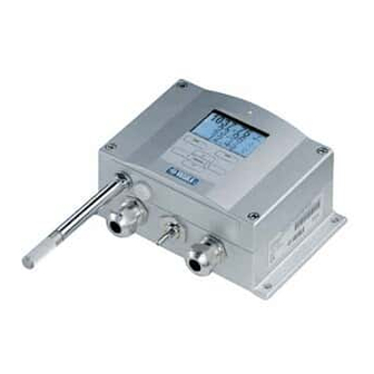
USER'S GUIDE____________________________________________________________________ Structure of the Transmitter 1104-078 Figure 1 Transmitter Body The numbers refer to Figure 1 above: Signal + powering cable gland, or WLAN antenna connector Pressure port Cable gland for optional module Cover screw (4 pcs) Display with keypad (optional) Cover LED 22 __________________________________________________________________ M210796EN-F... -
Page 25: Figure 2 Inside The Transmitter
Relay, RS-422/485, data logger, LAN, WLAN, or analog output module (optional) Grounding connector for power supply module Adjustment buttons (chemical purge buttons) with indicator Output isolation module (optional) Temperature probe cable Humidity probe cable BARO1 module Pressure port Power supply module. VAISALA _______________________________________________________________________ 23... -
Page 26: Probe Options
USER'S GUIDE____________________________________________________________________ Probe Options The PTU301 is intended for wall-mounted applications. The standard version has a fixed probe. 1104-079 Figure 3 PTU301 Fixed Probe The PTU301 short cable probe is a special version for use with the WLAN module, and when LAN module and power supply module are simultaneously installed. -
Page 27: Figure 5 Probe Options
Probe Options The following numbers refer to Figure 5 above: PTU303 Probe for general use PTU307 for demanding processes (optionally warmed and vapor tight probe) Temperature probe Probe cable lengths are 2 m, 5 m, and 10 m. VAISALA _______________________________________________________________________ 25... -
Page 28: Warmed Probe Ptu307
USER'S GUIDE____________________________________________________________________ Warmed Probe PTU307 Temperature difference between the probe and external environment can cause a risk of condensation on the sensor. A wet probe cannot observe the actual humidity in the ambient air. If the condensed water is contaminated, the life span of the probe may shorten and calibration may change. -
Page 29: Chapter 3 Installation
The housing can be mounted either without the mounting plate or with optional mounting plates. Standard Mounting without Mounting Plate Mount the housing by fastening the transmitter to the wall with 4 screws, for example, M6 (not provided). 0601-011 Figure 6 Standard Mounting VAISALA _______________________________________________________________________ 27... -
Page 30: Wall Mounting With Wall Mounting Kit
The following numbers refer to Figure 7 above: Plastic mounting plate Mount the plate to wall with 4 screws M6 (not provided) Arched side up Fasten PTU300 to the mounting plate with 4 fixing screws M3 (provided) Holes for wall/junction box mounting 0804-065... -
Page 31: Figure 9 Dimensions Of The Probe Holder Plate (Mm/Inch)
Chapter 3 _______________________________________________________________ Installation The PTU301 short cable probe is designed to be wall mounted with the probe holder plate (Vaisala order code 226252). The probe holder plate is similar to the standard mounting plate, except for the probe holder at the bottom. -
Page 32: Mounting With Din Rail Installation Kit
Mounting with DIN Rail Installation Kit DIN rail installation kit includes a wall mounting kit, 2 clip-fasteners and 2 screws M4 x 10 DIN 7985 (Vaisala order code 215094). Attach two spring holders to the plastic mounting plate by using the screws provided in the installation kit. -
Page 33: Pole Installation With Installation Kit For Pole Or Pipeline
Pole Installation with Installation Kit for Pole or Pipeline Installation kit for pole or pipeline (Vaisala order code: 215108) includes the metal mounting plate and 4 mounting nuts for pole mounting. When mounting, the arrow in the metal mounting plate must point upward;... -
Page 34: Figure 13 Mounting With Metal Wall Mounting Plate
The following numbers refer to Figure 13 above: Mount the plate to wall with 4 screws M8 (not provided) Fasten the PTU300 to the mounting plate with 4 fixing screws M6 (provided) Note the position of the arrow when mounting. This side must be up when mounting. -
Page 35: Mounting Rain Shield With Installation Kit
(provided) Fasten the mounting plate with rain shield with installation kit to the wall or to the pole (see pole installation) Fasten PTU300 to the mounting plate with 4 fixing screws (provided) Panel Mounting Frame To enable a neat and dirt free embedded installation of the transmitter, a panel mounting frame is available as an option (Vaisala order code: 216038). -
Page 36: Figure 16 Panel Mounting Frame
USER'S GUIDE____________________________________________________________________ 0704-002 Figure 16 Panel Mounting Frame The following numbers refer to Figure 16 above: Panel (not included) Panel mounting frame 0804-083 Figure 17 Panel Mounting Dimensions (mm/inch) 34 __________________________________________________________________ M210796EN-F... -
Page 37: Wiring
When there is high electric noise level (for example, near powerful NOTE electric motor) in the operating environment it is recommended to use shielded cable or take care that the signal cables are separated from other cables. VAISALA _______________________________________________________________________ 35... -
Page 38: Grounding The Cables
USER'S GUIDE____________________________________________________________________ Grounding the Cables Ground the screen of the electrical cable properly to achieve the best possible EMC performance. 0504-049 Figure 19 Grounding the Screen of Electrical Cable 36 __________________________________________________________________ M210796EN-F... -
Page 39: Grounding The Transmitter Housing
If it is needed to have galvanic isolation of the power supply line from the output signals, PTU300 can be ordered with optional output isolation module. This module prevents harmful grounding loops. Alternate Wiring Systems There are three optional ways to connect the transmitter: using basic wiring, using 8-Pin connector, or using D-9 connector. -
Page 40: Signal And Power Supply Wiring
USER'S GUIDE____________________________________________________________________ Signal and Power Supply Wiring When wiring the power supply module, see section Power Supply Module on page 46. 0506-028 Figure 20 Screw Terminal Block on Motherboard The following numbers refer to Figure 20 above: Power supply terminals 10 ... 35 VDC, 24 VAC User port (RS-232 terminals) Analog signal terminals Make sure that you connect only de-energized wires. -
Page 41: 8-Pin Connector
Supply + Supply + Blue Data in RX Ch 3+ Shield/Red Cable shield Cable shield Cable shield NOTE The 8-pin connector cannot be used with relay modules or power supply module that have AC (mains) power connection. VAISALA _______________________________________________________________________ 39... -
Page 42: D-9 Connector
USER'S GUIDE____________________________________________________________________ D-9 Connector 0605-123 Figure 22 Wiring of Optional D-9 Connector Table 8 Pin Assignments to RS-232/485 Serial Output Wire Color Serial Signal RS-232 C RS-485 White Black Yellow Brown Ground Green Blue Ground for supply voltage Ground for supply voltage Grey Orange Supply voltage... -
Page 43: Connections To A 24 Vac Power Supply
To prevent fire and/or damage, if either 24 VAC wire is grounded or connected to a "-", "0", or "GND" terminal of any other device, you must connect the same wire on the "-" terminal also on this instrument. 0703-041 Figure 23 Connections to 24 VAC Power Supply VAISALA _______________________________________________________________________ 41... -
Page 44: Probe Mounting
USER'S GUIDE____________________________________________________________________ Probe Mounting In humidity measurement and especially in calibration it is essential that temperature of the probe and measuring environment is the same. Even a small difference in temperature between the environment and the probe causes an error. As the curve below shows, if the temperature is +20 °C and the relative humidity 100 %RH, a difference of ±1 °C between the environment and the probe causes an error of ±6 %RH. -
Page 45: Figure 25 Horizontal Mounting Of Probe
Vertical Mounting of Probe The following numbers refer to Figure 26 above: To be sealed Insulate the cable To be insulated Let the cable hang loosely. This prevents condensed water running to the sensor along the cable. VAISALA _______________________________________________________________________ 43... -
Page 46: Ptu303 For General Use
If this is not possible and the probe must be inserted from the top, the point of entry must be carefully insulated. For Vaisala probe installation kits and some installation examples see Appendix A on page 195. PTU303 for General Use The PTU303 is a small size (d=12mm) probe for general use, up to +80 °C (+176 °F). -
Page 47: Ptu307 For High Humidities
The PTU307 RH+T probe is suitable for temperatures up to +180°C (+356°F). Note that the operational temperature limit for the PTU307 probe is higher than for the PTU300 transmitter itself. The upper temperature limit for barometric pressure measurement is +60°C (140°F). -
Page 48: Optional Modules
USER'S GUIDE____________________________________________________________________ Optional Modules Power Supply Module The AC (mains) power connection may be connected to the power supply module only by an authorized electrician. A readily accessible disconnect device shall be incorporated in the fixed wiring. 0506-027 Figure 27 Power Supply Module The following numbers refer to Figure 27 above: Connect AC (mains) voltage wires to these terminals... -
Page 49: Installation
Do not detach the power supply module from the transmitter when the WARNING power is on. WARNING Do not connect the mains power to power supply module when it is not installed in the transmitter. Always connect protective ground terminal. WARNING VAISALA _______________________________________________________________________ 47... -
Page 50: Warnings
Ta inte loss strömförsörjningsmodulen från mätaren när strömmen är på. Anslut inte strömförsörjningsmodulen till nätet när den inte är installerad i PTU300-mätaren Anslut alltid en skyddande jordningsplint. Questo prodotto è conforme alla Direttiva sul basso voltaggio (2006/95/CEE). - Page 51 (2006/95/EØS). Netstrømskoblingen til må kun tilsluttes strømforsyningsmodulet af en autoriseret elinstallatør Strømforsyningsmodulet må ikke løsgøres fra senderen, mens spændingen er sluttet til. Slut ikke netspændingen til strømforsyningsmodulet, når det ikke er installeret i PTU300- senderen Forbind altid den beskyttende jordklemme! Dit product voldoet aan de eisen van de richtlijn 2006/95/EEG (Laagspanningsrichtlijn).
- Page 52 Elektros tinklą su energijos tiekimo moduliu sujungti gali tik įgaliotas elektrikas. Niekada neišimkite energijos tiekimo modulio iš siųstuvo, kai maitinimas yra įjungtas. Jei energijos tiekimo modulis nėra įmontuotas PTU300 siųstuve, nejunkite jo į elektros tinklą. Visada prijunkite prie apsauginės įžeminimo jungties! Šis produkts atbilst Zemsprieguma direktīvai (2006/95/EEC).
-
Page 53: Galvanic Isolation For Output
Galvanic Isolation for Output If galvanic isolation of the power supply line from the output signals is needed, PTU300 can be ordered with optional output isolation module. This module prevents harmful grounding loops. Output isolation module is not needed when using the power supply NOTE module. -
Page 54: Installation And Wiring
USER'S GUIDE____________________________________________________________________ Installation and Wiring Disconnect the power. In case the analog output module is installed in the factory, continue with the step 4. To attach the module, open the transmitter cover and fasten the analog output module to the position for MODULE 1 with four screws. -
Page 55: Relays
Chapter 3 _______________________________________________________________ Installation Relays PTU300 can be equipped with one or two configurable relay modules. Each module contains two configurable relays. See the contact ratings in section Technical Specifications of Optional Modules on page 186. Installation and Wiring Disconnect the power and open the transmitter cover. In case the relay-module is installed in the factory, continue with step 5. -
Page 56: Figure 31 Relay Module
USER'S GUIDE____________________________________________________________________ 0503-037 Figure 31 Relay Module The following numbers refer to Figure 31 above: Indication led for the relay 1 or 3 Relay test buttons Flat cable pins Indication led for relay 2 or 4 The relay module may contain dangerous voltages even if the WARNING transmitter power has been disconnected. -
Page 57: Rs-422/485 Interface
When selecting an RS-232 to RS-485 converter for the network, avoid self-powered converters, as they do not necessarily support the needed power consumption. NOTE RS-232 User Port on PTU300 main board cannot be used and connected when RS-485 module is connected. Service port is operating normally. 1102-023 Figure 32... -
Page 58: Installation And Wiring
If you use RS-422 or RS-485 to connect just one PTU300 to a master computer, enable the internal termination of PTU300 by switching switches 1 and 2 ON. Make sure that the master's end of the line is also terminated (by using master's internal termination or with a separate terminator). -
Page 59: Figure 33 4-Wire Rs-485 Bus
Baud > 112K Stub < 1ft, 0.3m 1102-028 Figure 33 4-Wire RS-485 Bus Table 10 4-Wire (Switch 3: On) RS-485 master Data PTU300 → Tx D1+ Rx D1+ → Tx D0- Rx D0- ← Rx D1+ Tx D1+ ← Rx D0- Tx D0- VAISALA _______________________________________________________________________ 57... -
Page 60: Figure 34 2-Wire Rs-485 Bus
Figure 34 2-Wire RS-485 Bus Table 11 2-Wire (Switch 3: Off) RS-485 master Data PTU300 ↔ ↔ When operating in communication mode RS-422, set both switches 3 and 4 to ON position (4-wire wiring is required for RS-422 mode). Connect the power and close the cover. -
Page 61: Lan Interface
RS-232 User Port is disabled. The LAN interface module must be installed at the factory (when ordering the transmitter), or by a Vaisala Service Center. Once installed, the module is automatically used by the transmitter. The physical connection to the network is made to the RJ45 connector on the LAN interface module, using a standard twisted pair Ethernet cable (10/100Base-T). -
Page 62: Wlan Interface
USER'S GUIDE____________________________________________________________________ 0709-003 Figure 35 LAN Interface Module The following numbers refer to Figure 35 above: Flat cable connector RJ45 connector with indicator LEDs for link and activity WLAN Interface The optional WLAN interface enables a wireless Ethernet connection (IEEE 802.11b) to the transmitter. The user can establish a virtual terminal session using a Telnet client program such as PuTTY or by using MODBUS TCP protocol. -
Page 63: Attaching The Wlan Antenna
Attaching the WLAN Antenna The LAN interface module must be installed at the factory (when ordering the transmitter), or by a Vaisala Service Center. Before taking the transmitter into use, you must attach the antenna of the WLAN interface into the RP-SMA connector on the transmitter cover. The location of the antenna is shown in Figure 80 on page 191. -
Page 64: Data Logger Module
USER'S GUIDE____________________________________________________________________ Data Logger Module The optional data logger module extends the data storage for the measurement data. When the data logger is present, this storage is automatically used by the transmitter. The stored data can be browsed using the optional display module, and accessed through the serial connections. -
Page 65: Figure 37 Data Logger Module
The data logger module must be installed at the factory (when ordering the transmitter), or by a Vaisala Service Center. Once installed, the module is automatically used by the transmitter. When the module requires a new battery, the transmitter must be sent to Vaisala for maintenance. VAISALA _______________________________________________________________________ 63... - Page 66 USER'S GUIDE____________________________________________________________________ This page intentionally left blank. 64 __________________________________________________________________ M210796EN-F...
-
Page 67: Chapter 4 Operation
The pressure has an effect on humidity calculations and accuracy. Therefore, accurate calculations can be achieved only when the ambient pressure is taken into consideration. PTU300 uses measured pressure for compensation by default. See section Pressure Compensation Settings on page 107 for instructions on how to set the pressure. -
Page 68: Display/Keypad (Optional)
USER'S GUIDE____________________________________________________________________ Display/Keypad (Optional) The optional display and keypad combination enables shortcuts for viewing current settings and status of the device, current measurement values, and graph of the recent measurement history. Additionally the device has user friendly, visible menu system for adjusting settings and turning functions on or off. -
Page 69: Pressure 3H Trend And Tendency Reading
Figure 40 on page 68. Source: The World Meteorological Organization (WMO) publication Manual on Codes Vol. I.1, International Codes, Part A - Alphanumerical Codes, 1995 Edition, WMO - No. 306. Section C, Code Table 0200: a. VAISALA _______________________________________________________________________ 67... -
Page 70: Figure 40 Pressure Tendency Description
USER'S GUIDE____________________________________________________________________ 0604-055 Figure 40 Pressure Tendency Description The following numbers refer to Figure 40 on page 68: Increasing, then decreasing; atmospheric pressure the same or higher than three hours ago Increasing, then steady; or increasing, then increasing more slowly; atmospheric pressure now higher than three hours ago Increasing (steadily or unsteadily);... -
Page 71: Using Serial Line
Quantities and Units, starting on page 100. Missing Trend The PTU300 series barometers output a code "*" when the pressure tendency has not yet been calculated - that is, less than three hours have elapsed since the power-up of the barometer. The absence of the pressure trend is indicated in a similar manner, too. -
Page 72: Graphic History
USER'S GUIDE____________________________________________________________________ Graphic History The graphical display shows the data trend or min/max graph of the selected quantities, one at a time. The graph is updated automatically while measuring. 0706-052 Figure 41 Graphical Display Trend graph: Shows you a curve of average values. Each value is a calculated average over a period. -
Page 73: Figure 42 Graphical Display With Data Logger
(dashed vertical line) has occurred after the chosen moment. In this case, the exact time difference between the present and the cursor position is not exactly known. If the data logger module is installed, the time is known and the question marks are not present. VAISALA _______________________________________________________________________ 71... -
Page 74: Information Display
USER'S GUIDE____________________________________________________________________ Information Display The information display contains current settings and status of the device. You can open the display by pressing the left function button INFO in the basic display. The following information will be shown: - Current sensor operation (for example, chemical purge), if any, in progress - Present or past unacknowledged errors, if any - Device identification;... -
Page 75: Menus And Navigation
Go back to the basic display by keeping the right-hand button pressed for four seconds. Open the Main Menu by pressing any of the ▼▲◄► buttons. Scroll to the System menu option, and press the ► button. The menu option is indicated with the wrench symbol. VAISALA _______________________________________________________________________ 73... -
Page 76: Rounding Setting
USER'S GUIDE____________________________________________________________________ Scroll to the Language menu option, and the left-hand button. The menu option is indicated with the flag symbol. Select the language with the ▼▲ buttons, and confirm the selection by pressing the left-hand button. Press the right-hand button to exit to the basic display. -
Page 77: Keypad Lock (Keyguard)
Use the display/keypad to restore the factory settings. This operation does not affect the adjustments. Only settings available in the menus are restored. Press any of the arrow buttons to open the Main Menu. Select System, press the right arrow button. VAISALA _______________________________________________________________________ 75... -
Page 78: Display Alarms
USER'S GUIDE____________________________________________________________________ Select Factory settings and press the REVERT key to confirm your selection. Press the YES key to reset all settings to the factory defaults. In case you change your mind and want to exit the menu without making any changes, press the NO key. -
Page 79: Configuring A Display Alarm
Changes you do on the alarm editing page will take effect immediately, and may cause an alarm to appear on the screen. To select a quantity for the alarm, press the CHANGE button and select the quantity from the list. VAISALA _______________________________________________________________________ 77... -
Page 80: Figure 48 Modifying An Alarm Limit
USER'S GUIDE____________________________________________________________________ To modify or remove the alarm limit values, move the selection over the Act. above or Act. below field and press the SET button. You will be prompted to Modify or Remove the value. 0802-070 Figure 48 Modifying an Alarm Limit When modifying the value, use the arrow up and down buttons to change the value under the cursor. -
Page 81: Mi70 Link Program For Data Handling
Start using the program. There is usually no need to select a COM port manually, the MI70 Link software can detect it automatically. The MI70 Link program, and the optional connection cables, are available from Vaisala. See list of accessories in section Options and Accessories on page 189. VAISALA _______________________________________________________________________ 79... -
Page 82: Serial Line Communication
USER'S GUIDE____________________________________________________________________ Serial Line Communication Connect the serial interface by using either the user port or the service port. For permanent interfacing to host system, use the user port. You can change the serial settings and operate in RUN, STOP, SEND, POLL, and MODBUS modes. -
Page 83: User Port Connection
- In SEND mode one measurement message is printed and command prompt is displayed (if echo is on). - In POLL or MODBUS mode, the transmitter does not output anything after power-up. For a description of the modes, see section SMODE on page 119. VAISALA _______________________________________________________________________ 81... -
Page 84: Service Port Connection
PC. Windows will detect the new device, and use the driver automatically. The installation has reserved a COM port for the cable. Verify the port number, and the status of the cable, using the Vaisala USB Instrument Finder program that has been installed in the Windows Start menu. -
Page 85: Using The Service Port
Chapter 4 ________________________________________________________________ Operation There is no reason to uninstall the driver for normal use. However, if you wish to remove the driver files and all Vaisala USB cable devices, you can do so by uninstalling the entry for Vaisala USB Instrument Driver from the Add or Remove Programs (Programs and Features in Windows Vista) in the Windows Control Panel. -
Page 86: Ip Configuration
USER'S GUIDE____________________________________________________________________ IP Configuration The IP settings of the LAN and WLAN interfaces are described in Table 17. The current settings can be viewed on the serial line or using the device information display; see section Information Display on page 72. Table 17 IP Settings for the LAN and WLAN Interfaces Parameter... -
Page 87: Using Display/Keypad
Move the cursor using the ◄► arrow buttons, and change the value under the cursor using the ▲▼ arrow buttons. Confirm the selection by pressing OK. After configuring the desired parameters, press EXIT to apply the changes and return to the basic display. VAISALA _______________________________________________________________________ 85... -
Page 88: Using Serial Line
USER'S GUIDE____________________________________________________________________ Using Serial Line Use the serial line command NET to view or set the network settings for the LAN and WLAN interfaces. You can also refresh the network information or disconnect all active connections. NET [REFRESH] [DISCONNECT] [DHCP WEB] [DHCP IP SUBNET GATEWAY WEB]<cr>... -
Page 89: Wireless Lan Configuration
The security type of the wireless network. The options are: OPEN OPEN/WEP WPA-PSK/TKIP WPA-PSK/CCMP All other choices except OPEN require a security key; see below. Security key The encryption key or passphrase that is used with an encrypted network. VAISALA _______________________________________________________________________ 87... -
Page 90: Using Display/Keypad
USER'S GUIDE____________________________________________________________________ Using Display/Keypad You can configure the Wireless LAN settings using the display/keypad as follows: Press any of the arrow buttons to open the Main Menu. Press the ► arrow button to select Interfaces. Press the ► arrow button to select Network settings. There will be a delay as the transmitter refreshes the network information. -
Page 91: Using Serial Line
Security type of the wireless network. The options are: OPEN OPEN/WEP WPA-PSK/TKIP WPA-PSK/CCMP Examples: >wlan ? Network SSID : WLAN-AP Type : OPEN > >wlan accesspoint wpa-psk/tkip Network SSID : accesspoint Type : WPA-PSK/TKIP WPA-PSK phrase ? thequickbrownfox Save changes (Y/N) ? y > VAISALA _______________________________________________________________________ 89... -
Page 92: Communication Protocol
When accessing the web configuration page, you must first log in. Username: user Password: vaisala The web configuration page provides similar network configuration options as the serial line and the display/keypad. It also has additional options for advanced users. For example, there are more options for securing the wireless network. -
Page 93: Terminal Program Settings
Figure 56 Web Configuration Interface for WLAN Terminal Program Settings The instructions below describe how to connect to the PTU300 using the PuTTY terminal application for Windows. Perform the necessary cabling and configuration of the transmitter before following the instructions. -
Page 94: Opening A Serial/Usb Connection
COM port is selected in the Serial or USB line to connect to field. Change the port if necessary. If you are using a Vaisala USB cable, you can check the port that it uses by clicking the USB Finder... button. This opens the Vaisala USB Instrument Finder program that has been installed along with the USB drivers. -
Page 95: Opening A Telnet Session (Lan/Wlan)
Telnet session. If PuTTY is unable to connect the IP address you entered, it will show you an error message instead. If this happens, check the IP address and the connections, restart PuTTY, and try again. VAISALA _______________________________________________________________________ 93... -
Page 96: List Of Serial Commands
USER'S GUIDE____________________________________________________________________ List of Serial Commands All commands can be issued either in uppercase or lowercase. In the command examples, the keyboard input by the user is in bold type. The notation <cr> refers to pressing the carriage return (Enter) key on your computer keyboard. -
Page 97: Table 21 Data Recording Commands
Select the parameters for the analog outputs ITEST Test the analog outputs AERR Change the analog error output values Table 25 Setting and Testing the Relays Command Description RSEL Set and view the relays RTEST Test the relays VAISALA _______________________________________________________________________ 95... -
Page 98: Table 26 Pressure Commands
USER'S GUIDE____________________________________________________________________ Table 26 Pressure Commands Command Description PRES [hPa] Set the value for pressure compensations XPRES [hPa] Set the value for pressure compensations, temporarily PFIX Select pressure compensation using either a fixed value or using measured value AVRG Set pressure average period HHCP Set height offset for HCP calculation HQNH... -
Page 99: Getting Measurement Message From Serial Line
Outputting Reading Once SEND Use the SEND command to output the reading once in STOP mode. The output format depends on which parameters the transmitter can output. Example: >send 1021.6 hPa T= 23.3 'C RH= 5.7 %RH > VAISALA _______________________________________________________________________ 97... -
Page 100: Assign An Alias For The Send Command
USER'S GUIDE____________________________________________________________________ Assign an Alias for the SEND Command Use the SCOM command to assign a new command that works like the SEND command. The standard SEND command of the transmitter will always function normally whatever the SCOM definition may be. Command names are case-insensitive. -
Page 101: Formatting Serial Line Message
>send RH= 98.4 %RH T= 31.0 'C >ftime on Form. time : ON >send 03:47:59 RH= 98.4 %RH T= 31.0 'C >fdate on Form. date : ON >send 2004-07-05 03:48:03 RH= 98.4 %RH T= 31.0 'C > VAISALA _______________________________________________________________________ 99... -
Page 102: General Settings
USER'S GUIDE____________________________________________________________________ General Settings Changing Quantities and Units Use serial commands or the optional display/keypad to change quantities and units. For more information on available quantities and units, see Table 4 on page 21. For more information on optional quantities, see Table 5 on page 21. -
Page 103: Using Serial Line
Modulus-256 checksum of message sent so far, ascii encoded hexadecimal notation Modulus-65536 checksum of message sent so far, ascii encoded hexadecimal notation NMEA xor-checksum of message sent so far, ascii encoded hexadecimal notation Pressure tendency [* or 0...8] VAISALA ______________________________________________________________________ 101... - Page 104 T= 22.2 'C RH= 38.3 %RH The default output format includes the average value of the measured pressure (quantity P). If your PTU300 is equipped with two pressure transducers, you can add the individual pressure readings from the transducers to the output format (quantities P1 and P2): >form 6.1 "P1="...
-
Page 105: Unit
This command changes both the serial output and display units to either metric or non-metric units. When you want to output both metric and non-metric units simultaneously on the display, select the display units later by using the display/keypad. VAISALA ______________________________________________________________________ 103... -
Page 106: Date And Time
USER'S GUIDE____________________________________________________________________ Date and Time Using Display/Keypad If the optional Data Logger Module is installed, you can change the time and date using the display/keypad. Press any of the arrow buttons to open the Main Menu. Select System and press the ► arrow button to confirm your selection. -
Page 107: Nmea Data Format
Chapter 4 ________________________________________________________________ Operation NMEA Data Format The PTU300 transmitter can be used in connection with a GPS receiver. It responds to a GPS input command by outputting a single predefined NMEA format message or the transmitter serial number. The pressure unit has to be set as bar when the NMEA data output NOTE format is used. -
Page 108: Gps Commands
USER'S GUIDE____________________________________________________________________ Output format: >send $PASHS,XDR,P,0.99710,B,S1630001,C,22.47,C.S1630001,H,20.84, P,S1660001 > Example: "$PASHS,XDR,P," 1.5_P_",B,,C,"_3.2_T_",C,,H,"_RH_",P,"_#r_#n_ Output format: >send $PASHS,XDR,P,1.01148,B,,C, 27.11,C,,H, 54.29,P, > GPS Commands The PTU300 transmitter responds to following GPS specific application commands. *0100P9<cr> Example: >*0100P9 $PASHS,XDR,P,1.03384,B,A2100012,C,22.28,C,A2100012,H,39.65, P,A2100012 > *0200P9<cr> Example: >*0200P9 $PASHS,XDR,P,1.01496,B,T5030004,C,24.42,C,T5030004,H,41.18, P,T5030004 >... -
Page 109: Pressure Compensation Settings
O at 4 °C. Pressure compensation is intended to be used in normal air only. When NOTE measuring in other gases, please contact Vaisala for further information. Using Display/Keypad Use display/keypad to set the pressure compensation. To select the pressure unit using display/keypad see section Changing Quantities and Units on page 100. -
Page 110: Using Serial Line
USER'S GUIDE____________________________________________________________________ Using Serial Line PRES and XPRES Command XPRES must be used if the value is changed frequently (for example, by an automatic system that updates the value). Its value is not retained at reset, and when set to 0, last value set with PRES is used instead. -
Page 111: Pfix
Example of setting the limit to 0.5 hPa: >pdmax Max P diff. : 1.00 ? 0.5 Pdmax limit works as follows: >form 4.1 p1 " " p2 " " p " " u3 " " ERR #r#n VAISALA ______________________________________________________________________ 109... -
Page 112: Pressure Average Calculation
USER'S GUIDE____________________________________________________________________ Example: Maximum pressure difference is within the limit >send 1034.2 1034.4 1034.3 hPa 0000 > Example: Maximum pressure difference exceeds the limit >send 1034.2 1035.4 ****** hPa 1000 > Use the ERRS command to analyze problems. Pressure Average Calculation Pressure The averaging data filter calculates an average pressure over a certain period of time. -
Page 113: Relative Humidity (Rh) And Temperature (T) Filtering
Select Off/Standard/Extended and press the SELECT key. Press the EXIT key to return to the basic display. FILT Use the serial line command FILT [xxx] to set the filtering level. FILT [xxx]<cr> where xxx = OFF, ON, or EXT (default = OFF) VAISALA ______________________________________________________________________ 111... -
Page 114: Device Information
USER'S GUIDE____________________________________________________________________ Device Information The device information contains current configuration; status and settings of the device. The information is available through the display/menu, as well. For more information, see Information Display on page 72. When requesting the device information, the following information will be shown: - Current sensor operation (for example, chemical purge), if any, in progress... -
Page 115: Using Serial Line
Use the serial line command ? to check the current transmitter configuration. Command ?? is similar but can also be used if the transmitter is in POLL mode. Example: >? PTU300 / 3.01 Serial number : A2150004 Batch number : A1450004 Adjust. -
Page 116: Light
USER'S GUIDE____________________________________________________________________ LIGHT Use the LIGHT command to view or set the backlight mode of the display (optional). Issuing the command without specifying a mode shows the current backlight mode. LIGHT [mode]<cr> where mode = Operating mode of the display backlight. The options are: ON (backlight always on) OFF (backlight always off) AUTO (backlight automatically turns on and off when... -
Page 117: Errs
Humidity sensor open circuit. > VERS Use the VERS command to display software version information. Example: >vers PTU300 / 5.10 > Resetting Transmitter using Serial Line RESET Resets the device. The user port switches to start-up output mode selected with command SMODE. -
Page 118: Locking Menu/Keypad Using Serial Line
USER'S GUIDE____________________________________________________________________ Locking Menu/Keypad using Serial Line LOCK Use the LOCK command to prevent the user from entering the menu using the keypad, or to lock the keypad completely. You can optionally set a 4-digit PIN code, for example 4444. If a PIN code has been set, the user will be prompted to enter the code when trying to access the menu. -
Page 119: Serial Output Settings
- In MODBUS mode, only MODBUS protocol communication is available. See Chapter 5, MODBUS, on page 147. Select the RUN interval and the unit. Press OK to confirm. VAISALA ______________________________________________________________________ 117... -
Page 120: Using Serial Line
USER'S GUIDE____________________________________________________________________ Select the Device address and press SET to confirm. Select ECHO, and press ON to turn to it on, OFF to turn it off. Press EXIT to return to the basic display. The new user port settings set using the display/keypad are effective immediately. -
Page 121: Smode
Addresses are required for POLL mode and MODBUS mode (serial MODBUS). ADDR [aa]<cr> where aa = Device address of the transmitter, range 0 ... 255 (default = 0) Example (changing the transmitter address from 0 to 52): >addr Address : 0 ? 52 > VAISALA ______________________________________________________________________ 119... -
Page 122: Intv
USER'S GUIDE____________________________________________________________________ INTV Use the INTV command to set the RUN mode output interval. The time interval is used only when the RUN mode is active. INTV [xxx yyy]<cr> where = Delay, range 1 – 255. = Unit: S, MIN or H. Example (setting the output interval to 10 minutes): >intv 10 min Output interval: 10 min... -
Page 123: Data Recording
Table 4 on page 21. For more information on optional quantities, see Table 5 on page 21. Example: >dsel rh t tdf RH T Tdf > Enter the command without parameters and press ENTER to display the current recording parameters. VAISALA ______________________________________________________________________ 121... -
Page 124: View Recorded Data
USER'S GUIDE____________________________________________________________________ View Recorded Data If the device is provided with the optional display, the graphical display shows the data of the selected quantities, one at a time. For details about graphical display, see section Graphic History on page 70. You may also dump the logged data to the serial line in numeric form with the following commands. - Page 125 (10 s intervals) 2008-04-11 23:41:11 (90 s intervals) 2008-04-11 20:41:11 (12 min intervals) 2008-04-10 21:03:41 10 T (2 h intervals) 2008-03-31 18:03:41 11 T (12 h intervals) 2008-02-04 12:03:41 12 T (3 d intervals) 2007-03-04 00:03:41 > VAISALA ______________________________________________________________________ 123...
-
Page 126: Play
USER'S GUIDE____________________________________________________________________ PLAY Use the PLAY command to output the selected file to the serial line. If the data logger module is installed, you can specify an interval to be outputted. Data in the output is <TAB> delimited. This is compatible with most spreadsheet programs. -
Page 127: Deleting The Recorded Files
Figure 2 on page 23 (DIP switches for analog output settings.) Select the current/voltage output, switch ON either of the switches, 1 or 2. Select the range, switch ON one of the switches from 3 to 7. VAISALA ______________________________________________________________________ 125... -
Page 128: Figure 59 Current/Voltage Switches Of Output Modules
USER'S GUIDE____________________________________________________________________ 0503-045 Figure 59 Current/Voltage Switches of Output Modules The following numbers refer to Figure 59 above: Current/voltage selection output switches (from 1 to 2) Current/voltage range selection switches (from 3 to 7) in analog output 1 and 2 Switches for service use only. -
Page 129: Analog Output Quantities
SELECT key to confirm your selection. Select Scale, lower limit, by pressing the up/down arrow buttons. Press the SET key. Adjust the lower limit value by pressing the arrow buttons up/down/left/right. Press the OK key to confirm your setting. VAISALA ______________________________________________________________________ 127... -
Page 130: Amode/Asel
USER'S GUIDE____________________________________________________________________ Select Scale, upper limit by pressing the up/down arrow buttons. Press the SET key. Adjust the upper limit value by pressing the arrow buttons up/down/left/right. Press the OK key to confirm your setting. Press the EXIT key to return to the basic display. AMODE/ASEL Use the serial line to select and scale the analog output quantities. -
Page 131: Analog Output Tests
= Current or voltage value to be set for channel 3 (optional) (mA or V) Example: >itest 20 5 Ch1 (Td ) 20.000 mA H'672A Ch2 (T 5.000 mA H'34F9 >itest Ch1 (Td ) -23.204 'C 16.238 mA H'FFFE Ch2 (T 22.889 'C 8.573 mA H'5950 > VAISALA ______________________________________________________________________ 129... -
Page 132: Analog Output Fault Indication Setting
USER'S GUIDE____________________________________________________________________ Analog Output Fault Indication Setting Factory default state for analog outputs during error condition is 0 V/ 0 mA. Please be careful when selecting the new error value. The error state of the transmitter should not cause unexpected problems in process monitoring. -
Page 133: Operation Of Relays
"below" value, the relay is passive when the measured value is not between the setpoints. You can also set only one setpoint. See Figure 60 on page 132 for illustrative examples of the different measurement-based relay output modes. VAISALA ______________________________________________________________________ 131... -
Page 134: Figure 60 Relay Output Modes
USER'S GUIDE____________________________________________________________________ 1102-007 Figure 60 Relay Output Modes Mode 4 is usually used if an alarm needs to be triggered when the measured value exceeds a safe range. The relay is active when measurement is in range, and is released if the value goes out of range or the measurement fails. -
Page 135: Hysteresis
Live measurement (data available): relay active (C and NO outputs are closed) No live data (for example: error state, chemical purge or adjustment mode): relay released (C and NC outputs are closed) See Figure 61 on page 134 for illustrative examples of the FAULT/ONLINE STATUSrelay output modes. VAISALA ______________________________________________________________________ 133... -
Page 136: Figure 61 Fault/Online Status Relay Output Modes
USER'S GUIDE____________________________________________________________________ 1102-040 Figure 61 FAULT/ONLINE STATUS Relay Output Modes FAULT/ONLINE STATUS relays are usually used in conjunction with an analog output to obtain validity information for the output value. NOTE If transmitter loses its power, all status-based relays are released similarly to the case of an instrument failure. -
Page 137: Enabling/Disabling Relays
When you have two relay modules, the relays of the module connected to slot MODULE 1 are called “relay 1” and “relay 2” and relays connected to slot MODULE 2 are called “relay 3” and “relay 4”. VAISALA ______________________________________________________________________ 135... -
Page 138: Figure 62 Relay Indicators On Display
USER'S GUIDE____________________________________________________________________ 0706-055 Figure 62 Relay Indicators on Display Number refers to Figure 62 above: Lists enabled relays. Activation state shown in black. Disabled relays are not shown. Use the display/keypad to set the relay outputs. Press any of the arrow buttons to open the Main Menu. Select Interfaces and press the right arrow button. -
Page 139: Rsel
40.00 'C ? - Rel2 T hyst : 2.00 'C ? 2 Rel2 T enabl: ON ? on Rel3 Td above: 5.00 'C ? 10 Rel3 Td below: 0.00 'C ? - Rel3 Td hyst : 1.00 'C ? 1 VAISALA ______________________________________________________________________ 137... -
Page 140: Testing Operation Of Relays
USER'S GUIDE____________________________________________________________________ Rel3 Td enabl: OFF ? on Rel4 Td above: 0.00 'C ? 20 Rel4 Td below: 0.00 'C ? - Rel4 Td hyst : 0.00 'C ? 2 Rel4 Td enabl: OFF ? on > Example of using relay 1 as fault alarm: selecting relay 1 to follow the fault status and relay 2 to follow the temperature measurement. -
Page 141: Rtest
The purge function starts with heating stage, continues with settling and when the temperature of the sensor is decreased the transmitter returns to normal mode. The whole cycle takes about 6 minutes. Chemical purge function locks the output values for about 6 minutes. NOTE VAISALA ______________________________________________________________________ 139... -
Page 142: Automatic Chemical Purge (Interval Purge)
Automatic Chemical Purge (Interval Purge) When PTU300 leaves the factory the automatic chemical purge (if chosen) takes place repeatedly with the time intervals set in the factory. User can change the interval in which the purge takes place by using serial commands or with the optional display/keypad. -
Page 143: Chemical Purge In Power Up
Set the automatic and manual chemical purge by using the display/keypad. Open the Main Menu by pressing any of the arrow buttons. Select Measuring, press the right arrow button Select Chemical purge, press the right arrow button 1102-016 Figure 65 Chemical Purge Settings VAISALA ______________________________________________________________________ 141... -
Page 144: Using Serial Line
USER'S GUIDE____________________________________________________________________ - Start the chemical purge manually by selecting Start purge now and pressing START. - Select Purge on power-up by using the arrow buttons. Press On/Off to turn the start-up purge on/off. - Select Automatic purge and turn it on or off by pressing the ON/OFF key. - Page 145 Do not change the settings for duration, settling, temperature or temperature difference unless instructed by Vaisala personnel. Type PUR and press ENTER to proceed. Skip unchanged values by pressing ENTER. Input changed values in the format shown by the current value (for example, date and time).
-
Page 146: Setting Sensor Heating
Setting Humidity Sensor Heating using Display/Keypad When the PTU300 leaves the factory the sensor heating follows the factory default values. You can enable/disable the function, change the RH-limit and define the heating temperature and duration of this function. -
Page 147: Using Serial Line
0...255 s (default: 30 s) Example: >xheat Extra heat : OFF Extra heat RH : 95 ? 90 Extra heat temp: 100 ? 85 Extra heat time: 30 ? 10 >xheat on Extra heat : ON > VAISALA ______________________________________________________________________ 145... - Page 148 USER'S GUIDE____________________________________________________________________ This page intentionally left blank. 146 _________________________________________________________________ M210796EN-F...
-
Page 149: Chapter 5 Modbus
The PTU300 transmitter can be accessed using the MODBUS serial communication protocol. Support for MODBUS protocol is available on all PTU300 transmitters as a standard feature from software version 5.10 onward. The supported MODBUS variants and the connections they use are listed in Table 34 below. -
Page 150: Taking Modbus Into Use
USER'S GUIDE____________________________________________________________________ Taking MODBUS into Use To take the MODBUS protocol into use on the PTU300, you must perform some configuration tasks using the built-in display and keypad (optional) or a PC connected to the serial line. For example, you can connect to the service port using the USB service cable (Vaisala order code: 219685). -
Page 151: Enabling Serial Modbus
Connect the USB service cable between a computer and the service port of the transmitter. Start the Vaisala USB Instrument Finder program (which has been installed on the computer along with the USB service cable driver), and check the COM port that the cable is using. - Page 152 NOTE The number of data bits must always be 8 for MODBUS RTU. Serial MODBUS interface of the PTU300 does not work with baud rates 115, 150, and 300 b/s. Use the ADDR command to set the MODBUS address of the transmitter.
-
Page 153: Enabling Ethernet Modbus
Press the EXIT button to save the changes. Note that the device address setting is not relevant for MODBUS TCP. In the MODBUS mode, the transmitter will respond to all valid MODBUS messages with any “unit identifier” value. VAISALA ______________________________________________________________________ 151... -
Page 154: Using Serial Line
Connect the USB service cable between a computer and the service port of the transmitter. Start the Vaisala USB Instrument Finder program (which has been installed on the computer along with the USB service cable driver), and check the COM port that the cable is using. - Page 155 For a description of the available settings, see section Wireless LAN Configuration on page 87. The MODBUS configuration is now complete. Reset or power cycle the transmitter to enable the MODBUS mode, and proceed with the installation of the transmitter. VAISALA ______________________________________________________________________ 153...
-
Page 156: Diagnostic Modbus Counters
USER'S GUIDE____________________________________________________________________ Diagnostic MODBUS Counters PTU300 has diagnostic counters that can be used to pinpoint MODBUS problems. The counters are always active when the MODBUS protocol is enabled. Viewing Counters using Display/Keypad You can use the display/keypad option to view and clear the counters. -
Page 157: Disabling Modbus
Alternatively, you can enter the Main Menu using the display/keypad option, and change the mode from the Interfaces submenu. The other communication settings of the output interface (User Port, LAN interface, or WLAN interface) will remain as configured, but the MODBUS protocol will be disabled. VAISALA ______________________________________________________________________ 155... - Page 158 USER'S GUIDE____________________________________________________________________ This page intentionally left blank. 156 _________________________________________________________________ M210796EN-F...
-
Page 159: Chapter 6 Maintenance
Install a new filter on the probe. When using the stainless steel filter, take care to tighten the filter properly (recommended force 5 Nm). New filters can be ordered from Vaisala, see section Options and Accessories on page 189. VAISALA ______________________________________________________________________ 157... -
Page 160: Changing The Sensor
When replacing the sensor, the new sensor must be of the same type as the old sensor (for example, HUMICAP180L2). The sensor type can only be changed at a Vaisala Service Center. To replace the HUMICAP180 or HUMICAP180L sensor: Remove the filter from the probe. See the instructions in section Changing the Probe Filter on page 157. -
Page 161: Error States
Press the INFO button to display the error message. You can also check the error message via the serial interface by using the command ERRS. In case of constant error, please contact Vaisala, see section Technical Support on page 161. VAISALA ______________________________________________________________________ 159... -
Page 162: Table 35 Error Messages
Check that assumed pressure is within measurement range for the transmitter. E28 … E29 Unknown/incompatible module Ensure that the module is compatible with installed in add-on module slot 1 the PTU300. (or 2) Internal analog voltage out of Internal transmitter failure. Remove the range transmitter and return the faulty unit to Vaisala Service. -
Page 163: Technical Support
Chapter 6 ______________________________________________________________ Maintenance Technical Support For technical questions, contact the Vaisala technical support by e-mail at helpdesk@vaisala.com. Provide at least the following supporting information: - Name and model of the product in question - Serial number of the product... - Page 164 USER'S GUIDE____________________________________________________________________ This page intentionally left blank. 162 _________________________________________________________________ M210796EN-F...
-
Page 165: Calibration And Adjustment
Chapter 7 ___________________________________________________ Calibration and adjustment CHAPTER 7 CALIBRATION AND ADJUSTMENT The PTU300 is fully calibrated and adjusted as shipped from factory. Typical calibration interval is two years. Depending on the application it may be good to make more frequent checks. Calibration must be done always when there is a reason to believe that the device is not within the accuracy specifications. -
Page 166: Opening And Closing The Adjustment Mode
USER'S GUIDE____________________________________________________________________ Table 36 Adjustment and Calibration Commands Function Command Linear corrections on/off LCI ON/OFF Entering linear corrections Multipoint corrections on/off MPCI ON/OFF Entering multipoint corrections MPCI Calibration date CDATE Opening and Closing the Adjustment Mode Open the transmitter cover. The buttons needed in adjustment are on the left-hand side of the motherboard. -
Page 167: Pressure Adjustment
Let the readings stabilize. Press the READY key when stabilized. Enter the actual pressure of the reference used using the up/down arrow buttons. Press the OK key. Press the YES key to perform the adjustment. Press the OK to return to the adjustment menu. VAISALA ______________________________________________________________________ 165... -
Page 168: One-Point Adjustment Using Serial Line
USER'S GUIDE____________________________________________________________________ One-Point Adjustment using Serial Line NOTE Making adjustments is possible only after adjustments are unlocked. To unlock the adjustment menu, press the ADJ button on the motherboard of the transmitter. Use the LCI command - to activate or deactivate the linear adjustment function - to enter new linear offset and offset/gain pressure corrections to the transmitter - to edit existing linear offset and offset/gain pressure corrections. -
Page 169: Mpci
: 0.000 ? 1100 P1 5.correction: 0.000 ? 0.32 P1 6.reading : 0.000 ? 1150 P1 6.correction: 0.000 ? 0.33 P1 7.reading : 0.000 ? 1200 P1 7.correction: 0.000 ? 0.34 P1 8.reading : 0.000 ? P1 8.correction: 0.000 ? VAISALA ______________________________________________________________________ 167... -
Page 170: Mpc
USER'S GUIDE____________________________________________________________________ Use the MPC command to view current status of the multipoint corrections. Example: >mpc P1 multi adj. : ON P1 1.reading : 900.000 P1 1.correction: 0.200 P1 2.reading : 950.000 P1 2.correction: 0.220 P1 3.reading : 1000.000 P1 3.correction: 0.270 P1 4.reading : 1050.000 P1 4.correction: 0.310... -
Page 171: Relative Humidity Adjustment
LED is lit continuously). Adjustment cannot be done if the conditions are not stabilized (indicator LED is flashing). Press the NaCl~75% button to adjust the 75 %RH condition. After adjustment transmitter returns to normal operation mode (indicator LED is unlit). VAISALA ______________________________________________________________________ 169... -
Page 172: Using Display/Keypad
USER'S GUIDE____________________________________________________________________ Using Display/Keypad Note that the difference between the two humidity references must be at least 50 %RH. Carry out the chemical purge (if available). Press the ADJ button (opens the ADJUSTMENT MENU). Select Adjust RH measurement, press the right arrow button. Select 1-point/ 2-point adjustment. -
Page 173: Using Serial Line
Note that the difference between the two humidity references must be at least 50 %RH. Connect the PTU300 to a PC. See section Serial Line Communication on page 80. Open a terminal program. Carry out the chemical purge (if available). - Page 174 USER'S GUIDE____________________________________________________________________ When stabilized, type the high end reference value after the question mark and press ENTER. >crh 11.25 Ref1 ? c 11.24 Ref1 ? c 11.24 Ref1 ? 11.3 Press any key when ready ... 75.45 Ref2 ? c 75.57 Ref2 ? c 75.55...
-
Page 175: Relative Humidity Adjustment After Sensor Change
After sensor change, carry out the procedure as described in previous sections. Just replace the CRH command with the FCRH command. FCRH Example: >fcrh 1.82 1. ref Press any key when ready... 74.22 2. ref ? 75 > indicates that the calibration has succeeded. VAISALA ______________________________________________________________________ 173... -
Page 176: Temperature Adjustment
USER'S GUIDE____________________________________________________________________ Temperature Adjustment Using Display/Keypad Press the ADJ button on the motherboard to open the ADJUSTMENT MENU. If using a warmed probe for measuring, probe heating will be interrupted when ADJ button is pressed. Wait some time for the probe to reach ambient temperature. Select Adjust T measurement (or TA measurement for additional probe) press the right arrow button. -
Page 177: Using Serial Line
(date and text) to the transmitter's memory; see the serial commands CTEXT and CDATE. Press the ADJ button on the motherboard to close the adjustment mode. Take the probe out of the reference conditions and replace the filter. VAISALA ______________________________________________________________________ 175... -
Page 178: Analog Output Adjustment (Ch1 And Ch2)
- Current output: 2 mA and 18 mA - Voltage output: 10 % and 90 % of the range Connect PTU300 to a calibrated current/voltage meter in order to measure either current or voltage depending on the selected output type. -
Page 179: Feeding Adjustment Information
Adjust. info : (not set) ? HMK15 > CDATE Use the CDATE command to enter date to adjustment information field. Set the adjustment date in format YYYY-MM-DD. Example: >cdate Adjust. date : (not set) ? 2006-01-22 > VAISALA ______________________________________________________________________ 177... - Page 180 USER'S GUIDE____________________________________________________________________ This page intentionally left blank. 178 _________________________________________________________________ M210796EN-F...
-
Page 181: Chapter 8 Technical Data
Defined as the root sum of the squares (RSS) of endpoint non-linearity, hysteresis error, repeatability error and calibration uncertainty at room temperature. **** Defined as ±2 standard deviation limits of temperature dependence over the operating temperature range. VAISALA ______________________________________________________________________ 179... -
Page 182: Relative Humidity
USER'S GUIDE____________________________________________________________________ Relative Humidity Measurement range 0...100 %RH Accuracy (including non-linearity, hysteresis and repeatability) with HUMICAP®180 for typical applications HUMICAP®180C for applications with chemical purge and/or warmed probe at +15... 25 °C ± 1 %RH (0...90 %RH) ± 1.7 %RH (90...100 %RH) at -20...+40 °C ±... -
Page 183: Temperature (+ Operating Pressure Ranges)
-70...+ 180 ºC (-94...+356 ºF) Typical accuracy: 0.1 ºC (0.18 ºF) Sensor: Pt100 PRT DIN IEC 751 class 1/4 B Cable length: 2 m, 5 m, and 10 m Pressure tight: up to 7 bar Probe material: stainless steel VAISALA ______________________________________________________________________ 181... -
Page 184: Calculated Variables
USER'S GUIDE____________________________________________________________________ Calculated Variables Table 38 Calculated Variables (Typical Ranges) Variable PTU 301 PTU303 PTU 307 Dewpoint -20...+60 ºC -20...+80 ºC -20...+100 ºC temperature Mixing ratio 0...160 g/kg dry air 0...500 g/kg dry air 0...500 g/kg dry air Absolute 0...160 g/m 0...500 g/m 0...500 g/m humidity... -
Page 185: Accuracy Of Mixing Ratio G/Kg (Ambient Pressure 1013 Mbar)
13.4 13.8 14.2 14.6 15.0 15.3 15.7 22.6 23.3 23.9 24.6 25.2 25.8 26.5 27.1 27.8 28.4 39.1 40.0 41.0 42.0 43.0 44.0 45.0 45.9 46.9 47.9 63.5 64.9 66.4 67.8 69.2 70.7 72.1 73.5 74.9 76.4 VAISALA ______________________________________________________________________ 183... -
Page 186: Dewpoint Temperature (Ptu307 Warmed Probe Option)
USER'S GUIDE____________________________________________________________________ Dewpoint Temperature (PTU307 Warmed Probe Option) Find the intersection of the dewpoint temperature curve and the dewpoint difference reading (process temperature-dewpoint temperature) on the x- axis and read the accuracy in dewpoint measurement on the y-axis. Dewpoint temperature (°C) Dewpoint difference (°C) 0508-017 Figure 78... -
Page 187: Inputs And Outputs
LAN (optional) WLAN (optional) Protocols ASCII commands MODBUS RTU MODBUS TCP Relay outputs (optional) 0.5 A, 250 VAC, SPDT Display (optional) LCD with backlight, graphic trend display Menu languages Chinese, English, Finnish, French, German, Japanese, Russian, Spanish, Swedish VAISALA ______________________________________________________________________ 185... -
Page 188: Mechanics
USER'S GUIDE____________________________________________________________________ Mechanics Cable bushing M20x1.5 For cable diameter 8 ... 11mm/0.31 ... 0.43" Conduit fitting 1/2”NPT User cable connector (optional) M12 series 8- pin (male) option 1 with plug (female) with 5 m / 16.4 ft black cable option 2 with plug (female) with screw terminals Probe cable diameter... -
Page 189: Analog Output Module
Operating speed max 115.2 kbaud Bus isolation 300VDC Power consumption at 24V max 50 mA External loads standard loads 32 RL> 10kohm Storage temperature range -55 ... +80 ºC (-67 ... +176 ºF) Max wire size 1.5 mm2 (AWG16) VAISALA ______________________________________________________________________ 187... -
Page 190: Lan Interface Module
USER'S GUIDE____________________________________________________________________ LAN Interface Module Operating temperature range -40 ... +60 ºC (-40 ... +140 ºF) Storage temperature range -40 ... +85 ºC (-40 ... +185 ºF) Operating humidity range 5 … 95 %RH Power consumption at 24V max 60 mA Ethernet type 10BASE-T 100BASE-TX Connector... -
Page 191: Options And Accessories
HMI41 Connection Cable with RJ45 Connector 25917ZZ OUTPUT CABLES FOR 8-PIN CONNECTOR Connection Cable 5m 8-pin M12 Female, Black 212142 Female Connector 8-pin M12 with Screw Terminals 212416 Male Connector 8-pin M12 with Cable and Adapter 214806SP VAISALA ______________________________________________________________________ 189... -
Page 192: Dimensions (Mm/Inch)
USER'S GUIDE____________________________________________________________________ Description Order Code CABLE BUSHINGS Cable Gland M20x1.5 for 8...11mm Cable 214728SP Conduit Fitting M20x1.5 for NPT1/2 Conduit 214780SP Dummy Plug M20x1.5 214672SP WINDOWS SOFTWARE PC Software and cable 215005 OTHER HMK15 Calibration Adapter for 12 mm Probes with 211302SP >7 mm Sensor Pins HMK15 Calibration Adapter for 12 mm Probes with... -
Page 193: Figure 80 Wlan Antenna Dimensions
Chapter 8 ____________________________________________________________ Technical data 0804-033 Figure 80 WLAN Antenna Dimensions VAISALA ______________________________________________________________________ 191... -
Page 194: Ptu301
USER'S GUIDE____________________________________________________________________ PTU301 12 (0.47) 0508-030 Figure 81 PTU301 Fixed Probe Dimensions 0911-064 Figure 82 PTU301 Short Cable Probe Dimensions 192 _________________________________________________________________ M210796EN-F... -
Page 195: Ptu303
Chapter 8 ____________________________________________________________ Technical data PTU303 0804-060 Figure 83 PTU303 Probe Dimensions PTU307 0804-061 Figure 84 PTU307 Probe Dimensions Temperature Probe 0804-062 Figure 85 Optional Temperature Probe Dimensions VAISALA ______________________________________________________________________ 193... - Page 196 USER'S GUIDE____________________________________________________________________ This page intentionally left blank. 194 _________________________________________________________________ M210796EN-F...
-
Page 197: Probe Installation Kits And Installation Examples
Duct installation kit includes a flange, a sealing ring, a supporting bar and probe attaching part for the probe and screws for attaching the flange to the duct wall. Vaisala order codes: 210697 (for PTU303 and PTU307), and 215003 for temperature probe. -
Page 198: Duct Installation Kit For Temperature Probe (For Ptu307)
This prevents errors caused by the heat conduction in the bar and cable. Duct Installation Kit for Temperature Probe (for PTU307) Vaisala duct installation kit for the T-probe includes flange, supporting bar, probe attaching part, sealing ring and the fixing screws (4 pcs). Vaisala order code: 215003. 0507-019... -
Page 199: Pressure Tight Swagelok Installation Kits (For Ptu307)
Pressure Tight Swagelok Installation Kits (For PTU307) RH Probe Installation Swagelok installation kit for the relative humidity probe includes Swagelok connector with ISO3/8" or NPT1/2" thread. Vaisala order codes: SWG12ISO38 or SWG12NPT12. 0508-032 Figure 88 Swagelok Installation Kit for RH-probe... -
Page 200: Temperature Probe Installation
USER'S GUIDE____________________________________________________________________ Temperature Probe Installation Swagelok installation kit for T-probe includes Swagelok connector with either ISO1/8" or NPT1/8" thread. Vaisala order codes: SWG6ISO18 or SWG6NPT18. 135 mm 33 mm 18 mm min P = max 10 bar max 30 mm T = max 180 ºC... -
Page 201: Examples Of Vapor Tight Installations With Cable Gland
Appendix A _________________________________ Probe installation kits and installation examples Examples of Vapor Tight Installations with Cable Gland RH-Probe Installations (for PTU303/307) Cable gland AGRO is available from Vaisala (order code: HMP247CG.) 0508-026 Figure 90 Cable Installation with Cable Gland The following numbers refer to Figure 90 above... -
Page 202: Figure 91 Probe Installation With Cable Gland
0508-018 Figure 91 Probe Installation with Cable Gland Probe installation with a cable gland is not available from Vaisala. The following numbers refer to Figure 91 above 1 = AGRO 1160.20.145 (T= -40 ... +100 ºC) Not available from Vaisala. -
Page 203: T- Probe Installations (Ptu307)
T- Probe Installations (PTU307) 0508-015 Figure 92 Vapor Tight Installation Vapor Tight Installation is not available from Vaisala. The following numbers refer to Figure 92 above: Cable gland. For example AGRO 1100.12.91.065 (T= -25 ... +200 ºC) In pressurized processes, use a locking ring (example: 6x 0.7 DIN471) -
Page 204: Meteorological Installation Kit (For Ptu307)
USER'S GUIDE____________________________________________________________________ Meteorological Installation Kit (for PTU307) The Vaisala meteorological Installation Kit HMT330MIK with a static pressure head enables the PTU307 to be installed outdoors to obtain reliable measurements for meteorological purposes. For more information, see HMT330MIK brochure and order form. -
Page 205: Appendix Bcalculation Formulas
CALCULATION FORMULAS This Appendix contains the formulas used for the calculated output quantities. The PTU300 series transmitters measure relative humidity and temperature. From these values dewpoint, mixing ratio, absolute humidity and enthalpy in normal pressure are calculated using the following equations: Dewpoint: ... - Page 206 USER'S GUIDE____________________________________________________________________ Mixing ratio: Absolute humidity: Enthalpy: . 1 ( 00189 The water vapor saturation pressure P is calculated by using two equations (5 and 6): ...
- Page 207 (K) enthalpy (kJ/kg) Height compensated pressure values (QFE, QNH, and HCP) are calculated using the following equations: where: measured air pressure height difference between the barometer and the reference level (m) 9.81 (m/s 287 (J/kg/K) temperature (K) VAISALA ______________________________________________________________________ 205...
- Page 208 USER'S GUIDE____________________________________________________________________ (10) where: station elevation (m) 9.81 (m/s 287 (J/kg/K) 288.15 (K) α -0.0065 (K/m) (11) where: measured air pressure height difference between the barometer and the reference level (m) 206 _________________________________________________________________ M210796EN-F...
-
Page 209: Appendix Cmodbus Reference
MODBUS REFERENCE This appendix describes the MODBUS functions and data of the transmitter. Function Codes PTU300 supports all MODBUS conformance class 0 and class 1 function codes defined in Open MODBUS/TCP Specification, Release 1.0. Table 40 Supported Function Codes Function Code... -
Page 210: Register Map
TCP Specification, Release 1.0. This is also known as “little-endian” or “Modicon” word order. NOTE Despite the specification, some MODBUS masters may expect “big-endian” word order (most-significant word first). In such case, you must select “word-swapped” floating point format in your MODBUS master for PTU300 MODBUS registers. 208 _________________________________________________________________ M210796EN-F... -
Page 211: 16-Bit Integer Format
In addition to this, 2’s complement makes negative values look like large positive values, which must be taken into account when utilizing the 16-bit register values. VAISALA ______________________________________________________________________ 209... -
Page 212: Measurement Data (Read-Only)
USER'S GUIDE____________________________________________________________________ When writing 16-bit values in configuration registers, they are always processed as signed integers in the range of -32768…+32767. You shall use the floating point registers to write values outside this 16-bit signed integer range. Maximum writable value is 32767 also for configuration registers that do not accept negative values. -
Page 213: Status Registers (Read-Only)
Error information can retrieved also with function code 08, sub-function NOTE Basic status information of the PTU300 transmitter is also available with the Read Exception Status function code 07. For details, see section Exception Status Outputs on page 212. -
Page 214: Exception Status Outputs
MODBUS interface. The service cable must be used to change other configuration settings if needed. Exception Status Outputs Exception status outputs (read with function code 07) tell the summary of the PTU300 transmitter status as described in Table 46 below. Table 46 PTU300 Exception Status Outputs Output... -
Page 215: Diagnostic Sub-Functions
Appendix C ______________________________________________________ MODBUS Reference Diagnostic Sub-Functions PTU300 supports some of the MODBUS diagnostic functions described in the MODBUS Application Protocol Specification V1.1b. These diagnostic functions are accessed with function code 08. See Table 47 below for details. Table 47... -
Page 216: Device Identification Objects
USER'S GUIDE____________________________________________________________________ Device Identification Objects PTU300 MODBUS conforms to the extended identification level defined in the MODBUS Application Protocol Specification V1.1b. Both stream access and individual access to the objects is supported. Table 48 PTU300 MODBUS Device Identification Object Id... - Page 218 *M210796EN*...