Vaisala HUMICAP HMT330 SERIES User Manual
Humidity and temperature transmitter
Hide thumbs
Also See for HUMICAP HMT330 SERIES:
- User manual (161 pages) ,
- Manual (3 pages) ,
- Quick reference manual (40 pages)

Related Manuals for Vaisala HUMICAP HMT330 SERIES


Summary of Contents for Vaisala HUMICAP HMT330 SERIES
- Page 1 USER'S GUIDE Vaisala HUMICAP® Humidity and Temperature Transmitter Series HMT330 M210566EN-J...
- Page 2 The contents are subject to change without prior notice. Please observe that this manual does not create any legally binding obligations for Vaisala towards the customer or end user. All legally binding commitments and agreements are included exclusively in the applicable supply contract or Conditions of...
-
Page 3: Table Of Contents
Grounding the Transmitter Housing........36 Signal and Power Supply Wiring......... 37 Connections to a 24 VAC Power Supply ......38 Probe Mounting ..............40 General Instructions for Probes with a Cable ..... 41 HMT333 for Ducts and Tight Spaces........43 VAISALA ________________________________________________________________________ 1... - Page 4 User's Guide ______________________________________________________________________ HMT334 for High Pressure and Vacuum Applications..43 HMT335 for High Temperatures..........45 HMT337 for High Humidity Applications......46 Temperature Probe (Optional) ........46 HMT338 for Pressurized Pipelines........46 Tightening the Clasp Nut..........48 Optional Modules ..............49 Power Supply Module ............49 Installation ..............50 Warnings ................51 Galvanic Isolation for Output ..........54 Third Analog Output ............54...
- Page 5 SERI................112 SMODE ................ 113 ADDR ................113 INTV ................114 SDELAY ............... 114 ECHO................115 Data Recording..............115 Selecting Data Recording Quantities ........ 115 DSEL................115 View Recorded Data ............116 DIR ................116 PLAY ................117 VAISALA ________________________________________________________________________ 3...
- Page 6 User's Guide ______________________________________________________________________ Deleting the Recorded Files ..........118 UNDELETE ..............119 Analog Output Settings ............119 Changing Output Mode and Range........119 Analog Output Quantities ..........121 AMODE/ASEL ..............122 Analog Output Tests............123 ITEST ................123 Analog Output Fault Indication Setting......124 AERR................124 Operation of Relays..............125 Quantity for Relay Output..........125 Measurement-Based Relay Output Modes .......125 Relay Setpoints ............125 Hysteresis..............127...
- Page 7 Accuracy of Mixing Ratio g/kg (Ambient Pressure 1013 mbar)..............167 Accuracy of Wet Bulb Temperature °C......168 Accuracy of Absolute Humidity g/m³ ......168 Dewpoint Temperature (HMT337 Warmed Probe Option)169 Operating Environment ............. 169 Inputs and Outputs............170 Mechanics ................. 170 VAISALA ________________________________________________________________________ 5...
- Page 8 User's Guide ______________________________________________________________________ Transmitter Weight ............171 Technical Specifications of Optional Modules....171 Power Supply Module ..........171 Analog Output Module..........171 Relay Module ...............172 RS-485 Module ............172 LAN Interface Module...........172 WLAN Interface Module ..........172 Data Logger Module.............173 Options and Accessories ............173 Dimensions (mm/inch) ............175 HMT331................177 HMT333................178 HMT334................178...
-
Page 9: Vaisala
Display Alarms ................. 77 Figure 50 Modifying an Alarm Limit ............77 Figure 51 Service Port Connector and User Port Terminal on Motherboard ................ 79 Figure 52 Connection Example between PC Serial Port and User Port .................. 80 VAISALA ________________________________________________________________________ 7... - Page 10 Figure 98 Vapor Tight Installation............185 Figure 99 Wall Mounting Installation............185 Figure 100 Climate Chamber Installation (not Available from Vaisala) ..186 Figure 101 Example of Installation through Roof ........187 Figure 102 Installing the HMT338 Probe Through a Ball Valve Assembly ................188 Figure 103 Meteorological Installation Kit for Outdoor Installation ...190...
- Page 11 Configuration Parameter Registers........199 Table 41 Configuration Flag Registers..........200 Table 42 HMT330 Exception Status Outputs........200 Table 43 HMT330 MODBUS Diagnostics ..........201 Table 44 HMT330 MODBUS Device Identification ....... 202 Table 45 HMT330 MODBUS Exception Responses......202 VAISALA ________________________________________________________________________ 9...
- Page 12 User's Guide ______________________________________________________________________ This page intentionally left blank. 10 __________________________________________________________________ M210566EN-J...
-
Page 13: General Information
This chapter provides general notes for the manual and the product. About This Manual This manual provides information for installing, operating, and maintaining Vaisala HUMICAP® Humidity and Temperature Transmitter Series HMT330. Contents of This Manual This manual consists of the following chapters: - Chapter 1, General Information, provides general notes for the manual and the product. -
Page 14: Version Information
User's Guide ______________________________________________________________________ - Appendix B, Calculation Formulas, presents the equations used in HMT330 to calculate values of dewpoint, mixing ratio, absolute humidity and enthalpy in normal pressure. - Appendix C, MODBUS Reference, describes the MODBUS functions and data of the transmitter. Version Information Table 1 Manual Revisions... -
Page 15: Safety
Chapter 1 ________________________________________________________ General Information Safety The Vaisala HUMICAP® Humidity and Temperature Transmitter Series HMT330 delivered to you has been tested for safety and approved as shipped from the factory. Note the following precautions: Ground the product, and verify outdoor installation grounding WARNING periodically to minimize shock hazard. -
Page 16: Recycling
Dispose of batteries and the unit according to statutory regulations. Do not dispose of with regular household refuse. Regulatory Compliances EU Declaration of Conformity The Vaisala Vaisala HUMICAP® Humidity and Temperature Transmitter Series HMT330 is in conformity with the provisions of the following EU directives: - Low Voltage Directive (2006/95/EC) -
Page 17: Dnv Type Approval
Chapter 1 ________________________________________________________ General Information DNV Type Approval The Vaisala HUMICAP® Humidity and Temperature Transmitter Series HMT330 is found to comply with Det Norske Veritas' Rules for Classification of Ships, High Speed & Light Craft and Det Norske Veritas' Offshore standards. -
Page 18: Transmitters With Wlan Interface
Cet appareil numérique de la classe [B] est conforme à la norme NMB-003 du Canada. Patent Notice The Vaisala HUMICAP® Humidity and Temperature Transmitter Series HMT330 is protected by, for example, the following patents and their corresponding national rights: Finnish patents 98861 and 99164, French patents 6650303 and 9504397, German patents 69418174 and 19513274, Japanese patents 3585973 and 2801156, UK patents 0665303 and 2288465, and U.S. -
Page 19: License Agreement
Chapter 1 ________________________________________________________ General Information License Agreement All rights to any software are held by Vaisala or third parties. The customer is allowed to use the software only to the extent that is provided by the applicable supply contract or Software License Agreement. - Page 20 User's Guide ______________________________________________________________________ This page intentionally left blank. 18 __________________________________________________________________ M210566EN-J...
-
Page 21: Chapter 2 Product Overview
Chapter 2 __________________________________________________________ Product Overview CHAPTER 2 PRODUCT OVERVIEW This chapter introduces the features, advantages, and the product nomenclature of the Vaisala HUMICAP® Humidity and Temperature Transmitter Series HMT330. Introduction to HMT330 The HMT330 transmitter provides reliable humidity measurement in a wide range of applications. -
Page 22: Basic Features And Options
User's Guide ______________________________________________________________________ Basic Features and Options - Several probes for various applications - User-friendly display - Calculated output quantities available - Different probe mounting kits, sensor protection options and probe cable lengths - Transmitter mounting kits for multiple installation purposes - Chemical purge for applications where interfering chemicals in the measuring environment pose a risk - Warmed probe and sensor heating for high humidity conditions... -
Page 23: Structure Of The Transmitter
The following numbers refer to Figure 1 above: Signal + powering cable gland Cable gland for optional module, or WLAN antenna connector Cable gland for optional module Cover screw (4 pcs) Display with keypad (optional) Cover LED VAISALA _______________________________________________________________________ 21... -
Page 24: Figure 2 Inside The Transmitter
User's Guide ______________________________________________________________________ 0508-010 Figure 2 Inside the Transmitter The following numbers refer to Figure 2 above: Service port (RS-232) DIP switches for analog output settings Power supply and signal wiring screw terminals Relay, data logger, RS-422/485, LAN, or WLAN module (optional) Grounding connector Power supply module (optional) -
Page 25: Probe Options
WLAN module and when LAN module and power supply module are simultaneously installed. It has the HMT333 probe on a short cable (21 cm), and a mounting plate with a probe holder. 1102-024 Figure 4 HMT331 Short Cable Probe VAISALA _______________________________________________________________________ 23... -
Page 26: Figure 5 Probe Options
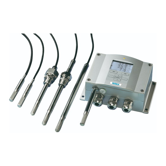
User's Guide ______________________________________________________________________ 0911-066 Figure 5 Probe Options The following numbers refer to Figure 5: HMT333 for ducts and tight spaces HMT334 for high pressure and vacuum applications (up to 100 bars) HMT335 for high temperatures (up to 180 ºC, vapor tight) *) Flange available as an option HMT337 for high humidity applications (optional warmed and vapor tight probe) -
Page 27: Warmed Probe Hmt337
The warmed probe is heated continuously so that its temperature is always higher than in environment. This prevents condensation on the probe. The power consumption of the warmed probe is slightly higher than other probes. VAISALA _______________________________________________________________________ 25... - Page 28 User's Guide ______________________________________________________________________ This page intentionally left blank. 26 __________________________________________________________________ M210566EN-J...
-
Page 29: Chapter 3 Installation
The housing can be mounted either without the mounting plate or with optional mounting plates. Standard Mounting without Mounting Plate Mount the housing by attaching the transmitter to a wall with 4 screws, for example, M6 (not provided). 0804-066 Figure 6 Standard Mounting VAISALA _______________________________________________________________________ 27... -
Page 30: Wall Mounting With Wall Mounting Kit
User's Guide ______________________________________________________________________ Wall Mounting with Wall Mounting Kit When mounting with wall mounting kit the mounting plate (Vaisala order code 214829) can be installed directly on wall or onto a standard wall box (also US junction box). When wiring through back wall, remove the plastic plug from the wiring hole in the transmitter before mounting. -
Page 31: Figure 9 Dimensions Of The Probe Holder Plate (Mm/Inch)
Chapter 3 _______________________________________________________________ Installation The HMT331 short cable probe is designed to be wall mounted with the probe holder plate (Vaisala order code 226252). The probe holder plate is similar to the standard mounting plate, except for the probe holder at the bottom. -
Page 32: Mounting With Din Rail Installation Kit
Mounting with DIN Rail Installation Kit DIN rail installation kit includes a wall mounting kit, 2 clip-fasteners and 2 screws M4 × 10 DIN 7985 (Vaisala order code: 215094). Attach two spring holders to the plastic mounting plate by using the screws provided in the installation kit. -
Page 33: Figure 12 Horizontal Pole
Mount the plate to wall with 4 screws M8 (not provided) Attach the HMT330 to the mounting plate with 4 fixing screws M6 (provided) Note the position of the arrow when mounting. This side must be up when mounting. VAISALA _______________________________________________________________________ 31... -
Page 34: Mounting Rain Shield With Installation Kit
Mounting the Rain Shield with the Installation Kit The following numbers refer to Figure 15 above: = Assemble the rain shield with the installation kit (Vaisala order code: 215109) to the metal mounting plate with 2 (M6) mounting screws (provided) -
Page 35: Panel Mounting Frame
Panel Mounting Frame To enable a neat and dirt free embedded installation of the transmitter, a panel mounting frame is available as an option (Vaisala order code: 216038). The frame is a thin, flexible plastic frame for the transmitter, with adhesive tape on one side. -
Page 36: Wiring
User's Guide ______________________________________________________________________ 0804-083 Figure 17 Panel Mounting Dimensions (mm/inch) Wiring Cable Bushings A single electrical cable with screen and three to ten wires is recommended for power and analog/serial connections. The cable diameter should be 8 ... 11 mm. The number of cable bushings depends on the transmitter options. -
Page 37: Grounding The Cables
Grounding the Cables Ground the screen of the electrical cable properly to achieve the best possible EMC performance. 0504-049 Figure 19 Grounding the Screen of Electrical Cable VAISALA _______________________________________________________________________ 35... -
Page 38: Grounding The Transmitter Housing
User's Guide ______________________________________________________________________ Refer to Figure 19 on page 35 when performing the procedure below. Cut back outer sheath to desired length. Cut back screen braiding or screen foil to dimension X. Push the domed cap nut (item 1) and the seal insert with contact socket of the gland (item 2+3) onto the cable as shown in the diagram. -
Page 39: Signal And Power Supply Wiring
When wiring the optional modules, see the corresponding section for instructions: - RS-422/485 Interface on page 57 - Relays on page 56 - Third Analog Output on page 54 - LAN Interface on page 62 - WLAN Interface on page 63 VAISALA _______________________________________________________________________ 37... -
Page 40: Connections To A 24 Vac Power Supply
User's Guide ______________________________________________________________________ Connect the power supply wires to the connectors: POWER 10 ... 35V+ 24V~ (+) and (-) terminals. If you are using 24 VAC power supply, see the note below before connecting the supply wires. Turn on the power. The indicator LED on the cover lit continuously during normal operation. -
Page 41: Figure 21 Connections To 24 Vac Power Supply
Chapter 3 _______________________________________________________________ Installation 0703-041 Figure 21 Connections to 24 VAC Power Supply VAISALA _______________________________________________________________________ 39... -
Page 42: Probe Mounting
User's Guide ______________________________________________________________________ Probe Mounting In humidity measurement and especially in calibration it is essential that temperature of the probe and measuring environment is the same. Even a small difference in temperature between the environment and the probe causes an error. As the curve below shows, if the temperature is +20 °C and the relative humidity 100 %RH, a difference of ±1 °C between the environment and the probe causes an error of ±6 %RH. -
Page 43: General Instructions For Probes With A Cable
The following numbers refer to Figure 23 above: 1 = To be sealed 2 = To be insulated 3 = Insulate the cable 4 = Let the cable hang loosely. This prevents condensed water running to the probe along the cable. VAISALA _______________________________________________________________________ 41... -
Page 44: Figure 24 Vertical Mounting Of Probe
If this is not possible and the probe must be inserted from the top, the point of entry must be carefully insulated. For Vaisala probe installation kits and some installation examples, see Appendix A on page 181. 42 __________________________________________________________________ M210566EN-J... -
Page 45: Hmt333 For Ducts And Tight Spaces
HMT333 for Ducts and Tight Spaces The HMT333 is a small size (ø = 12mm) general-purpose probe suitable for ducts and channels with the installation kit available from Vaisala. The HMT333 provides for two measuring range options. The first probe version is equipped with a flexible cable and can be used when measuring in environments up to 80 ºC. -
Page 46: Figure 25 Hmt344 Probe
User's Guide ______________________________________________________________________ 0506-029 Figure 25 HMT344 Probe The following numbers refer to Figure 25 above: Tightening cone Fitting screw, M22x1.5 or NPT 1/2" Sealing washer Probe; Ø12 mm Tighten the nut a further 30º (1/12) turn or if you have a torque wrench tighten it with a torque of 80 ±... -
Page 47: Hmt335 For High Temperatures
Refer to Appendix A on page 181 for more information on the duct installation kit for HMT335. To avoid incorrect humidity readings, the temperature differences between inside and outside of the duct must not be remarkable. VAISALA _______________________________________________________________________ 45... -
Page 48: Hmt337 For High Humidity Applications
HMT337 with installation examples: - Duct mounting kit - Cable gland - Pressure tight Swagelok connector - Vaisala's Meteorological Installation kit The installation kits are available for both humidity and temperature probe. Temperature Probe (Optional) An additional temperature probe is available to measure the ambient temperature when the HMT337 (with probe warming) is used. -
Page 49: Figure 28 Hmt338 Probe
- Fitting Body ISO1/2 solid structure - Fitting Body NPT1/2 solid structure Table 5 HMT338 Probe Dimensions Probe type Probe Dimension Adjustment Range Standard 178 mm 120 mm Optional 400 mm 340 mm 0507-025 Figure 29 Sealing of Fitting Body into Process VAISALA _______________________________________________________________________ 47... -
Page 50: Tightening The Clasp Nut
User's Guide ______________________________________________________________________ Tightening the Clasp Nut Adjust the probe to a suitable depth according to the type of installation. Tighten the clasp nut first manually. Mark the fitting screw and the clasp nut. Tighten the nut a further 50 -60º (ca. 1/6 turn) with a wrench. If you have suitable torque wrench, tighten the nut to max 45 ±... -
Page 51: Optional Modules
The following numbers refer to Figure 31 above: Connect AC (mains) voltage wires to these terminals Grounding terminal In case the module is not installed in the factory: Connect wires from these terminals to the POWER 10 ... 35V 24V terminals of the motherboard. VAISALA _______________________________________________________________________ 49... -
Page 52: Installation
User's Guide ______________________________________________________________________ Installation Disconnect the power and open the transmitter cover. Remove the protective plug from the cable gland and thread the wires. In case the power supply module is installed in the factory, continue with the step 5. Attach the power module to the bottom of the housing with four screws. -
Page 53: Warnings
La conduttura elettrica può essere collegata al modulo di alimentazione elettrica soltanto da un elettricista autorizzato. Non staccare l’alimentazione elettrica dal trasmettitore quando è acceso. Non collegare la corrente elettrica al modulo di alimentazione elettrica se non è installato nel trasmettitore HMT330. Collegare sempre il morsetto protettivo a terra! VAISALA _______________________________________________________________________ 51... - Page 54 User's Guide ______________________________________________________________________ Dette produkt er i overensstemmelse med direktivet om lavspænding (2006/95/EØS). Netstrømskoblingen til må kun tilsluttes strømforsyningsmodulet af en autoriseret elinstallatør Strømforsyningsmodulet må ikke løsgøres fra senderen, mens spændingen er sluttet til. Slut ikke netspændingen til strømforsyningsmodulet, når det ikke er installeret i HMT330- senderen Forbind altid den beskyttende jordklemme! Dit product voldoet aan de eisen van de richtlijn 2006/95/EEG...
- Page 55 EEC). Připojení síťového napájení k napájecímu modulu smí provádět pouze oprávněný elektrikář. Neodpojujte napájecí modul od snímače při zapnutém napájení. Nepřipojujte síťové napájení k napájecímu modulu, pokud není instalován ve snímači HMT330. Vždy zapojte ochrannou zemnící svorku! VAISALA _______________________________________________________________________ 53...
-
Page 56: Galvanic Isolation For Output
User's Guide ______________________________________________________________________ Galvanic Isolation for Output If galvanic isolation of the power supply line from the output signals is needed, HMT330 can be ordered with optional output isolation module. This module prevents harmful grounding loops. Output isolation module is not needed when using the power supply NOTE module. -
Page 57: Installation And Wiring
Select the quantity and scale the channel via the serial line or display/keypad, see section Analog Output Quantities on page 121. For testing the analog output, see section Analog Output Tests on page 123. For fault indication setting, see section Analog Output Fault Indication Setting on page 124. VAISALA _______________________________________________________________________ 55... -
Page 58: Relays
User's Guide ______________________________________________________________________ Relays HMT330 can be equipped with one or two configurable relay modules. Each module contains two configurable relays. See the contact ratings in section Technical Specifications of Optional Modules on page 171. Installation and Wiring Disconnect the power and open the transmitter cover. In case the relay-module is installed in the factory, continue with step 5. -
Page 59: Rs-422/485 Interface
115 200 bits/s. (For maximum bus length of 1 km, use bit rate 19200 b/s or less.) When selecting an RS-232 to RS-485 converter for the network, avoid self-powered converters, as they do not necessarily support the needed power consumption. VAISALA _______________________________________________________________________ 57... -
Page 60: Installation And Wiring
User's Guide ______________________________________________________________________ NOTE RS-232 User Port on HMT330 main board cannot be used and connected when RS-485 module is connected. Service port is operating normally. 1102-023 Figure 36 RS-422/485 Module The following numbers refer to Figure 36 above: Flat cable pins Selection switches Screw terminals for wiring NOTE... -
Page 61: Table 6 Connecting The Twisted Pair Wires To The Screw Terminals
Use the bus type (4-wire/2-wire) to select the selection switch 3. In 4-wire mode RS-485 master sends data to the HMT330 through terminals Rx D1+ and Rx D0- and receives data from HMT330 through terminals Tx D1+ and Tx D0-. VAISALA _______________________________________________________________________ 59... -
Page 62: Figure 37 4-Wire Rs-485 Bus
User's Guide ______________________________________________________________________ Termination Termination 120R Rx D0- 120R Rx D1+ Common Tx D0- Tx D1+ Stub RS485 bus master Junction box Twisted pair Address NN Switch Tx D0- Term off Tx D1+ Term off Common 2/4 wire on Rx D0- RS422 off Rx D1+ Stub... -
Page 63: Figure 38 2-Wire Rs-485 Bus
2-Wire (Switch 3: Off) RS-485 master Data HMT330 ↔ ↔ When operating in communication mode RS-422, set both switches 3 and 4 to ON position (4-wire wiring is required for RS-422 mode). Connect the power and close the cover. VAISALA _______________________________________________________________________ 61... -
Page 64: Lan Interface
RS-232 User Port is disabled. The LAN interface module must be installed at the factory (when ordering the transmitter), or by a Vaisala Service Center. Once installed, the module is automatically used by the transmitter. The physical connection to the network is made to the RJ45 connector on the LAN interface module, using a standard twisted pair Ethernet cable (10/100Base-T). -
Page 65: Wlan Interface
DHCP server that provides the settings. The WLAN interface also provides a web configuration interface, which you can access by entering the IP address of the WLAN interface in the address field of a web browser. VAISALA _______________________________________________________________________ 63... -
Page 66: Attaching The Wlan Antenna
Attaching the WLAN Antenna The LAN interface module must be installed at the factory (when ordering the transmitter), or by a Vaisala Service Center. Before taking the transmitter into use, you must attach the antenna of the WLAN interface into the RP-SMA connector on the transmitter cover. The location of the antenna is shown in Figure 83 on page 176. -
Page 67: Data Logger Module
When date and time are set on the transmitter, they are stored to the transmitter's memory as an offset from the time on the logger's clock. When browsing the stored data, the time offset is applied to the timestamps shown in the graphical history, and data outputted from the VAISALA _______________________________________________________________________ 65... -
Page 68: Figure 41 Data Logger Module
The data logger module must be installed at the factory (when ordering the transmitter), or by a Vaisala Service Center. Once installed, the module is automatically used by the transmitter. When the module requires a new battery, the transmitter must be sent to Vaisala for maintenance. 66 __________________________________________________________________ M210566EN-J... -
Page 69: 8-Pin Connector
Signal GND (for both channels) Green Ch 2+ Yellow Ch 1 + Grey Supply - Supply - Supply - Pink Supply + Supply + Supply + Blue Data in RX Shield/Red Cable shield Cable shield Cable shield VAISALA _______________________________________________________________________ 67... - Page 70 User's Guide ______________________________________________________________________ This page intentionally left blank. 68 __________________________________________________________________ M210566EN-J...
-
Page 71: Chapter 4 Operation
Basic Display Display shows you the measurement values of the selected quantities in the selected units. You can select 1 ... 4 quantities for the numerical basic display (see section Changing Quantities and Units on page 100.) VAISALA _______________________________________________________________________ 69... -
Page 72: Graphic History
User's Guide ______________________________________________________________________ 0705-209 Figure 43 Basic Display The following numbers refer to Figure 43 above: INFO shortcut button; see section Device Information on page 107 GRAPH shortcut button; see section Graphic History on page 70 Quantities selected for display NOTE From any view, even in the absence of an EXIT button, a four-second press on the right-hand function button takes you directly to the basic... -
Page 73: Figure 45 Graphical Display With Data Logger
If you change the transmitter's date and time setting, the displayed timestamps in the history graph change accordingly. For an explanation of the effect of changing the date and time manually, see section Data Logger Module on page 65. VAISALA _______________________________________________________________________ 71... -
Page 74: Menus And Navigation
User's Guide ______________________________________________________________________ Table 12 Graph Information Messages in Cursor Mode Message Interpretation Power outage Power failure (marked also with dashed vertical line) No data Quantity has not been selected for the display System error General device or power supply problem T meas. -
Page 75: Changing The Language
Open the Main Menu by pressing any of the ▼▲◄► arrow buttons. Select Display, press the ►arrow button. Select Backlight, press the CHANGE button. Select On/Off/Automatic, press the SELECT button. Press EXIT to return to the basic display. VAISALA _______________________________________________________________________ 73... -
Page 76: Display Contrast Setting
User's Guide ______________________________________________________________________ Display Contrast Setting Display contrast is automatically adjusted based on the ambient temperature. However, depending on the installation location and viewing direction, it may be necessary to fine-tune the contrast manually. Open the Main Menu by pressing any of the ▼▲◄► arrow buttons. -
Page 77: Factory Settings
Act. above limit lower than the Act. below limit. The alarm limits are shown on the graph display as thicker dotted lines. When a display alarm is activated, the automatic scaling of the graph display always keeps the limits in view. VAISALA _______________________________________________________________________ 75... -
Page 78: Configuring A Display Alarm
User's Guide ______________________________________________________________________ 1102-012 Figure 47 Alarm Limits Shown on Graph Screen When an alarm is activated, an alarm note is displayed on the display, and the lights of the display will blink. If the data logger module is installed, the alarm note includes the time and date of the alarm. 0802-041 Figure 48 Display Alarm Active... -
Page 79: Figure 49 Display Alarms
Set or clear the Alarm enable checkbox to enable or disable the alarm. Press the Exit button to leave the alarm configuration screen and return to the basic view. VAISALA _______________________________________________________________________ 77... -
Page 80: Mi70 Link Program For Data Handling
Start using the program. There is usually no need to select a COM port manually, the MI70 Link software can detect it automatically. The MI70 Link program, and the optional connection cables, are available from Vaisala. See list of accessories in section Options and Accessories on page 173. 78 __________________________________________________________________ M210566EN-J... -
Page 81: Serial Line Communication
For temporary connections, use the Service Port. The Service Port is always available with fixed serial settings. 0605-039 Figure 51 Service Port Connector and User Port Terminal on Motherboard The following numbers refer to Figure 51 above: Service port connector User port terminals VAISALA _______________________________________________________________________ 79... -
Page 82: User Port Connection
User's Guide ______________________________________________________________________ User Port Connection Use a suitable serial cable between the user port RxD, GND and TxD screw terminals and the PC serial port, see Figure 52 on page 80. Table 13 Default Serial Communication Settings for the User Port Parameter Value Bauds... -
Page 83: Service Port Connection
Link detects the USB connection automatically. There is no reason to uninstall the driver for normal use. However, if you wish to remove the driver files and all Vaisala USB cable devices, you can do so by uninstalling the entry for Vaisala USB Instrument Driver from the Add or Remove Programs (Programs and Features in Windows Vista) in the Windows Control Panel. -
Page 84: Using The Service Port
User's Guide ______________________________________________________________________ Using the Service Port Unfasten the screws on the transmitter cover, and open the transmitter. Connect the desired cable (serial interface cable or USB cable) to your PC and the service port connector on the transmitter. For the location of the service port, refer to Figure 51 on page 79. -
Page 85: Ip Configuration
IP address of the server that enables the transmitter to access other networks. Must be set manually if automatic configuration is not used. Example value: 192.168.0.1 The MAC address is the unique hardware address of the LAN or WLAN interface. Cannot be changed. VAISALA _______________________________________________________________________ 83... -
Page 86: Using Display/Keypad
User's Guide ______________________________________________________________________ Using Display/Keypad You can configure the IP settings of the LAN and WLAN interfaces using the display/keypad as follows: Press any of the arrow buttons to open the Main Menu. Press the ► arrow button to select Interfaces. Press ►... -
Page 87: Using Serial Line
MAC address : 00:40:9d:2c:d2:05 Status : Not connected > >net on off DHCP : ON IP address : 192.168.0.104 Subnet mask : 255.255.255.0 Default gateway: 192.168.0.1 Web config. : OFF MAC address : 00:40:9d:2c:d2:05 Status : Connected > VAISALA _______________________________________________________________________ 85... -
Page 88: Wireless Lan Configuration
User's Guide ______________________________________________________________________ >net off 192.168.0.101 255.255.255.0 192.168.0.1 off DHCP : OFF IP address : 192.168.0.101 Subnet mask : 255.255.255.0 Default gateway: 192.168.0.1 Web config. : OFF MAC address : 00:40:9d:2c:d2:05 Status : Connected > Wireless LAN Configuration The settings of the WLAN interface are described in Table 16. The current settings can be viewed on the serial line or using the device information display;... -
Page 89: Using Display/Keypad
Entering Network SSID To change the currently selected Network type, select the Type entry and press the Change button. Select the new type from the list and press the Select button. 0802-112 Figure 57 Selecting the Wireless Network Type VAISALA _______________________________________________________________________ 87... -
Page 90: Using Serial Line
User's Guide ______________________________________________________________________ If you have selected an encrypted network type (WEP or WPA), you must enter the security key to be used. Select the Key/passphrase entry and press the Set button. Enter the key in the same way as the SSID, and press the OK button. With the WEP encryption you must enter the encryption key in hexadecimal (10 hexdecimals for 64-bit encryption or 26 hexadecimals for 128-bit encryption). -
Page 91: Communication Protocol
It also has additional options for advanced users. For example, there are more options for securing the wireless network. If these additional options are used, they will appear as custom configurations when viewed from the serial line or the display/keypad. VAISALA _______________________________________________________________________ 89... -
Page 92: Terminal Program Settings
COM port is selected in the Serial or USB line to connect to field. Change the port if necessary. If you are using a Vaisala USB cable, you can check the port that it uses by clicking the USB Finder... button. This opens the Vaisala USB Instrument Finder program that has been installed along with the USB drivers. -
Page 93: Figure 59 Opening A Serial Connection
In the Session window, select the Telnet connection type. Enter the IP address of your transmitter in the Host Name (or IP address) field. Use the default Telnet port 23. VAISALA _______________________________________________________________________ 91... -
Page 94: Figure 60 Opening A Telnet Connection
User's Guide ______________________________________________________________________ 0810-071 Figure 60 Opening a Telnet Connection Click the Open button to open the connection window and start using the Telnet session. If PuTTY is unable to connect the IP address you entered, it will show you an error message instead. If this happens, check the IP address and the connections, restart PuTTY, and try again. -
Page 95: List Of Serial Commands
FST [ON/OFF] Add the state of probe heating and chemical purge in connection with SEND and R commands SCOM Assign a new command name that works like the SEND command UNIT Select the metric or non-metric output units VAISALA _______________________________________________________________________ 93... -
Page 96: Table 20 Data Recording Commands
User's Guide ______________________________________________________________________ Table 20 Data Recording Commands Command Description Display recorded files PLAY [0 ... 28] [START END] Output recorded data file. Start and end times can only be specified if the data logger module is installed. The times must be given in the following format: yyyy-mm-dd hh:mm:ss DSEL... -
Page 97: Getting Measurement Message From Serial Line
RH=***.* %RH T= 31.0 'C You can change the format of the output with the following commands: - Outputting interval can be changed with the INTV command. - Output message format can be changed with the FORM command. VAISALA _______________________________________________________________________ 95... -
Page 98: Stopping Continuous Outputting
User's Guide ______________________________________________________________________ Stopping Continuous Outputting Use the S command to end the RUN mode. After this command all other commands can be used. You can also press the Esc button or reset the transmitter to stop the outputting. S<cr> See command SMODE to change the default (power-up) operation mode. -
Page 99: Communicating With A Transmitter In Poll Mode
Address of the transmitter (0 ... 255) CLOSE The CLOSE command switches the transmitter back to the POLL mode. Example: >OPEN 2 (opens the line to transmitter 2, other transmitters stay in POLL mode) >CRH (for example, calibration performed) >CLOSE (line closed) VAISALA _______________________________________________________________________ 97... -
Page 100: Formatting Serial Line Message
User's Guide ______________________________________________________________________ Formatting Serial Line Message Instead of using the FTIME, FDATE and FST commands described in NOTE this section, you can use the FORM command with modifiers TIME, DATE, and STAT. See section FORM on page 101. FTIME and FDATE FTIME and FDATE commands will enable/disable output of time and date to the serial line. - Page 101 = Chemical purge where xxx = Sensor temperature (ºC) S ... xxx = Sensor cooling where xxx = Sensor temperature (ºC) after purge For more information on chemical purge, see section Chemical Purge (Optional) on page 133. VAISALA _______________________________________________________________________ 99...
-
Page 102: General Settings
User's Guide ______________________________________________________________________ General Settings Changing Quantities and Units To change quantities and units use serial commands or the optional display/keypad. See Table 3 on page 19 for available quantities and Table 4 on page 19 for optional quantities. NOTE Only the quantities selected when ordering the device can be selected as display output quantities. -
Page 103: Form
\r \n > When entering the command, use the abbreviations of the quantities. For more information on quantities, see Table 3 and Table 4 on page 19. The modifiers are presented in Table 26 on page 102. VAISALA ______________________________________________________________________ 101... -
Page 104: Table 26 Form Command Modifiers
User's Guide ______________________________________________________________________ Table 26 FORM Command Modifiers Modifier Description Length modifier (number of digits and decimal places) Tabulator Carriage-return Line feed “" String constant #xxx Special character, code "xxx" (decimal), for example #027 for ESC Unit field and length (length optional) ADDR Transmitter address [00...255] Error flags for P, T, Ta, RH [0000 ... -
Page 105: Unit
Examples: >unit m Output units : metric > >unit h2o ppmv H2O units : ppmV > VAISALA ______________________________________________________________________ 103... -
Page 106: Pressure Compensation Setting
O at 4°C. NOTE Pressure compensation is intended to be used in normal air only. When measuring in other gases, please contact Vaisala for further information. Using Display/Keypad Use display/keypad to set the pressure compensation. To select the pressure unit using display/keypad, see section Changing Quantities and Units on page 100. -
Page 107: Date And Time
You can also change the date and time formats that are shown in the graphs. The selected formats are only used in graphical display, they do not change the formats that are used in the serial communication. Press EXIT to return to the basic display. VAISALA ______________________________________________________________________ 105... -
Page 108: Data Filtering
User's Guide ______________________________________________________________________ Using Serial Line To set time enter the TIME command. To set date enter the DATE command. TIME<cr> DATE<cr> These time and date settings are shown on the timestamps of PLAY command. When you want to include time and date in the R and SEND commands, use the FTIME and FDATE commands. -
Page 109: Filt
Proceed in the information views by pressing the MORE button as many times as you get the desired information. You can browse through the information displays also with arrow buttons. Press OK to return to the basic display. VAISALA ______________________________________________________________________ 107... -
Page 110: Light
User's Guide ______________________________________________________________________ Use the serial line command ? to check the current transmitter configuration. Command ?? is similar but can also be used if the transmitter is in POLL mode. Example: >? HMT330 / 5.10.0 Serial number : D1140055 Batch number : D0750008 Adjust. -
Page 111: Help
Use the VERS command to display software version information. Example: >vers HMT330 / 5.10 > Resetting Transmitter Using Serial Line RESET This command resets the device. The user port switches to start-up output mode selected with command SMODE. VAISALA ______________________________________________________________________ 109... -
Page 112: Locking Menu/Keypad Using Serial Line
User's Guide ______________________________________________________________________ Locking Menu/Keypad Using Serial Line LOCK Use the LOCK command to prevent the user from entering the menu using the keypad, or to lock the keypad completely. You can optionally set a 4-digit PIN code, for example 4444. If a PIN code has been set, the user will be prompted to enter the code when trying to access the menu. -
Page 113: Using Display/Keypad
Select the Device address and press SET to confirm. Select ECHO, and press ON to turn to it on, OFF to turn it off. Press EXIT to return to the basic display. The new user port settings set using the display/keypad are effective immediately. VAISALA ______________________________________________________________________ 111... -
Page 114: Seri
User's Guide ______________________________________________________________________ Using Serial Line NOTE You can use the serial commands to change/view the user port settings even if you are currently connected to the service port. SERI Use the SERI command to set the communication settings for the user port. -
Page 115: Smode
Addresses are required for POLL mode and MODBUS mode (serial MODBUS). ADDR [aa]<cr> where aa = Device address of the transmitter, range 0 ... 255 (default = 0) Example (changing the transmitter address from 0 to 52): >addr Address : 0 ? 52 > VAISALA ______________________________________________________________________ 113... -
Page 116: Intv
User's Guide ______________________________________________________________________ INTV Use the INTV command to set the RUN mode output interval. The time interval is used only when the RUN mode is active. INTV [xxx yyy]<cr> where = Delay, range 1 – 255. = Unit: S, MIN or H. Example (setting the output interval to 10 minutes): >intv 10 min Output interval: 10 min... -
Page 117: Echo
DSEL [xxx]<cr> where xxx = Data recording quantity. See Table 3 on page 19 and Table 4 on page 19 for the quantities. Example: >dsel rh t tdf RH T Tdf > VAISALA ______________________________________________________________________ 115... -
Page 118: View Recorded Data
User's Guide ______________________________________________________________________ Enter the command without parameters and press ENTER to display the current recording parameters. View Recorded Data If the device is provided with the optional display, the graphical display shows the data of the selected quantities, one at a time. See section Graphic History on page 70 for details about graphical display. -
Page 119: Play
= Ending date of the interval to be outputted. Must be given in the following format: yyyy-mm-dd. end_time = Ending time of the interval to be outputted. Must be given in the format hh:mm:ss or h:mm. VAISALA ______________________________________________________________________ 117... -
Page 120: Deleting The Recorded Files
User's Guide ______________________________________________________________________ Example: >play 3 2007-05-05 00:00:00 2007-05-06 00:00:00 (12 min intervals) 2007-05-05 00:00:00 Date Time trend yyyy-mm-dd hh:mm:ss 2007-05-05 00:00:00 19.16 18.99 19.33 2007-05-05 00:12:00 19.30 19.09 19.55 2007-05-05 00:24:00 20.01 19.28 21.17 2007-05-05 00:36:00 21.21 20.98 21.44 2007-05-05 00:48:00 19.57 17.72... -
Page 121: Undelete
Figure 2 on page 22 (DIP switches for analog output settings). Select the current/voltage output; switch ON either of the switches, 1 or 2. Select the range; switch ON one of the switches from 3 to 7. VAISALA ______________________________________________________________________ 119... -
Page 122: Figure 62 Current/Voltage Switches Of Output Modules
User's Guide ______________________________________________________________________ 0503-045 Figure 62 Current/Voltage Switches of Output Modules The following numbers refer to Figure 62 above: Current/voltage selection output switches (from 1 to 2) Current/voltage range selection switches (from 3 to 7) in analog output 1 and 2. Switches for service use only. -
Page 123: Analog Output Quantities
CHANGE. Select the quantity by using the arrow buttons. Press SELECT to confirm your selection. Select Scale, lower limit, by pressing the ▲▼arrow buttons. Press SET to confirm your selection. Press OK to confirm your setting. VAISALA ______________________________________________________________________ 121... -
Page 124: Amode/Asel
User's Guide ______________________________________________________________________ Select the upper limit by pressing the ▲▼arrow buttons. Use the arrow buttons to set the upper limit value. Press SET to confirm your selection. Press OK to confirm your setting. Press EXIT to return to the basic display. AMODE/ASEL Use the serial line to select and scale the analog output quantities. -
Page 125: Analog Output Tests
= Current or voltage value to be set for channel 3 (optional) (mA or V) Examples: >itest 20 5 Ch1 (Td ) 20.000 mA H'672A Ch2 (T 5.000 mA H'34F9 >itest Ch1 (Td ) -23.204 'C 16.238 mA H'FFFE Ch2 (T 22.889 'C 8.573 mA H'5950 > VAISALA ______________________________________________________________________ 123... -
Page 126: Analog Output Fault Indication Setting
User's Guide ______________________________________________________________________ Analog Output Fault Indication Setting Factory default state for analog outputs during error condition is 0 V/ 0 mA. Please be careful when selecting the new error value. The error state of the transmitter should not cause unexpected problems in process monitoring. -
Page 127: Operation Of Relays
"below" value, the relay is passive when the measured value is not between the setpoints. You can also set only one setpoint. See Figure 63 on page 126 for illustrative examples of the different measurement-based relay output modes. VAISALA ______________________________________________________________________ 125... -
Page 128: Figure 63 Measurement-Based Relay Output Modes
User's Guide ______________________________________________________________________ 1102-007 Figure 63 Measurement-Based Relay Output Modes Mode 4 is usually used if an alarm needs to be triggered when the measured value exceeds a safe range. The relay is active when measurement is in range, and is released if the value goes out of range or the measurement fails. -
Page 129: Hysteresis
No live data (for example: error state, chemical purge or adjustment mode): relay released (C and NC outputs are closed) See Figure 64 on page 128 for illustrative examples of the FAULT/ONLINE STATUS relay output modes. VAISALA ______________________________________________________________________ 127... -
Page 130: Figure 64 Fault/Online Status Relay Output Modes
User's Guide ______________________________________________________________________ 1102-040 Figure 64 FAULT/ONLINE STATUS Relay Output Modes FAULT/ONLINE STATUS relays are usually used in conjunction with an analog output to obtain validity information for the output value. NOTE If transmitter loses its power, all status-based relays are released similarly to the case of an instrument failure. -
Page 131: Enabling/Disabling Relays
When you have two relay modules, the relays of the module connected to slot MODULE 1 are called “relay 1” and “relay 2” and relays connected to slot MODULE 2 are called “relay 3” and “relay 4”. VAISALA ______________________________________________________________________ 129... -
Page 132: Rsel
User's Guide ______________________________________________________________________ 0706-003 Figure 65 Relay Indicators on Display The following number refers to Figure 65 above: Lists enabled relays. Activation state shown in black. Disabled relays are not shown. Use the display/keypad to set the relay outputs. Press any of the arrow buttons to open the Main Menu. Select Interfaces, confirm by pressing the ►arrow button. - Page 133 Rel1 FAUL hyst : - Rel1 FAUL enabl: ON ? Rel2 T above: 0.00 'C ? 30 Rel2 T below: 0.00 'C ? - Rel2 T hyst : 0.00 'C ? 2 Rel2 T enabl: OFF ? ON > VAISALA ______________________________________________________________________ 131...
-
Page 134: Testing Operation Of Relays
User's Guide ______________________________________________________________________ Testing Operation of Relays Testing activates relays even if they are disabled. Use the module push buttons to activate the relays. Press the REL 1 or REL 2 button to activate the corresponding relay. Relay is activated: led is lit Relay is not activated: led is not lit... -
Page 135: Sensor Functions
The whole cycle takes about 6 minutes. Chemical purge function locks the output values for about 6 minutes. NOTE 0508-035 Figure 66 Decrease of Sensor Gain VAISALA ______________________________________________________________________ 133... -
Page 136: Automatic Chemical Purge (Interval Purge)
User's Guide ______________________________________________________________________ Before starting the chemical purge, note the following: - The sensor is protected with a PPS grid with stainless steel netting, a stainless steel sintered filter or with membrane SST filter. - The sensor temperature must be below 100 °C. At higher temperatures the chemicals evaporate spontaneously from the sensor and the chemical purge is not necessary. -
Page 137: Starting And Configuring Chemical Purge
►ON/OFF button. Set the automatic purge interval by selecting Interval: ..., press SET. Set the purge interval and the unit (hour/day) by using the arrow buttons. The interval must be 1 hour ... 10 days. Press OK. VAISALA ______________________________________________________________________ 135... -
Page 138: Figure 69 Performing Chemical Purge
Do not change the settings for duration, settling, temperature or temperature difference unless instructed by Vaisala personnel. Type PUR and press ENTER to proceed. Skip unchanged values by pressing ENTER. Input changed values in the format shown by the current value (for example, date and time). -
Page 139: Sensor Heating
RH-value set by a user (RH-limit). The user can define the RH-sensor heating temperature as well as the duration of the heating. After the heating cycle the humidity conditions are checked and new sensor heating is performed if the predefined conditions are reached again. VAISALA ______________________________________________________________________ 137... -
Page 140: Setting Humidity Sensor Heating
User's Guide ______________________________________________________________________ NOTE During the sensor heating the outputs are locked to the values measured before the heating cycle. Setting Humidity Sensor Heating When the HMT330 leaves the factory the sensor heating follows the factory default values. You can enable/disable the function, change the RH-limit and define the heating temperature and duration of this function. -
Page 141: Overview Of Modbus Protocol Support
Design the system so that only one MODBUS TCP client accesses the transmitter. - MODBUS TCP can process reliably only one MODBUS transaction at a time. Reduce the polling rate of the client to avoid nested transactions. VAISALA ______________________________________________________________________ 139... -
Page 142: Taking Modbus Into Use
(optional) or a PC connected to the serial line. For example, you can connect to the service port using the USB service cable (Vaisala order code: 219685). The transmitter must be powered from a suitable power supply during configuration. -
Page 143: Figure 70 Serial Interface Settings
Connect the USB service cable between a computer and the service port of the transmitter. Start the Vaisala USB Instrument Finder program (which has been installed on the computer along with the USB service cable driver), and check the COM port that the cable is using. - Page 144 User's Guide ______________________________________________________________________ Open a terminal program, and connect to the service port. The fixed settings serial line settings of the service port are 19200, 8, 1, N. Use the SMODE command to enable the MODBUS mode: > smode modbus Serial mode : MODBUS >...
-
Page 145: Figure 71 Ip Configuration
WLAN interface, select Wireless LAN Settings. On the Wireless LAN Settings screen, set the network name (SSID) and security options, and exit to save the changes. 1101-036 Figure 72 Wireless LAN Settings Navigate back to the Network Settings menu. Select Communication Protocol. VAISALA ______________________________________________________________________ 143... -
Page 146: Figure 73 Communication Protocol
Connect the USB service cable between a computer and the service port of the transmitter. Start the Vaisala USB Instrument Finder program (which has been installed on the computer along with the USB service cable driver), and check the COM port that the cable is using. - Page 147 For a description of the available settings, see section Wireless LAN Configuration on page 86. The MODBUS configuration is now complete. Reset or power cycle the transmitter to enable the MODBUS mode, and proceed with the installation of the transmitter. VAISALA ______________________________________________________________________ 145...
-
Page 148: Diagnostic Modbus Counters
User's Guide ______________________________________________________________________ Diagnostic MODBUS Counters HMT330 has diagnostic counters that can be used to pinpoint MODBUS problems. The counters are always active when the MODBUS protocol is enabled. Viewing Counters Using Display/Keypad You can use the display/keypad option to view and clear the counters. Enter the Main Menu and navigate to System ►... -
Page 149: Disabling Modbus
Alternatively, you can enter the Main Menu using the display/keypad option, and change the mode from the Interfaces submenu. The other communication settings of the output interface (User Port, LAN interface, or WLAN interface) will remain as configured, but the MODBUS protocol will be disabled. VAISALA ______________________________________________________________________ 147... - Page 150 User's Guide ______________________________________________________________________ This page intentionally left blank. 148 _________________________________________________________________ M210566EN-J...
-
Page 151: Periodic Maintenance
Install a new filter on the probe. When using the stainless steel filter (for fuel cell applications), take care to tighten the filter properly (recommended force 5 Nm). New filters can be ordered from Vaisala, see section Options and Accessories on page 173. VAISALA ______________________________________________________________________ 149... -
Page 152: Figure 75 Changing The Sensor
When replacing the sensor, the new sensor must be of the same type as the old sensor (for example, HUMICAP180R). The sensor type can only be changed at a Vaisala Service Center. Remove the filter from the probe. See the instructions in section Changing the Probe Filter on page 149. -
Page 153: Error States
Press the INFO button to display the error message. You can also check the error message via the serial interface by using the command ERRS. In case of constant error, please contact Vaisala. See section Technical Support on page 153. VAISALA ______________________________________________________________________ 151... -
Page 154: Table 32 Error Messages
Internal ADC read error Internal transmitter failure. Remove the transmitter and return the faulty unit to Vaisala Service. Additional temperature sensor Check the integrity of the temperature short circuit probe and the probe cable. Clean the probe cable from dirt, water, ice or other contaminants. -
Page 155: Technical Support
Chapter 6 ______________________________________________________________ Maintenance Technical Support For technical questions, contact the Vaisala technical support by e-mail at helpdesk@vaisala.com. Provide at least the following supporting information: - Name and model of the product in question - Serial number of the product... - Page 156 User's Guide ______________________________________________________________________ This page intentionally left blank. 154 _________________________________________________________________ M210566EN-J...
-
Page 157: Opening And Closing The Adjustment Mode
It is recommended that calibration and adjustment should be carried out by Vaisala. For contact information of Vaisala Service Centers, see www.vaisala.com/services/servicecenters.html. Calibration and adjustment is carried out either by using the push-keys on the motherboard, through the serial port or with the optional display/keypad. -
Page 158: Figure 77 Adjustment And Purge Buttons
User's Guide ______________________________________________________________________ 0508-013 Figure 77 Adjustment and Purge Buttons The following numbers refer to Figure 77 above: Indicator LED Adjustment button Press the purge buttons simultaneously to start chemical purge (if available) Adjustment menu is displayed only when ADJ button (on the motherboard inside the transmitter) is pressed. -
Page 159: Relative Humidity Adjustment
LED is lit continuously). Adjustment cannot be done if the conditions are not stabilized (indicator LED is flashing). Press the button NaCl 75 % to adjust the 75 %RH condition. After adjustment transmitter returns to normal operation mode (indicator LED is unlit). VAISALA ______________________________________________________________________ 157... -
Page 160: Figure 79 Selecting Point 1 Reference Type
User's Guide ______________________________________________________________________ Using Display/Keypad Note that the difference between the two humidity references must be at least 50 %RH. Carry out the chemical purge (if available). Press (opens the ADJUSTMENT MENU). the ADJ button Select Adjust RH measurement, press ► button. Select 1-point/ 2-point adjustment, press START. -
Page 161: Using Serial Line
C and pressing ENTER. When stabilized, type the high end reference value after the question mark and press ENTER. >crh 11.25 Ref1 ? c 11.24 Ref1 ? c 11.24 Ref1 ? 11.3 Press any key when ready ... VAISALA ______________________________________________________________________ 159... -
Page 162: Relative Humidity Adjustment After Sensor Change
User's Guide ______________________________________________________________________ 75.45 Ref2 ? c 75.57 Ref2 ? c 75.55 Ref2 ? c 75.59 Ref2 ? 75.5 > indicates that the adjustment has succeeded and the new calibration coefficients are calculated and stored. Enter the adjustment information (date and text) to the memory of the transmitter;... -
Page 163: Temperature Adjustment
Remove the probe filter and insert the probe into the reference temperature. Enter the command CT or (CTA for additional T probe) and press ENTER. >ct or for additional T probe: >cta VAISALA ______________________________________________________________________ 161... - Page 164 User's Guide ______________________________________________________________________ Type C and press ENTER a few times to check if the reading is stabilized. Let the reading stabilize, give the reference temperature after the question mark and press ENTER three times. When using two reference temperatures (2-point calibration) press ENTER only twice and insert the probe to the second reference.
-
Page 165: Analog Output Adjustment
Using Serial Line Enter the ACAL command and type the multimeter reading for each case. Continue by pressing ENTER. ACAL Example (current outputs): >acal (mA) ? 2.046 (mA) ? 18.087 (mA) ? 2.036 (mA) ? 18.071 > VAISALA ______________________________________________________________________ 163... -
Page 166: Feeding Adjustment Information
User's Guide ______________________________________________________________________ Feeding Adjustment Information This information is shown on the device information fields. See section Device Information on page 107. Using Display/Keypad If you are not in the adjustment menu, press the ADJ button on the motherboard (opens the ADJUSTMENT MENU). Select Adjustment info, press the ►... -
Page 167: Specifications
40 s with sintered filter Response time (90 %) for HUMICAP®180R and HUMICAP®180RC at 20 °C in 0.1 m/s air flow 17 s with grid filter 50 s with grid + steel netting filter 60 s with sintered filter VAISALA ______________________________________________________________________ 165... -
Page 168: Temperature (+ Operating Pressure Ranges)
User's Guide ______________________________________________________________________ Temperature (+ Operating Pressure Ranges) HMT331 -40 ... +60 °C (-40 ... +140 °F) HMT333 80 ºC -40 ... +80 °C (-40 ... +176 °F) HMT333 120 ºC -40 ... +120 °C (-40 ... +248 °F) HMT334 -70 ... -
Page 169: Accuracy Of Dewpoint Temperature °C
3.43 3.72 4.04 4.38 4.75 5.15 5.58 6.73 7.73 8.92 10.34 12.05 14.14 16.71 19.92 24.01 29.29 16.26 21.34 28.89 40.75 60.86 98.85 183.66 438.56 — — 40.83 74.66 172.36 — — — — — — — VAISALA ______________________________________________________________________ 167... -
Page 170: Accuracy Of Wet Bulb Temperature °C
User's Guide ______________________________________________________________________ Accuracy of Wet Bulb Temperature °C Relative humidity Temp. 0.20 0.20 0.20 0.20 0.20 0.20 0.20 0.20 — — 0.21 0.21 0.22 0.22 0.22 0.22 0.23 0.23 — — 0.27 0.28 0.28 0.29 0.29 0.29 0.30 0.30 0.31 0.31 0.45 0.45... -
Page 171: Figure 81 Accuracy In Dewpoint Measurement
-55 … +80 °C (-67 … +176 °F) with display -40 … +80 °C (-40 … +176 °F) Electromagnetic compatibility EN61326-1: Electrical equipment for measurement, control, and laboratory use – EMC requirements – for use in industrial locations VAISALA ______________________________________________________________________ 169... -
Page 172: Inputs And Outputs
User's Guide ______________________________________________________________________ Inputs and Outputs Operating voltage 10 ... 35 VDC, 24 VAC with optional power supply module 100 ... 240 VAC, 50/60 Hz Start-up time after power-up Power consumption at 20 °C (Uin 24VDC) RS-232 max 25 mA Uout 2 ×... -
Page 173: Transmitter Weight
0 ..1 V > 2000 ohms 0 ... 5 V and 0 ... 10 V > 10 000 ohms Storage temperature range -55 ... +80 °C (-67 ... +176 ºF) 3-pole screw terminal Max wire size 1.5 mm (AWG16) VAISALA ______________________________________________________________________ 171... -
Page 174: Relay Module
User's Guide ______________________________________________________________________ Relay Module Operating temperature range -40 ... +60 ºC (-40 ... +140 ºF) Operating pressure range 500 ... 1300 mmHg Power consumption at 24 V max 30 mA Contacts SPDT (change over), for example, Contact arrangement Form C Imax 0.5 A 250 VAC Imax... -
Page 175: ºc
Panel Mounting Frame 216038 PROBE MOUNTING ACCESSORIES HMT334 Fitting Body M22x1.5 17223SP Fitting Body NPT1/2 17225SP HMT335 Mounting Flange For HMT335 210696 HMT337 Swagelok for 12mm Probe 3/8" ISO SWG12ISO38 Thread Swagelok for 12mm Probe 1/2" ISO SWG12ISO12 Thread VAISALA ______________________________________________________________________ 173... - Page 176 User's Guide ______________________________________________________________________ Description Order Code Swagelok for 12mm Probe 1/2" NPT SWG12NPT12 Thread Swagelok for 6mm Probe 1/2" ISO SWG6ISO12 Thread Swagelok for 6mm Probe 1/8" ISO SWG6ISO18 Thread Swagelok for 6mm Probe 1/8" NPT SWG6NPT18 Thread Cable Gland M20x1.5 with Split Seal HMP247CG Duct Installation Kit for HMT333 and 210697...
-
Page 177: Figure 82 Transmitter Body Dimensions
Chapter 8 ____________________________________________________________ Technical Data Dimensions (mm/inch) 0506-035 Figure 82 Transmitter Body Dimensions VAISALA ______________________________________________________________________ 175... -
Page 178: Figure 83 Wlan Antenna Dimensions
User's Guide ______________________________________________________________________ 0804-035 Figure 83 WLAN Antenna Dimensions 176 _________________________________________________________________ M210566EN-J... -
Page 179: Figure 84 Hmt331 Fixed Probe Dimensions
Chapter 8 ____________________________________________________________ Technical Data HMT331 12 (0.47) 0508-030 Figure 84 HMT331 Fixed Probe Dimensions 0911-060 Figure 85 HMT331 Short Cable Probe Dimensions VAISALA ______________________________________________________________________ 177... -
Page 180: Figure 86 Hmt333 Probe Dimensions
User's Guide ______________________________________________________________________ HMT333 0804-060 Figure 86 HMT333 Probe Dimensions HMT334 0804-059 Figure 87 HMT334 Probe Dimensions 178 _________________________________________________________________ M210566EN-J... -
Page 181: Figure 88 Hmt335 Probe Dimensions
Chapter 8 ____________________________________________________________ Technical Data HMT335 0508-020 Figure 88 HMT335 Probe Dimensions The flange is available as an option for the HMT335 probe. HMT337 0804-061 Figure 89 HMT337 Probe Dimensions VAISALA ______________________________________________________________________ 179... -
Page 182: Temperature Probe
User's Guide ______________________________________________________________________ HMT338 0508-078 Figure 90 HMT338 Probe Dimensions Temperature Probe 0804-062 Figure 91 Optional Temperature Probe Dimensions 180 _________________________________________________________________ M210566EN-J... -
Page 183: Duct Installation Kits (For Hmt333/337/335)
Duct installation kit includes a flange, a sealing ring, a supporting bar, a probe attaching part, and screws for attaching the flange to the duct wall. Vaisala order codes: 210697 (for HMT333 and HMT337), 210696 (for HMT335, no supporting bar), and 215003 for temperature probe. -
Page 184: Figure 93 Duct Mounting Installation Kit For T-Probe
User's Guide ______________________________________________________________________ Duct Installation Kit for Temperature Probe (for HMT337) Vaisala duct installation kit for the T-probe includes flange, supporting bar, probe attaching part, sealing ring and the fixing screws (4 pcs). Vaisala order code: 215003. 0507-018 Figure 93... -
Page 185: Pressure Tight Swagelok Installation Kits (For Hmt337)
ISO3/8" or NPT1/2" thread Swagelok connector Ferrules Temperature Probe Installation Swagelok installation kit for T-probe includes Swagelok connector with either ISO1/8" or NPT1/8" thread. Vaisala order codes: SWG6ISO18 or SWG6NPT18. 135 mm 33 mm 18 mm min P = max 10 bar max 30 mm T = max 180 ºC... -
Page 186: Examples Of Vapor Tight Installations With Cable Gland
User's Guide ______________________________________________________________________ Examples of Vapor Tight Installations with Cable Gland RH-Probe Installations (for HMT333/337) Cable gland AGRO is available from Vaisala (order code: HMP247CG.) 0508-026 Figure 96 Cable Installation with Cable Gland The following numbers refer to Figure 96:... -
Page 187: T- Probe Installations (Hmt337)
T- Probe Installations (HMT337) 0508-015 Figure 98 Vapor Tight Installation Vapor Tight Installation is not available from Vaisala. The following numbers refer to Figure 98: Cable gland. For example AGRO 1100.12.91.065 (T= -25 ... +200 ºC) In pressurized processes, use a locking ring (example: 6x 0.7 DIN471) -
Page 188: Example Of Climate Chamber Installation
Stainless steel cable tie or similar fastener To be sealed (silicone) Temperature probe Relative humidity probe HMP247CG, Cable gland AGRO (available from Vaisala) Let the cables hang loosely to prevent condensed water running to the NOTE probe. 186 _________________________________________________________________ M210566EN-J... -
Page 189: Figure 101 Example Of Installation Through Roof
Plastic adapter to protect probes from condensation water coming from the pipe. Diameter slightly smaller than tube diameter. Plastic tube for probe (2 pcs) 10 = Stainless steel tube coming through the roof 11 = Two thread bars holding the plastic adapter 12 = Insulated pipe ending VAISALA ______________________________________________________________________ 187... -
Page 190: Ball Valve Installation Kit For Hmt338
User's Guide ______________________________________________________________________ Ball Valve Installation Kit for HMT338 The ball valve installation kit (Vaisala order code: BALLVALVE-1) is preferred when connecting the probe to a pressurized process or pipeline. Use the ball valve set or a 1/2" ball valve assembly with a ball hole of ø14 mm or more. - Page 191 If you wish to remove the probe from the process, note that you have to pull the probe out far enough. You cannot close the valve if the groove on the probe body is not visible. VAISALA ______________________________________________________________________ 189...
-
Page 192: Meteorological Installation Kit (For Hmt337)
User's Guide ______________________________________________________________________ Meteorological Installation Kit (for HMT337) The Vaisala meteorological Installation Kit HMT330MIK (Vaisala order code: HMT330MIK) enables the HMT337 to be installed outdoors to obtain reliable measurements for meteorological purposes. For more information, see HMT330MIK brochure and order form. -
Page 193: Mixing Ratio
50 ... 100 °C 5.9987 7.3313 229.1 100 ... 150 °C 5.8493 7.2756 225.0 150 ... 180 °C 6.2301 7.3033 230.0 1) Used for frostpoint calculation if the dewpoint is negative Mixing ratio: Absolute humidity: VAISALA ______________________________________________________________________ 191... -
Page 194: Enthalpy -40
User's Guide ______________________________________________________________________ Enthalpy: . 1 ( 00189 The water vapor saturation pressure P is calculated by using two equations (5 and 6): where: temperature in K C i = coefficients C 0 = 0.4931358... -
Page 195: Water Vapor Pressure 0
Parts per million by volume is calculated using: Symbols: dewpoint temperature (°C) water vapor pressure (hPa) water vapor saturation pressure (Pa) RH = relative humidity (%) mixing ratio (g/kg) atmospheric pressure (hPa) absolute humidity (g/m3) temperature (K) enthalpy (kJ/kg) VAISALA ______________________________________________________________________ 193... - Page 196 User's Guide ______________________________________________________________________ This page intentionally left blank. 194 _________________________________________________________________ M210566EN-J...
-
Page 197: Modbus Reference
2 commands are also supported giving better compatibility and allowing more efficient communication when needed. MODBUS diagnostic and device identification data can be read out only with the function codes dedicated for those purposes (08 and 43 / 14). VAISALA ______________________________________________________________________ 195... -
Page 198: Register Map
User's Guide ______________________________________________________________________ Register Map All data available via the MODBUS interface is grouped in six contiguous blocks of registers as described in Table 37 below. Table 37 HMT330 MODBUS Register Blocks Address Data Format Description 0001…0068 32-bit IEEE float Measurement data (read-only) 0257…0290 16-bit signed integer... -
Page 199: Bit Integer Format
However, most of the measurement data values do not need any offset. A zero 16-bit value is returned for unavailable values. There is no way to distinguish missing values from actual zero values if the zero value is included in the valid measurement range of the parameter. VAISALA ______________________________________________________________________ 197... -
Page 200: Measurement Data (Read-Only)
User's Guide ______________________________________________________________________ NOTE If your MODBUS master supports 32-bit floating point values, always use them instead of 16-bit integer registers. The use of 16-bit integer values is not recommended in critical applications because you cannot distinguish true zero values from zero values generated by measurement failures. -
Page 201: Configuration Registers
0771...0772 (1026) instead of the permanent setting at register 0769…0770 (1025). Set the temporary value to zero to return to the default pressure setting. Non-metric units are not available on MODBUS. If they are needed, calculate the conversion outside the transmitter. VAISALA ______________________________________________________________________ 199... -
Page 202: Table 41 Configuration Flag Registers
User's Guide ______________________________________________________________________ Configuration flags are used to select some basic options of the instrument and to manually start the sensor operations. Table 41 Configuration Flag Registers Name Address Description Standard filtering on/off 1281 1 = Filtering on Extended filtering on/off 1282 1 = Extended filtering on Automatic chemical purge on/off 1283... -
Page 203: Diagnostic Sub-Functions
HMT330 supports the same diagnostic functions also on MODBUS TCP. NOTE Resetting, powering up the transmitter, or reselecting the MODBUS mode (by serial command or with the user interface) resets all MODBUS diagnostic counters and cancels any “Listen Only” mode. VAISALA ______________________________________________________________________ 201... -
Page 204: Device Identification Objects
MODBUS Application Protocol Specification V1.1b. Both stream access and individual access to the objects is supported. Table 44 HMT330 MODBUS Device Identification Object Id Object Name Description 0x00 VendorName “Vaisala” 0x01 ProductCode Product code (e.g. “HMT330”) 0x02 MajorMinorVersion Software version (e.g. “5.10”) 0x03 VendorUrl “http://www.vaisala.com/”... - Page 206 *M210566EN*...