Table of Contents
Advertisement
Quick Links
Advertisement
Table of Contents

Related Manuals for Vaisala WXT520


Summary of Contents for Vaisala WXT520
- Page 1 USER'S GUIDE Vaisala Weather Transmitter WXT520 M210906EN-C...
- Page 2 The contents are subject to change without prior notice. Please observe that this manual does not create any legally binding obligations for Vaisala towards the customer or end user. All legally binding commitments and agreements are included exclusively in the...
-
Page 3: Table Of Contents
Mounting To Horizontal Cross Arm ....37 Grounding the WXT520 ......38 Grounding Using the Bushing and Grounding Kit . - Page 4 ________________________________________________________________________________ Aligning WXT520 .......41 Compass Alignment ......41 Wind Direction Offset .
- Page 5 Factory Calibration and Repair Service ....131 Vaisala Service Centers ......131...
- Page 6 ________________________________________________________________________________ CHAPTER 10 TROUBLESHOOTING ........133 Self-Diagnostics .
- Page 7 Rain Configuration Settings ......167 Supervisor Settings ......167 VAISALA ________________________________________________________________________ 5...
- Page 8 ________________________________________________________________________________ 6 _______________________________________________________________________________...
- Page 9 Accuracy Over Temperature Range ....140 Figure 28 WXT520 Dimensions, Side View ..... . 146 Figure 29 WXT520 Dimensions, Top and Bottom View .
- Page 10 ________________________________________________________________________________ 8 _______________________________________________________________________________...
- Page 11 ________________________________________________________________________________ List of Tables Table 1 Pin-outs for WXT520 Serial Interfaces and Power Supplies ..46 Table 2 Screw Terminal Pin-outs for WXT520 Serial Interfaces and Power Supplies ........49 Table 3 Available Serial Communication Protocols .
- Page 12 ________________________________________________________________________________ 10 ______________________________________________________________________________...
-
Page 13: General Information
WXT520. Chapter 3, Functional Description: This chapter describes the measurement principles and heating function of Weather Transmitter WXT520. Chapter 4, Installation: This chapter provides you with information that is intended to help you install Weather Transmitter WXT520. VAISALA _______________________________________________________________________ 11... -
Page 14: General Safety Considerations
ASCII, NMEA 0183 and SDI-12. Chapter 9, Maintenance: This chapter contains instructions for the basic maintenance of Weather Transmitter WXT520 and contact information for Vaisala Service Centers. Chapter 10, Troubleshooting: This chapter describes common problems, their probable causes and remedies, and includes contact information for technical support. -
Page 15: Feedback
Chapter 1 ________________________________________________________ General Information Feedback Vaisala Customer Documentation Team welcomes your comments and suggestions on the quality and usefulness of this publication. If you find errors or have other suggestions for improvement, please indicate the chapter, section, and page number. You can send comments to us by e-mail: manuals@vaisala.com. -
Page 16: Trademarks
Corporation in the United States and/or other countries. License Agreement All rights to any software are held by Vaisala or third parties. The customer is allowed to use the software only to the extent that is provided by the applicable supply contract or Software License Agreement. -
Page 17: Warranty
The allegedly defective Product or part shall, should Products supplied hereunder, which obligations and Vaisala so require, be sent to the works of Vaisala or to liabilities are hereby expressly cancelled and waived. such other place as Vaisala may indicate in writing,... - Page 18 User’s Guide ______________________________________________________________________ 16 __________________________________________________________________ M210906EN-C...
-
Page 19: Chapter 2 Product Overview
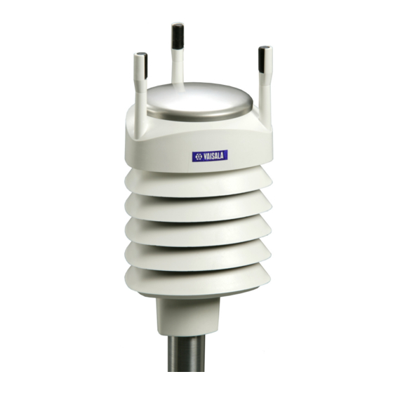
Chapter 2 __________________________________________________________ Product Overview CHAPTER 2 PRODUCT OVERVIEW This chapter introduces the unique features and advantages of the Vaisala Weather Transmitter WXT520. Weather Transmitter WXT520 Figure 1 Vaisala Weather Transmitter WXT520 0504-066 VAISALA _______________________________________________________________________ 17... -
Page 20: Heating Function
The transmitter housing is IP65/IP66 rated. WXT520 powers up with 5 ... 32 VDC and outputs serial data with a selectable communication protocol: SDI-12, ASCII automatic & polled and NMEA 0183 with query option. Four alternative serial interfaces are selectable: RS-232, RS-485, RS-422, and SDI-12. -
Page 21: Wxt520 Transmitter Components
Chapter 2 __________________________________________________________ Product Overview WXT520 Transmitter Components Figure 2 Main Components of Weather Transmitter WXT520 0804-021 The following numbers refer to Figure 2 on page Top of the transmitter Radiation shield Bottom of the transmitter Screw cover VAISALA _______________________________________________________________________ 19... -
Page 22: Figure 3 Cut Away View
User’s Guide ______________________________________________________________________ Figure 3 Cut Away View 0803-028 The following numbers refer to Figure 3 on page Wind transducers (3 pcs) Precipitation sensor Pressure sensor inside the PTU module Humidity and temperature sensors inside the PTU module 20 __________________________________________________________________ M210906EN-C... -
Page 23: Figure 4 Bottom Of Transmitter
Alignment direction sign 4-pin M8 connector for Service Port Water tight cable gland (optional, included in the Bushing and Grounding Kit) Opening for cable gland (if unused, cover with a hexagonal plug) 8-pin M12 connector for power/datacom cable (optional) VAISALA _______________________________________________________________________ 21... -
Page 24: Figure 5 Mounting Kit (Optional)
0505-193 The optional mounting kit can be used to ease the mounting of the WXT520 on a pole mast. When using the optional mounting kit, alignment is needed only when mounting for the first time. Using the mounting kit also improves the IP classification of the WXT520 to IP66. -
Page 25: Figure 7 Bird Spike Kit (Optional)
Note that when the kit is in place, more snow can accumulate on the transmitter, and the snow may melt slower. VAISALA _______________________________________________________________________ 23... -
Page 26: Figure 8 Surge Protector (Optional)
Vaisala wind and weather instruments. The WSP150 should be installed close to the protected instrument (max 3 m). Vaisala Surge Protector WSP152 is designed to be used with Vaisala WXT transmitters and WMT sensors, to protect the host PC against surges entering through the USB port. -
Page 27: Functional Description
Chapter 3 ______________________________________________________ Functional Description CHAPTER 3 FUNCTIONAL DESCRIPTION This chapter describes the measurement principles and heating function of Weather Transmitter WXT520. Wind Measurement Principle ® WXT520 uses Vaisala WINDCAP sensor technology in wind measurement. The wind sensor has an array of three equally spaced ultrasonic transducers on a horizontal plane. - Page 28 The wind speed is represented as a scalar speed in selected units (m/s, kt, mph, km/h). The wind direction is expressed in degrees (°). The wind direction reported by WXT520 indicates the direction that the wind comes from. North is represented as 0°, east as 90°, south as 180°, and west as 270°.
-
Page 29: Precipitation Measurement Principle
The WXT520 constantly monitors the wind measurement signal quality. If poor quality is detected, the wind values are marked as invalid. If over half of the measurement values can be considered as invalid, the last valid wind values are returned as missing data. - Page 30 User’s Guide ______________________________________________________________________ The sensor is also capable of distinguishing hails from raindrops. The measured hail parameters are cumulative amount of hails, current and peak hail intensity and the duration of a hail shower. The precipitation sensor operates in the following four modes: Precipitation Start/End mode: Transmitter sends automatically a precipitation message 10 seconds after the recognition of the first drop.
-
Page 31: Ptu Measurement Principle
Note that Th is measured inside the equipment, where temperature is much higher than the ambient temperature (Ta). Three fixed temperature limits, namely +4 °C, 0 °C, and -4 °C (+39 °F, +32 °F, +25 °F) control the heating as follows: VAISALA _______________________________________________________________________ 29... -
Page 32: Figure 9 Heating Control
User’s Guide ______________________________________________________________________ Figure 9 Heating Control 0806-010 The following example shows how heating behaves as Ta starts to fall: When Ta falls below +4 °C, heating is enabled. Heating keeps Th > +4 °C until Ta < -1 °C. Heating keeps Th >... -
Page 33: Chapter 4 Installation
This chapter provides you with information that is intended to help you install Weather Transmitter WXT520. Unpacking the Transmitter Weather Transmitter WXT520 comes in a custom shipping container. Be careful when removing the device from the container. CAUTION Beware of damaging any of the wind transducers located at the top of the three antennas. -
Page 34: Selecting The Location
The site should represent the general area of interest. Weather Transmitter WXT520 should be installed in a location that is free from turbulence caused by nearby objects, such as trees and buildings. In general, any object of height (h) will not remarkably disturb wind measurement at a minimum distance of 10 h. -
Page 35: Figure 11 Recommended Mast Length On Top Of A Building
(H), the minimum length of the mast is 1.5 W. WARNING To protect personnel (and the device), a lightning rod should be installed with the tip at least one meter above WXT520. The rod must be properly grounded, compliant with all applicable local safety regulations. -
Page 36: Installation Procedure
Mounting Weather Transmitter WXT520 can be mounted either onto a vertical pole mast or onto a horizontal cross arm. When mounting WXT520 onto a pole mast, an optional mounting kit can be used to ease mounting. When using the optional mounting kit, alignment is needed only when mounted for the first time. -
Page 37: Mounting With Mounting Kit (Optional)
Mount the adapter to the pole mast, do not tighten the fixing screw (provided). Align the transmitter in such a way that the arrow points to north. Tighten the fixing screw of the mounting adapter to fix the adapter firmly to the pole mast. VAISALA _______________________________________________________________________ 35... -
Page 38: Figure 13 Mounting Wxt520 To Pole Mast Using Optional Mounting
Figure 13 on page Mounting kit Fixing screw NOTE When removing WXT520 from the pole just turn the transmitter so that it snaps out from the mounting kit. When replacing the device the alignment is not needed. 36 __________________________________________________________________ M210906EN-C... -
Page 39: Mounting To Horizontal Cross Arm
(M6 DIN933) and a nut, see Figure 14 on page 37 Figure 15 on page Figure 14 Mounting WXT520 to Cross Arm (L-Profile) 0803-032 The following numbers refer to Figure 14 on page Nut (M6 DIN934) Mounting bolt (M6 DIN933) -
Page 40: Grounding The Wxt520
Mounting bolt (M6 DIN933) Grounding the WXT520 The normal way to ground the WXT520 is to install it on a mast or a cross arm that provides a good connection to earth ground. The grounding is provided via the fixing screw (or mounting bolt), so it is important that it makes a good ground connection. -
Page 41: Marine Grounding Jumper
Abiko connector between two washers Marine Grounding Jumper The WXT520 should be properly grounded also in marine applications. If it is grounded to the hull of a ship (ship’s ground) you must remove the grounding jumper inside the WXT520. When the jumper is removed, the signal ground is DC isolated from the chassis ground (>... -
Page 42: Figure 17 Grounding Jumper Location
To remove the jumper, you must open the transmitter. If you need to access the screw terminals, you should remove the jumper at the same time. Loosen the three long screws at the bottom of WXT520. Pull out the bottom part of the transmitter. Remove the grounding jumper from the PCB. -
Page 43: Aligning Wxt520
Aligning WXT520 To help the alignment, there is an arrow and the text "North" on the bottom of the transmitter. WXT520 should be aligned in such a way that this arrow points to the north. Wind direction can be referred either to true north, which uses the earth’s geographic meridians, or to the magnetic north, which is read... -
Page 44: Wind Direction Offset
User’s Guide ______________________________________________________________________ Wind Direction Offset Make a wind direction offset in case WXT520 cannot be aligned in such a way that the arrow on the bottom points to the north. In this case, the deviation angle from the true north should be given to WXT520. -
Page 45: Wiring And Power Management
WXT520 can be accessed through four different serial interfaces: RS- 232, RS-485, RS-422 and SDI-12. Each of them can be wired either through the internal screw terminal or the 8-pin M12 connector. Only one serial interface can be used at a time. -
Page 46: Figure 20 Average Operational Current Consumption
24 VDC ± 20 % (max 0.6 A). Maximum heating power is achieved at voltages 15.5 V and 32 V. Nominally at 15.7 V heating voltage level WXT520 automatically changes the heating element combination in order to consume equal 44 __________________________________________________________________ M210906EN-C... -
Page 47: Figure 21 Heating Current And Power Vs Vh
Heating Current and Power vs Vh 0805-22 WARNING Make sure that you connect only de-energized wires. CAUTION To avoid exceeding the maximum ratings in any condition, the voltages must be checked with no load at the power supply output. VAISALA _______________________________________________________________________ 45... -
Page 48: Wiring Using The 8-Pin M12 Connector
(operating) The signal names Data in (RxD) and Data out (TxD) in the table describe the direction of data flow as seen from WXT520. The terms "Default wiring" and "RS-422 wiring" refer to the two internal wiring options, see the diagrams on the next page. -
Page 49: Internal Wiring
Bidirectional use of the RS-485 and RS-422 interface requires a proper adapter module between the PC and WXT520. For testing purposes, the inverted output of either interface (screw terminal pin #3 TX-) is directly readable with PC's Received Data line. In this case Signal Ground for PC serial port is taken from screw terminal pin #6 SGND (for testing purposes pin #19 VIN- will also do). -
Page 50: Wiring Using The Screw Terminals
User’s Guide ______________________________________________________________________ Wiring Using the Screw Terminals Loosen the three long screws at the bottom of WXT520. Pull out the bottom part of the transmitter. Insert the power supply wires and signal wires through the cable gland(s) in the bottom of the transmitter. Cable glands are included in the optional Bushing and Grounding Kit (order code 222109). - Page 51 Vin+ (operating) NOTE In the true SDI-12 mode the two Data in/out lines must be combined either in the screw terminal or outside WXT520. NOTE Short-circuit jumpers are required between pins 1-3 and 2-4 for the RS-485 communication mode. For the RS-422 mode, the jumpers should be removed.
-
Page 52: Data Communication Interfaces
User’s Guide ______________________________________________________________________ Data Communication Interfaces Figure 25 Data Communication Interfaces 0505-206 With RS-485 and RS-422 interfaces, termination resistors should be used at both ends of the line, if data rate is 9600 Bd or higher and distance is 600 m (2000 ft) or longer. Resistor range 100 ... 180 suitable for twisted pair lines. -
Page 53: Power Management
100 m (300 ft) with 1200 Bd data rate. Higher rates require shorter distance, for instance 30 m (100 ft) with 9600 Bd. NOTE If you use the WXT520 on an RS-485 bus with other polled devices, always disable the error messaging feature. You can do this with the following command: 0SU,S=N<crlf>. - Page 54 User’s Guide ______________________________________________________________________ PTU measurement adds approximately 0.8 mA to the standby consumption. Each single measurement of PTU takes 5 seconds (including the warm-up period). This can be used for estimating the average consumption of PTU. Continuous precipitation adds some 0.07 mA to the standby consumption.
- Page 55 NOTE While in Service mode and/or while supplied through the Service port the WXT520 consumes 0.3 ... 0.6 mA more than in normal mode, when supplied through the Main port (M12 connector or screw terminals). When supplied through the Service port the minimum voltage level for reliable operation is 6V.
- Page 56 User’s Guide ______________________________________________________________________ 54 __________________________________________________________________ M210906EN-C...
-
Page 57: Chapter 6 Connection Options
This chapter contains instructions for configuring the communication with the transmitter. Communication Protocols As soon as WXT520 has been properly connected and powered the data transmission can be started. The communication protocols available in each of the serial interfaces are shown in the following table. -
Page 58: Connection Cables
WXT520. Connection cables The connection cable options for WXT520 are listed in the table below. The USB cables allow the transmitter to be connected to a PC using a standard USB port. The USB cables also provide operation power to the transmitter when connected. -
Page 59: Installing The Driver For The Usb Cable
COM port. There is no reason to uninstall the driver for normal use. However, if you wish to remove the driver files and all Vaisala USB cable devices, you can do so by uninstalling the entry for Vaisala USB Instrument Driver from the Add or Remove Programs (Programs and Features in Windows Vista) in the Windows Control Panel. -
Page 60: Service Cable Connection
The service cable connection is recommended for checking and changing the device settings. When making the changes, use the Vaisala Configuration Tool or a standard PC terminal program. The USB service cable is included in the Service Pack 2, see... -
Page 61: Connection Through M12 Bottom Connector Or Screw Terminal
Serial Interface Serial Settings SDI-12 1200 baud, 7, E, 1 RS-232, ASCII 19200 baud, 8, N, 1 RS-485, ASCII 19200 baud, 8, N, 1 RS-422 ASCII 19200 baud, 8, N, 1 RS-422 NMEA 4800 baud, 8, N, 1 VAISALA _______________________________________________________________________ 59... -
Page 62: Communication Setting Commands
See section Supervisor Message on page 123. The information field is set as part of the factory settings (see General Unit Settings on page 166). You can only modify it using the Vaisala Configuration Tool. 60 __________________________________________________________________ M210906EN-C... -
Page 63: Setting Fields
RS-485 line delay: 0 ... 10000 ms Defines the delay between the last character of the query and the first character of the response message from WXT520. During the delay, the WXT520's transmitter is disabled. Effective in ASCII, polled and NMEA 0183 query protocols. Effective when RS-485 is selected (C = 3). - Page 64 Chapter 8, Sensor and Data Message Settings, on page 107. The data is outputted on request. Example (ASCII and NMEA 0183, device address 0): 0XU<cr><lf> 0XU,A=0,M=P,T=0,C=2,I=0,B=19200,D=8,P=N,S=1,L=25, N=WXT520,V=1.00<cr><lf> Example (SDI-12, device address 0): 0XXU!0XXU,A=0,M=S,T=0,C=1,I=0,B=1200,D=7,P=E,S=1,L=25, N=WXT520,V=1.00<cr><lf> 62 __________________________________________________________________ M210906EN-C...
-
Page 65: Changing The Communication Settings (Axu)
1200, 7, E, 1 and the communication protocol to SDI-12 (M=S). NOTE Reset the transmitter to validate the changes of communication parameters by disconnecting the service cable or using the Reset (aXZ) command, see Reset (aXZ) on page VAISALA _______________________________________________________________________ 63... - Page 66 1XU,A=1<cr><lf> Checking the changed settings: 1XU<cr><lf> 1XU,A=1,M=P,T=1,C=2,I=0,B=19200,D=8,P=N,S=1,L=25, N=WXT520,V=1.00<cr><lf> Example (ASCII, device address 0): Changing RS-232 serial interface with ASCII, polled communication protocol and baud settings 19200, 8, N, 1 to RS-485 serial interface with ASCII, automatic protocol and baud settings 9600, 8, N, 1.
-
Page 67: Getting The Data Messages
Supv (M5): Th Vh Vs Vr Id Comp (M): Wind PTU Rain Supv (parameters in above order) The order of the parameters is fixed, but you can exclude any parameter from the list when configuring the transmitter. VAISALA _______________________________________________________________________ 65... -
Page 68: General Commands
General Commands In case the error messaging is disabled (see Supervisor Message on page 123), WXT520 does not return any response message with the general commands given in ASCII and NMEA-formats. Reset (aXZ) This command is used to perform software reset on the device. -
Page 69: Precipitation Counter Reset (Axzru)
Device address XZRU Precipitation counter reset command <cr><lf> Command terminator in ASCII and NMEA 0183 Command terminator in SDI-12 Example (ASCII): 0XZRU<cr><lf> 0TX,Rain reset<cr><lf> Example (SDI-12): 0XZRU!0<cr><lf> (= device address) Example (NMEA 0183): 0XZRU<cr><lf> $WITXT,01,01,10,Rain reset*26<cr><lf> VAISALA _______________________________________________________________________ 67... -
Page 70: Precipitation Intensity Reset (Axzri)
User’s Guide ______________________________________________________________________ Precipitation Intensity Reset (aXZRI) This command is used to reset the rain and hail intensity parameters Ri, Rp, Hi and Hp. Command format in ASCII and NMEA 0183: aXZRI<cr><lf> Command format in SDI-12: aXZRI! where Device address XZRI Precipitation intensity reset command <cr><lf>... -
Page 71: Measurement Reset (Axzm)
Command format in SDI-12: aXZM! where Device address Measurement break command <cr><lf> Command terminator in ASCII and NMEA 0183 Command terminator in SDI-12 Example (ASCII): 0XZM<cr><lf> 0TX,Measurement reset<cr><lf> Example (SDI-12): 0XZM!0 (= device address) Example (NMEA 0183): 0XZM<cr><lf> $WITXT,01,01,09,Measurement reset*50<cr><lf> VAISALA _______________________________________________________________________ 69... -
Page 72: Ascii Protocol
User’s Guide ______________________________________________________________________ ASCII Protocol This section presents the data commands and data message formats for the ASCII communication protocols. Abbreviations and Units For changing the units, see Chapter 8, Sensor and Data Message Settings, on page 107. Table 6 Abbreviations and Units Abbreviation Name... -
Page 73: Device Address (?)
This command is used to ensure that a device is responding to a data recorder or another device. It asks a device to acknowledge its presence on the bus. Command format: a<cr><lf> where Device address <cr><lf> Command terminator VAISALA _______________________________________________________________________ 71... -
Page 74: Wind Data Message (Ar1)
User’s Guide ______________________________________________________________________ The response: a<cr><lf> where Device address <cr><lf> Response terminator Example: 0<cr><lf> 0<cr><lf> Wind Data Message (aR1) With this command you can request the wind data message. Command format: aR1<cr><lf> where Device address Wind message query command <cr><lf> Command terminator Example of the response (the parameter set is configurable): 0R1,Dn=236D,Dm=283D,Dx=031D,Sn=0.0M,Sm=1.0M,... -
Page 75: Pressure, Temperature And Humidity Data Message
Relative humidity (P = % RH) Air pressure (H = hPa) <cr><lf> Response terminator To change the parameters and units in the response message and to make other sensor settings, see section Pressure, Temperature, and Humidity Sensors on page 113. VAISALA _______________________________________________________________________ 73... -
Page 76: Precipitation Data Message (Ar3)
User’s Guide ______________________________________________________________________ Precipitation Data Message (aR3) With this command you can request the precipitation data message. Command format: aR3<cr><lf> where Device address Precipitation message query command <cr><lf> = Command terminator Example of the response (the parameter set is configurable): 0R3,Rc=0.0M,Rd=0s,Ri=0.0M,Hc=0.0M,Hd=0s,Hi=0.0M,Rp=0.0M, Hp=0.0M<cr><lf>... -
Page 77: Supervisor Data Message (Ar5)
123. The content of the parameter "Id" is a text string which can be modified by using the Vaisala Configuration Tool only. Field can include customer-specific, additional information. For more information on changing the settings, refer to the Vaisala Configuration Tool on-line help for the Info field in the Device Settings window. -
Page 78: Combined Data Message (Ar)
User’s Guide ______________________________________________________________________ Combined Data Message (aR) With this command you can request all individual messages aR1, aR2, aR3 and aR5 with just one command. Command format: aR<cr><lf> where Device address (default = 0) Combined message query command <cr><lf> Command terminator Example of the response: 0R1,Dm=027D,Sm=0.1M<cr><lf>... -
Page 79: Polling With Crc
Example of the response (the parameter set is configurable): 0r1,Dn=236D,Dm=283D,Dx=031D,Sn=0.0M,Sm=1.0M,Sx=2.2MLFj <cr><lf> where the three characters before <cr><lf> are the CRC for the response. NOTE The correct CRC for each command can be requested by typing the command with an arbitrary three-character CRC. VAISALA _______________________________________________________________________ 77... - Page 80 User’s Guide ______________________________________________________________________ Example of asking the CRC for the wind data message query ar1: Command format: ar1yyy<cr><lf> where Device address Wind message query command Arbitrary three-character CRC <cr><lf> Command terminator Response: atX,Use chksum GoeIU~<cr><lf> where Device address tX,Use Text prompt chksum Correct three-character CRC for the ar1 command Three-character CRC for the response message...
-
Page 81: Automatic Mode
The message structure is the same as with the composite data query command aR0 and contains a user configurable set of wind, pressure, temperature, humidity, precipitation and supervisor data. VAISALA _______________________________________________________________________ 79... -
Page 82: Sdi-12 Protocol
Chapter 8, Sensor and Data Message Settings, on page 107. In the Native SDI-12 mode (aXU,M=S) the WXT520 is in idle state most of the time (power consumption < 1 mW). More power is consumed only during the measurements and data transmit requested by the host device. -
Page 83: Address Query Command (?)
This command is used to ensure that a device is responding to a data recorder or another SDI-12 device. It asks a device to acknowledge its presence on the SDI-12 bus. Command format: a! where Device address Command terminator VAISALA _______________________________________________________________________ 81... -
Page 84: Change Address Command (Aab)
User’s Guide ______________________________________________________________________ The response: a<cr><lf> where Device address <cr><lf> Response terminator Example: 0!0<cr><lf> Change Address Command (aAb) This command changes the device address. After the command has been issued and responded to, the sensor is not required to respond to another command for one second time in order to ensure writing the new address to the non-volatile memory. -
Page 85: Send Identification Command (Ai)
8-character serial number <cr><lf> Response terminator Example: 0I!013VAISALA_WXT520103Y2630000<cr><lf> Start Measurement Command (aM) This command asks the device to make a measurement. The measured data are not sent automatically and should be requested with a separate Send data command aD. VAISALA _______________________________________________________________________ 83... - Page 86 User’s Guide ______________________________________________________________________ The host device is not allowed to send any commands to other devices on the bus until the measurement is completed. When several devices are connected to the same bus and simultaneous measurements from the different devices are needed, Start concurrent measurement aC or Start concurrent measurement with CRC aCC should be used, see the next sections.
-
Page 87: Start Measurement Command With Crc (Amc)
107. NOTE When the measurement takes less than one second, the response part two is not sent. In WXT520 this is the case in the precipitation measurement aM3. NOTE The maximum number of parameters that can be measured with aM and aMC commands is nine (9). -
Page 88: Start Concurrent Measurement With Crc (Acc)
User’s Guide ______________________________________________________________________ Command format: aCx! where Device address Start concurrent measurement command The desired measurement 1 = Wind 2 = Temperature, humidity and pressure 3 = Precipitation 5 = Supervisor If x is left out, the query refers to combined data message in which the user can request data from several sensors with just one command. -
Page 89: Send Data Command (Ad)
Examples of aM, aC and aD Commands on page Command terminator The response: a+<data fields><cr><lf> where Device address <data The measured parameters in selected units, separated fields> with '+' marks (or - marks in case of negative parameter values). <cr><lf> Response terminator VAISALA _______________________________________________________________________ 87... -
Page 90: Examples Of Am, Ac And Ad Commands
User’s Guide ______________________________________________________________________ NOTE aD0 command can also be used to break the measurement in progress started with commands aM, aMC, aC or aCC. NOTE In SDI-12 v1.3 Continuous measurement mode (aXU,M=R) the sensor makes measurements at configurable update intervals. The aD command following the aM, aMC, aC or aCC command always returns the latest updated data. - Page 91 Due to the 35-character limit in response message, aD0 returns only six parameters. The remaining parameters are retrieved with aD1. 0M!00059<cr><lf> (measurement ready in 5 seconds and 9 parameters available) 0<cr><lf> (measurement completed) 0D0!0+340+0.1+23.7+27.9+1009.3+0.15<cr><lf> 0D1!0+0.0+0+0.0<cr><lf> VAISALA _______________________________________________________________________ 89...
-
Page 92: Continuous Measurement (Ar)
Chapter 8, Sensor and Data Message Settings, on page 107). NOTE For using Continuous measurement commands for all WXT520 parameters (wind, PTU, precipitation, and supervisor) the respective protocol must be selected (aXU,M=R). The M=S selection requires use of aM, aMC, aC, aCC + aD commands, only the precipitation data can be retrieved continuously (using aR3 command). - Page 93 '+' marks (or '-' marks in case of negative parameter values). The maximum number of parameters to be measured with one reqeust is 15. <cr><lf> Response terminator Examples (device address 0): 0R1!0+323+331+351+0.0+0.4+3.0<cr><lf> 0R3!0+0.15+20+0.0+0.0+0+0.0+0.0+0.0<cr><lf> 0R!0+178+288+001+15.5+27.4+38.5+23.9+35.0+1002.1+0.00+0+ 0.0+23.8<cr><lf> VAISALA _______________________________________________________________________ 91...
-
Page 94: Continuous Measurement With Crc (Arc)
Example (device address 0): 0RC3!0+0.04+10+14.8+0.0+0+0.0INy Start Verification Command (aV) This command is used to query self diagnostic data from the device. However, the command is not implemented in WXT520. The self- diagnostic data can be requested with aM5 command. 92 __________________________________________________________________ M210906EN-C... -
Page 95: Nmea 0183 V3.0 Protocol
Response terminator. Example: ?<cr><lf> 0<cr><lf> If more than one transmitter is connected to the bus, see Appendix A, Networking, on page 149. If you need to change the device address, see Changing the Communication Settings (aXU) on page VAISALA _______________________________________________________________________ 93... -
Page 96: Acknowledge Active Command (A)
User’s Guide ______________________________________________________________________ Acknowledge Active Command (a) This command is used to ensure that a device is responding to a data recorder or another device. It asks a sensor to acknowledge its presence on the bus. Command format: a<cr><lf> where Device address <cr><lf>... - Page 97 Chapter 8, section Wind Sensor. The checksum to be typed in the query depends on the device identifier characters. The correct checksum can be asked from WXT520 by typing any three characters after the $--WIQ,MWV command. VAISALA _______________________________________________________________________ 95...
-
Page 98: Xdr Transducer Measurement Query
User’s Guide ______________________________________________________________________ Example: Typing the command $--WIQ,MWVxxx<cr><lf> (xxx arbitrary characters) WXT520 responds $WITXT,01,01,08,Use chksum 2F*72<cr><lf> which tells that 2F is the correct checksum for the $--WIQ,MWV command. Example of the MWV Query: $--WIQ,MWV*2F<cr><lf> $WIMWV,282,R,0.1,M,A*37<cr><lf> (Wind angle 282 degrees, Wind speed 0.1 m/s) - Page 99 Units of the transducer n measurement, see the following transducer table. c--cn Transducer n id. WXT520's address aXU,A is added as a base number to the Transducer #ID. The address is changeable, see command aXU,A= [0 ... 9/A ... Z/ a ...
-
Page 100: Table 7 Transducer Ids Of The Measurement Parameters
A+1 for hails. Rain and hail peak intensities are assigned with transducer ids A+2 and A+3, respectively. For example, for a WXT520 with device address 0 the transducer ids of all the measurement parameters are as follows: Table 7... - Page 101 Example of the response when all the parameters of each sensor are enabled (NMEA wind formatter set to T): Wind sensor data $WIXDR,A,302,D,0,A,320,D,1,A,330,D,2,S,0.1,M,0,S,0.2,M,1,S,0.2, M,2*57<cr><lf> P, T, and RH data $WIXDR,C,23.3,C,0,C,24.0,C,1,H,50.1,P,0,P,1009.5,H, 0*75<cr><lf> Precipitation data $WIXDR,V,0.02,M,0,Z,30,s,0,R,2.7,M,0,V,0.0,M,1,Z,0,s,1,R,0.0,M,1, R,6.3,M,2,R,0.0,M,3*51<cr><lf> Supervisor data $WIXDR,C,20.4,C,2,U,12.0,N,0,U,12.5,V,1,U,3.460,V,2,G,HEL/ ___,,4*2D VAISALA _______________________________________________________________________ 99...
- Page 102 User’s Guide ______________________________________________________________________ The structure of the wind sensor response message: where Start of the message Device type (WI = weather instrument) Transducer measurement response identifier Transducer id 0 type (wind direction), see the following Transducer table Transducer id 0 data (min wind direction) Transducer id 0 units (degrees, min wind direction) Transducer id for min wind direction Transducer id 1 type (wind direction)
- Page 103 Transducer id 0 data (Pressure) Transducer id 0 units (hPa, Pressure) Transducer id for Pressure Checksum delimiter Two-character checksum for the response <cr><lf> Response terminator The structure of the precipitation sensor response message: where Start of the message VAISALA ______________________________________________________________________ 101...
- Page 104 User’s Guide ______________________________________________________________________ Device type (WI = weather instrument) Transducer measurement response identifier Transducer id 0 type (Accumulated rainfall), see the following Transducer table 0.02 Transducer id 0 data (Accumulated rainfall) Transducer id 0 units (mm, Accumulated rainfall) Transducer id for Accumulated rainfall Transducer id 0 type (Rain duration) Transducer id 0 data (Rain duration) Transducer id 0 units (s, Rain duration)
- Page 105 Transducer id 2 data (3.5V reference voltage) Transducer id 2 units (V, 3.5V reference voltage) Transducer id for 3.5V reference voltage Transducer id 4 type (generic) HEL/___ Transducer id 4 data (info field) Transducer id 4 units (none, null) VAISALA ______________________________________________________________________ 103...
-
Page 106: Txt Text Transmission
User’s Guide ______________________________________________________________________ Transducer id for generic field Checksum delimiter Two-character CRC for the response. <cr><lf> Response terminator 1. See Chapter 8, section Supervisor Message, Setting Fields for definitions of the Heating voltage field. Table 8 Transducer Table Transducer Type Units Field Comments Temperature... - Page 107 Response terminator Examples: $WItXT,01,01,01,Unable to measure error*6D<cr><lf> (wind data request when all the wind parameters were disabled from the wind message). $WITXT,01,01,03,Unknown cmd error*1F (unknown command 0XO!<cr><lf>). $WITXT,01,01,08,Use chksum 2F*72 (wrong checksum used in MWV query command) VAISALA ______________________________________________________________________ 105...
-
Page 108: Automatic Mode
User’s Guide ______________________________________________________________________ Automatic Mode When NMEA 0183 v3.0 automatic protocol is selected, the transmitter sends data messages at user configurable update intervals. The message format is the same as in the MWV and XDR data queries. The NMEA wind formatter parameter in the wind sensor settings determines whether the wind messages are sent in MWV or XDR format. -
Page 109: Sensor And Data Message Settings
ASCII, NMEA 0183 and SDI-12. Sensor and data message settings can also be done by using the Vaisala Configuration Tool software.With this software tool you can change the device and sensor settings easily in Windows® environment. See... - Page 110 User’s Guide ______________________________________________________________________ where Device address Wind sensor settings command in ASCII and NMEA 0183 Wind sensor settings command in SDI-12 <cr><lf> Command terminator in ASCII and NMEA 0183 Command terminator in SDI-12 The response in ASCII and NMEA 0183: aWU,R=[R],I=[I],A=[A],G=[G],U=[U],D=[D],N=[N],F=[F]<cr>...
-
Page 111: Setting Fields
Defines the period over which the wind speed and direction averaging is calculated. Same period is also used for maximum and minimum calculation. See also Appendix D Wind Measurement Averaging Method on page 163 for difference in averaging practices when A<I and A>I. VAISALA ______________________________________________________________________ 109... - Page 112 User’s Guide ______________________________________________________________________ Wind speed max/min calculation mode: 1 or 3 seconds G =1: Traditional max/min calculation is performed both for speed and direction. G =3: Gust & lull are calculated for wind speed, while direction calculation is as it is with G =1. the output messages, gust &...
-
Page 113: Changing The Settings (Awu)
NOTE If averaging time [A] is greater than update interval [I], it shall be a whole multiple of the update interval and at maximum 12 times greater. Example: If I = 5 s, A = 60 s. VAISALA ______________________________________________________________________ 111... - Page 114 User’s Guide ______________________________________________________________________ Examples (ASCII and NMEA 0183, device address 0): You need a 20-second averaging time for wind speed and direction both in wind data and composite data message in every 60 seconds. Wind speed shall be in knots and wind direction offset +10°. Changing the measurement interval to 60 seconds: 0WU,I=60<cr><lf>...
-
Page 115: Pressure, Temperature, And Humidity Sensors
The response in ASCII and NMEA 0183: aTU,R=[R],I=[I],P=[P],H=[H]<cr><lf> The response in SDI-12: aXTU,R=[R],I=[I],P=[P],H=[H]<cr><lf> where [R][I][P][H] are the setting fields, see the following section. Example (ASCII and NMEA 0183, device address 0): 0TU<cr><lf> 0TU,R=11010000&11010000,I=60,P=H,T=C<cr><lf> Example (SDI-12, device address 0): 0XTU!0XTU,R=11010000&11010000,I=60,P=H,T=C<cr><lf> VAISALA ______________________________________________________________________ 113... -
Page 116: Setting Fields
User’s Guide ______________________________________________________________________ Setting Fields Parameter selection: This field consists of 16 bits defining the PTU parameters included in the data messages. The bit value 0 disables and the bit value 1 enables the parameter. The bits 1-8 determine the 1st bit (most left) Pa Air pressure parameters included in the... -
Page 117: Changing The Settings (Atu)
Examples (ASCII and NMEA 0183, device address 0): You need the temperature and humidity data to be available in every 30 seconds Changing the parameter selection: 0TU,R=0101000001010000<cr><lf> 0TU,R=01010000&01010000<cr><lf> NOTE Character '&' is not allowed in the command. VAISALA ______________________________________________________________________ 115... - Page 118 User’s Guide ______________________________________________________________________ Changing the update interval: 0TU,I=30<cr><lf> 0TU,I=30<cr><lf> The response after the change: 0R2<cr><lf> 0R2,Ta=23.9C,Ua=26.7P<cr><lf> Example (SDI-12, device address 0): Changing the temperature unit to Fahrenheit: 0XTU,U=F!0<cr><lf> In SDI-12 mode a separate enquiry (0XTU!) must be given to check the data content.
-
Page 119: Precipitation Sensor
The response in ASCII and NMEA 0183: aRU,R=[R],I=[I],U=[U],S=[S],M=[M],Z=[Z],X=[X],Y=[Y]<cr> <lf> The response in SDI-12: aXRU,R=[R],I=[I],U=[U],S=[S],M=[M],Z=[Z],X=[X],Y=[Y]<cr> <lf> where [R][I][U][S][M][Z][X][Y] are the setting fields, see the following section. Example (ASCII and NMEA 0183, device address 0): 0RU<cr><lf> 0RU,R=11111100&10000000,I=60,U=M,S=M,M=R,Z=M,X=100, Y=100<cr><lf> Example (SDI-12, device address 0): 0RU!0RU,R=11111100&10000000,I=60,U=M,S=M,M=R, Z=M,X=100,Y=100<cr><lf> VAISALA ______________________________________________________________________ 117... -
Page 120: Setting Fields
User’s Guide ______________________________________________________________________ Setting Fields Parameter selection: This field consists of 16 bits defining the precipitation parameters included in the data messages. The bit value 0 disables and the bit value 1 enables the parameter. The parameter order is shown in the following table: The bits 1-8 determine the 1st bit (most left) Rc Rain amount... - Page 121 The overflow limits (x, y) are defined with the commands aRU,X=x for rain counter and aRU,Y=y for hail counter. Y = immediate reset: The counts are reset immediately after receiving the command. VAISALA ______________________________________________________________________ 119...
- Page 122 User’s Guide ______________________________________________________________________ Rain accumulation limit : 100...65535. Sets the rain accumulation counter resetting limit. When the value exceeds the limit, the counter is reset to zero. If the precipitation unit aRU,U=x is metric, the limit corresponds the range between 1.00 …655.35 mm.
-
Page 123: Changing The Settings (Aru)
M, Z, X, Y Fields on page 118. Input value for the setting <cr><lf> Command terminator in ASCII and NMEA 0183 Command terminator in SDI-12 Examples (ASCII and NMEA 0183): Changing the precipitation units to imperial: 0RU,U=I<cr><lf> 0RU,U=I<cr><lf> VAISALA ______________________________________________________________________ 121... - Page 124 User’s Guide ______________________________________________________________________ Changing the autosend mode to the tipping bucket mode: 0RU,M=C<cr><lf> 0RU,M=C<cr><lf> Making the Rain amount Rc and Rain intensity Ri available both in the precipitation message and composite data message: 0RU,R=1010000010100000<cr><lf> 0RU,R=10100000&10100000<cr><lf> The response after the change: 0R3<cr><lf>...
-
Page 125: Supervisor Message
Supervisor settings command in ASCII and NMEA 0183 Supervisor settings command in SDI-12 <cr><lf> Command terminator in ASCII and NMEA 0183 Command terminator in SDI-12 The response in ASCII and NMEA 0183: aSU,R=[R],I=[I],S=[S],H=[Y]<cr><lf> The response in SDI-12: aXSU,R=[R],I=[I],S=[S],H=[Y]<cr><lf> VAISALA ______________________________________________________________________ 123... -
Page 126: Setting Fields
User’s Guide ______________________________________________________________________ Setting Fields Parameter selection: This field consists of 16 bits defining the supervisor parameters included in the data messages. The bit value 0 disables and the bit value 1 enables the parameter. The bits 1-8 determine the 1st bit (most left) Th Heating temperature parameters included in the... -
Page 127: Changing The Settings (Asu)
Command format in SDI-12; aXSU,R=x,I=x,S=x,H=x! where R, I, S, H The supervisor setting fields, see Setting Fields on page 124. Value for the setting <cr><lf> Command terminator in ASCII and NMEA 0183 Command terminator in SDI-12 VAISALA ______________________________________________________________________ 125... - Page 128 User’s Guide ______________________________________________________________________ Example (ASCII and NMEA 0183, device address 0): Disabling the heating and error messaging: 0SU,S=N,H=N<cr><lf> 0SU,S=N,H=N<cr><lf> Example (SDI-12, device address 0): Changing the update interval to 10 seconds: 0XSU,I=10!0<cr><lf> In SDI-12 mode a separate enquiry (0XSU!) must be given to check the data content.
-
Page 129: Composite Data Message (Ar0)
(Dm) and average wind speed (Sm): 0WU,R=&01001000<cr><lf> 0WU,R=11110000&01001000<cr><lf> Remove the heating voltage (Vh) and temperature (Th) data from the composite data message, and include the information field (Id): 0SU,R=&00001000<cr><lf> 0SU,R=11110000&00001000<cr><lf> Remove the accumulated rainfall (Rc) from the composite data message: 0RU,R=&00000000<cr><lf> 0RU,R=11111100&00000000<cr><lf> VAISALA ______________________________________________________________________ 127... - Page 130 User’s Guide ______________________________________________________________________ The final composite data message query and response in ASCII: 0R0<cr><lf> 0R0,Dm=009D,Sm=0.2M,Ta=23.3C,Ua=37.5P, Pa=996.8H,Id=HEL___<cr><lf> 128 _________________________________________________________________ M210906EN-C...
-
Page 131: Chapter 9 Maintenance
Cleaning To ensure the accuracy of measurement results, Weather Transmitter WXT520 should be cleaned when it gets contaminated. Leaves and other such particles should be removed from the precipitation sensor and the transmitter should be cleaned carefully with a soft, lint-free cloth moistened with mild detergent. -
Page 132: Replacing The Ptu Module
User’s Guide ______________________________________________________________________ Replacing the PTU Module Turn the power off. Loosen the three fixing screws at the bottom assembly of the WXT520. Turn out the top of the transmitter. Release the small white latch (see section A in Figure 26 on page 130) and remove the PTU module. -
Page 133: Factory Calibration And Repair Service
Phone: +81 3 3266 9617, Fax: +81 3 3266 9655 E-mail: aftersales.asia@vaisala.com BEIJING SERVICE CENTER Vaisala China Ltd., Floor 2 EAS Building, No. 21 Xiao Yun Road, Dongsanhuan Beilu, Chaoyang District, Beijing, P.R. CHINA 100027. Phone: +86 10 8526 1199, Fax: +86 10 8526 1155 E-mail: china.service@vaisala.com... - Page 134 User’s Guide ______________________________________________________________________ 132 _________________________________________________________________ M210906EN-C...
-
Page 135: Chapter 10 Troubleshooting
Ensure the proper connection of temperature measurement properly connected. the PTU module. failure. The unit is replaced by a There may be water in the PTU Remove and dry the module. # sign or the data values are module. irrelevant. VAISALA ______________________________________________________________________ 133... -
Page 136: Table 10 Communication Problems
A command mistyped in ASCII/ Getting the Data Messages, on NMEA mode while error page messaging/text messages is Enable the error messaging disabled (aSU,S=N). using the Vaisala Configuration Tool or any terminal by setting aSU,S=Y, then try the command again. 134 _________________________________________________________________ M210906EN-C... -
Page 137: Self-Diagnostics
Self-Diagnostics Error Messaging/Text Messages WXT520 sends a text message when certain type of errors occur. This function works in all communication modes except in the SDI-12 mode. You may disable error messaging by using the supervisor message aSU, S=N, see Changing the Settings (aSU) on page 125. -
Page 138: Table 11 Error Messaging/Text Messages Table
Vaisala Service Center, see Vaisala Service Centers on page 131. NOTE When WXT520 is used on an RS-485 bus with other polled devices, the error messaging feature shall always be disabled. This is done by the following command: 0SU,S=N<crlf>. 136 _________________________________________________________________ M210906EN-C... -
Page 139: Rain And Wind Sensor Heating Control
(Vs). In case of deviations between the supplied voltage and monitored voltage, check the wiring and the power supply. Technical Support For technical questions, contact the Vaisala technical support: E-mail helpdesk@vaisala.com +358 9 8949 2790... - Page 140 User’s Guide ______________________________________________________________________ 138 _________________________________________________________________ M210906EN-C...
-
Page 141: Technical Specifications
-52 ... +60 °C (-60 ... +140 °F) Accuracy (for sensor element) ±0.3 °C at +20 °C (+68 °F) For accuracy over temperature range, see the following graph Output resolution 0.1 °C (0.1 °F) Units available °C, °F VAISALA ______________________________________________________________________ 139... -
Page 142: Figure 27 Accuracy Over Temperature Range
User’s Guide ______________________________________________________________________ °C °C -0.1 -0.2 -0.3 -0.4 -0.5 -0.6 -0.7 Figure 27 Accuracy Over Temperature Range 0505-209 Table 14 Wind Property Description/Value Wind speed range 0 ... 60 m/s response time 0.25 s available variables average, maximum, and minimum accuracy ±3 % at 10 m/s output resolution... -
Page 143: Table 16 Precipitation
1. Due to the nature of the phenomenon, deviations caused by spatial variations may exist in precipitation readings, especially in short time scale. The accuracy specification does not include possible wind induced error. VAISALA ______________________________________________________________________ 141... -
Page 144: Inputs And Outputs
User’s Guide ______________________________________________________________________ Inputs and Outputs Table 17 Inputs and Outputs Property Description/Value Operating voltage 5 ... 32 VDC Average current consumption minimum 0.1 mA @ 12 VDC (SDI-12 standby) typical 3 mA @ 12 VDC (with default measuring intervals) maximum 14 mA @ 5 VDC (with constant measurement of all parameters) -
Page 145: Operating Conditions
IEC 61000-4-6 Conducted RF immunity 1. A = Normal performance B = Temporary degradation (self-recoverable) C = Temporary degradation (operator intervention needed) D = not recoverable 2. Within frequency range 600 ... 700 MHz immunity for PTU is 8 V/m VAISALA ______________________________________________________________________ 143... -
Page 146: Materials
User’s Guide ______________________________________________________________________ Materials Table 20 Materials Property Description/Value Radiation shield, top, and Polycarbonate + 20 % glass fibre bottom parts Precipitation sensor plate Stainless steel (AISI 316) Weight 650 g (1.43 lbs.) General Table 21 General Property Description/Value Self-diagnostic Separate supervisor message, unit/status fields to validate measurement stability Start-up... -
Page 147: Options And Accessories
Chapter 11 ____________________________________________________ Technical Specifications Options and Accessories Table 22 Options and Accessories Description Order code Service Pack 2: Vaisala Configuration Tool 220614 software and USB service cable USB service cable adapter for WXT510/ 221523 WMT50 USB RS-232/RS-485 cable M12 female... -
Page 148: Dimensions (Mm/Inch)
User’s Guide ______________________________________________________________________ Dimensions (mm/inch) Figure 28 WXT520 Dimensions, Side View 0803-040 146 _________________________________________________________________ M210906EN-C... -
Page 149: Figure 29 Wxt520 Dimensions, Top And Bottom View
Chapter 11 ____________________________________________________ Technical Specifications Figure 29 WXT520 Dimensions, Top and Bottom View 0805-013 VAISALA ______________________________________________________________________ 147... -
Page 150: Figure 30 Mounting Kit Dimensions
User’s Guide ______________________________________________________________________ Figure 30 Mounting Kit Dimensions 0505-211 The following numbers refer to Figure 23 on page 120: Mounting kit with adapter sleeve for ø26.7 mm mast tube Mounting kit without adapter sleeve for ø30 mm mast tube 148 _________________________________________________________________ M210906EN-C... -
Page 151: Appendix Anetworking
In the data logger end, combine the "GND for data" wires of each WXT520 to the logger "GND for data" wire. Connect the "Data in/ out" wires of each WXT520 to the logger "Data" wire. -
Page 152: Communication Protocol
... ). Thereafter WXT520s on the bus do not respond to the commands not assigned to them nor to the data messages sent by the other WXT520s. Example (A bus with three WXT520s): WXT520 #1 communication settings: 0XXU,A=0,M=S,C=1,B=1200,D=7,P=E,S=1, L=25 WXT520 #2 communication settings: 1XXU,A=1,M=S,C=1,B=1200,D=7,P=E,S=1, L=25... -
Page 153: Rs-485 Serial Interface
Wiring and Power Management, on page In the data logger end, combine the "Data +" wires of each WXT520 to the logger "Data +" wire. Connect the "Data-" wires of each WXT520 to the logger "Data -" wire. Communication Protocol Set the communication protocol to ASCII polled (with or without CRC) or NMEA query. -
Page 154: Nmea 0183 V3.0, Query
0XU,A=0,M=Q,C=3,I=0,B=4800,D=8,P=N,S=1,L=2000 Now, when the XDR-query command $--WIQ,XDR*2D<cr><lf> is sent, WXT520 #1 responds after 25 ms, WXT520 #2 after 1000 ms and WXT520 #3 responds after 2000 ms. The sufficient delays depend on the maximum number of characters in the response messages and the baud rate. - Page 155 For the transducer IDs, see NMEA 0183 V3.0 Protocol on page The maximum transducer ID is three when WXT520 address is 0. Hence, assigning address 4 for the second and address 8 for the third WXT520 on the bus the following responses to the XDR-query $-- WIQ,XDR*2D<cr><lf>...
-
Page 156: Nmea 0183 V3.0 Query With Ascii Query Commands
IDs in the NMEA XDR messages can only be numbers. The addresses given in letters will show in the transducer IDs in the following way: WXT520 address = A => transducer ID = 10, B => 11, a => 36, b => 37 etc. - Page 157 Appendix A ______________________________________________________________ Networking $WIXDR,C,24.0,C,0,C,25.2,C,1,H,47.4,P,0,P,1010.1,H, 0*54<cr><lf> $WIXDR,V,0.000,I,0,Z,10,s,0,R,0.01,I,0,V,0.0,M,1,Z,0,s,1,R,0.0,M, 1*51<cr><lf> $WIXDR,C,25.8,C,2,U,10.7,N,0,U,10.9,V,1,U,3.360,V,2*7D<cr><lf> The query for WXT520 #2 and the response: 1R<cr><lf> $WIXDR,A,330,D,1,A,331,D,2,A,333,D,3,S,0.1,M,1,S,0.1,M,2,S,0.2, M,3*55<cr><lf> $WIXDR,C,23.5,C,1,C,24.3,C,2,H,49.3,P,1,P,1010.1,H, 1*59<cr><lf> $WIXDR,V,0.000,I,1,Z,0,s,1,R,0.00,I,1,V,0.0,M,2,Z,0,s,2,R,0.0,M, 2*67<cr><lf> $WIXDR,C,25.8,C,3,U,10.6,N,1,U,10.9,V,1,U,3.362,V,2*78<cr><lf> The query for WXT520 #3 and the response: 2R<cr><lf> $WIXDR,A,341,D,2,A,347,D,3,A,357,D,4,S,0.1,M,2,S,0.2,M,3,S,0.2, M,4*53<cr><lf> $WIXDR,C,23.5,C,2,C,24.3,C,3,H,49.3,P,2,P,1010.1,H, 2*5F<cr><lf> $WIXDR,V,0.000,I,2,Z,0,s,2,R,0.00,I,2,V,0.0,M,3,Z,0,s,3,R,0.0,M, 3*61<cr><lf>...
- Page 158 User’s Guide ______________________________________________________________________ 156 _________________________________________________________________ M210906EN-C...
-
Page 159: Sdi-12 Protocol
12-volt line. The SDI-12 bus can have at least 10 sensors connected to it. The bus topology is a parallel connection, where each of the three wires of different sensors are connected in parallel. VAISALA ______________________________________________________________________ 157... -
Page 160: Sdi-12 Communications Protocol
User’s Guide ______________________________________________________________________ SDI-12 Communications Protocol SDI-12 data recorders and sensors communicate by an exchange of ASCII characters on the data line. The data recorder sends a break to wake up the sensors on the data line. A break is continuous spacing on the data line for at least 12 milliseconds. -
Page 161: Sdi-12 Timing
100 milliseconds after detecting a break. After a data recorder transmits the last character of a command, it must relinquish control of the data line within 7.5 milliseconds. Figure 31 Timing Diagram 0505-218 VAISALA ______________________________________________________________________ 159... - Page 162 User’s Guide ______________________________________________________________________ After receiving the break and the command, the addressed sensor sets the data line to marking at 8.33 milliseconds and then sends the response (tolerance: -0.40 milliseconds.) The start bit of the first response byte must start within 15 milliseconds after the stop bit of the last byte of the command (tolerance: +0.40 milliseconds).
-
Page 163: Crc-16 Computation
=1 to 8 if the least significant bit of the CRC is one right shift the CRC one bit set CRC equal to the exclusive OR of 0xA001 and itself else right shift the CRC one bit VAISALA ______________________________________________________________________ 161... -
Page 164: Encoding The Crc As Ascii Characters
User’s Guide ______________________________________________________________________ Encoding the CRC as ASCII Characters The 16 bit CRC is encoded to three ASCII characters by using the following algorithm: 1st character = 0x40 OR (CRC shifted right 12 bits) 2nd character = 0x40 OR ((CRC shifted right 6 bits) AND 0x3F) 3rd character = 0x40 OR (CRC AND 0x3F) The three ASCII characters are placed between the data and <cr><lf>. -
Page 165: Wind Measurement Averaging Method
Wind measurement sampling rate (4, 2, or 1 Hz) does not have any effect on the averaging scheme. It determines from how many samples the one second values seen in the figures are calculated. VAISALA ______________________________________________________________________ 163... -
Page 166: Figure 32 Wind Measurement Averaging Method
User’s Guide ______________________________________________________________________ Case 1 I > A, all comm unication p rotocols other than SDI-12 (aXU,M=S). In this example I=5 sec and A=3 sec. time 1 sec Case 2 I < A, all comm unication p rotocols other than SDI-12 (aXU,M=S). In this example I=2 sec and A=5 sec. time 1 sec Case 3... -
Page 167: Factory Configurations
The factory configurations are read-only settings which cannot be modified. For each settings command, the following information is shown: the command to retrieve the settings (ends to ! character) an example response from the WXT a table describing the messsage contents VAISALA ______________________________________________________________________ 165... -
Page 168: General Unit Settings
User’s Guide ______________________________________________________________________ General Unit Settings 0XF!0XF,f=11111111&11100010,o=AAC1DB1A,c=A263, i=HEL___,n=A3430012,2=2528,3=3512 <cr><lf> Table 23 General Unit Settings Field Character Field Name Description Factory options Selection of parameters Order code Ordering identity as delivered (10 characters) Calibration date Y=2003, A, B,…=2005, 2006, 1..52 = week, 1...7, weekday Info Factory signature (10 characters) -
Page 169: Ptu Configuration Settings
Direct ADC value of temp.diode 0...4096 Defrosting limit w. 50% duty -100.0 ...[m] °C (default -4.0 °C) cycle Heating limit w. full power [l]...[h] °C(default 0.0 °C) Heating limit w. 50% duty cycle [m]...100.0 °C (default 4.0 °C) VAISALA ______________________________________________________________________ 167... - Page 170 User’s Guide ______________________________________________________________________ 168 _________________________________________________________________ M210906EN-C...
- Page 171 *M210906EN*...