Table of Contents
Advertisement
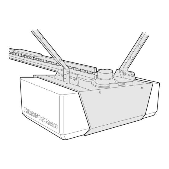
Owner's
Manual
Model No.
139.53662SRT2
139.53670SRT1
139.53675SRT2
For Residential Use
Only
Caution:
Read and follow
all
safety rules and
operating
instructions
before first use of this
product.
Fasten the manual
near the garage door
after installation.
Complies with UL 325 fllll
_
regulations effective
January 1, 1993
CRRFTSMRN
GARAGE DOOR OPENER
1/2 HP
[] Safety Precautions
[] Assembly
[] Installation
[] Adjustment
[] Care and Maintenance
[] Operation
[] Troubleshooting
[] Parts List
Sears, Roebuck
and Co., Hoffman
Estates,
IL 60179 U.S.A.
Advertisement
Table of Contents

Related Manuals for Craftsman 139.53662SRT2


Summary of Contents for Craftsman 139.53662SRT2
- Page 1 Owner's Manual Model No. 139.53662SRT2 139.53670SRT1 139.53675SRT2 For Residential Use Only CRRFTSMRN GARAGE DOOR OPENER 1/2 HP [] Safety Precautions Caution: [] Assembly Read and follow [] Installation safety rules and [] Adjustment operating instructions before first use of this [] Care and Maintenance product.
-
Page 2: Table Of Contents
Contents Page Contents Page A review of safety alert symbols ......... 2 Install the lights and lenses ........19 You'll need tools ............3 Attach emergency release rope and handle ... 19 Safety information regarding garage door Electrical requirements ..........20 locks and ropes ............ -
Page 3: You'll Need Tools
You'll Need Tools During assembly, installation and adjustment of the opener, instructions will call for hand tools shown below. Pencil _oooo o I_ Level Hack Saw Tape Measure Wire Cutters Ctaw Hammer _3/16", 5/16" 5/32" DritI Bits Stepladder Screwdriver Adjustable End Wrench An unbalanced garage door might not reverse To avoid... -
Page 4: Illustration Of Sectional Door Installation
Before you begin, survey your garage area to see whether any of the conditions below apply to your installation. FINISHED CEILING Support bracket & fastening hardware is required. Horizontal and vertical reinforcement See page 17 is needed for lightweight garage doors Slack in Chain Tension (fiberglass, steel, aluminum,... -
Page 5: Illustration Of One-Piece Door Installation
One-Piece Door without Track Before you begin, survey your garage area to FINISHED CEILING see whether any of the conditions below apply Support bracket to your installation. & fastening hardware is required. See page 17. Slack in chain tension is normal when garage door is closed, Header Wall... -
Page 6: Carton Inventory
Carton Inventory Your garage door opener is packaged in two cartons which contain parts illustrated below. Accessories will depend on model purchased. If anything is missing, carefully check the packing material. Parts may be "stuck" in the foam. Hardware for assembly and installation is shown on page 7. AII Models ModeI 53675 only ModeIs 53662 (2), 53670 (1),... -
Page 7: Hardware Inventory
Separate all hardware from the packages in the rail carton and the opener carton, shown below, for the assembly and installation procedures. Assembly Hardware Washered Screw Hex Screw Carriage Bolts 5/161-18xl/2" 5/16"-18x7/8" 5/16"-18 (5) Master Link (2) 1/4"-20xl/2"(4) (mounted in opener) ©... -
Page 8: Assembly Section: Pages
Assembly Section: Pages 8 - 11 To avoid installation difficulties, do not run the garage door opener until instructed to do so. Make sure bolt necks are Assembly Step 1 seated in the square holes and rails are Assemble the T-rail & aligned before Attach the Cable Pulley Bracket... -
Page 9: Install Trolley
Hardware Shown Assembly Step 2 Actual Size Install the Trolley on the T-rail © • Attach the threaded shaft to the trolley with the lock washer and nuts as shown. Lock Washer 5/16" 5/16"-18 Lock Washer Outer Nat Trotley Threaded Shaft Inner Nut 5/16"... -
Page 10: Install Chain/Cable
Assembly Step 4 Install the Chain/Cable & Attach the Sprocket Cover Serious injury can result if fingers become entangled in moving opener sprocket. Attach sprocket cover securely. Never operate opener while your hand is near the opener sprocket. Dispensing Carton Opener Figure 2 Sprocket... -
Page 11: Tighten The Chain And Cable
Assembly Step 5 Tighten the Chain & Cable Lock Outer Nut Washer Inner Nut • Spin the inner nut and lock washer down the threaded shaft, away from the trolley. To Tighten Outer Nut _ _-"-_ _, / • To tighten the chain, turn outer nut in the direction shown. -
Page 12: Installation Section: Pages
Installation Section: Pages 12 - 27 Installation Step 1 Determine Header Bracket Location If the header bracket is not rigidly fastened Installation procedures vary according a structural support on the header wall garage door types. Follow the instructions ceiling, the safety reverse system may not... -
Page 13: One-Piece Door
Read the Safety instructions on page 12. They also apply to doors without tracks. Unfinished Header Wall Vertical Centedine • Close the door and mark the inside vertical centerline of your garage door. Extend the line onto the header wall above door. -
Page 14: Install The Header Bracket
You can attach the header bracket either to the Installation Step 2 wall above the garage door, or to the ceiling, Follow the instructions which will work best for Install the Header Bracket your particular requirements. Fasten the Header Bracket to the Wall •... -
Page 15: Attach The T-Rail To Header Bracket
Installation Step 3 Attach the T-rail to the Header Bracket • Position the opener on the garage floor below the header bracket. Use packing material as a protective base. If the door spring is in the way you'll need help. Header Bracket Have someone hold the opener securely on a... -
Page 16: Position The Opener
Installation Step 4 Position the Opener Follow instructions which apply to your door type as illustrated. A 2x4 laid fiat is convenient for setting an ideal door-to-T-rail distance. Laid Fiat • Raise the opener onto a stepladder. You will need help at this point if the ladder is not tall enough. -
Page 17: Hang The Opener
Installation Step 5 Hang the Opener Two representative installations are shown. Yours may be different. Hanging brackets should be angled, Figure 1, to provide rigid support. On Figure 1 finished ceilings, Figure 2, attach a sturdy metal bracket to structural supports before installing the opener. -
Page 18: Install The Door Control
Installation Step 6 Install the Premium Control Console Do not connect to five electrical wiring. Connect only to 24 Volt low voltage wires. Connection to Locate the door control within sight of the door five wires or higher voltage may cause serious at a minimum height of 5 feet where small injury from shock, burn or electrocution. -
Page 19: Install The Lights And Lenses
6.AttachtheUserSafety Instruction l abel t othewall Do NOT connect the power and operate nearthedoorcontrol, a ndtheMaintenance opener at this time. The trolley will travel to the Instruction l abelina prominent location onthe full open position but will not return to the inside of thegarage door. -
Page 20: Electrical Requirements
Installation Step 9 Electrical Requirements To prevent electrocution or fire, installation and wiring must be in compliance with local electrical and building codes. To reduce the risk of electric shock, your garage Do NOT use an extension cord, 2-wire adapter, door opener has a grounding type plug with a third or change the plug in any way to make it fit grounding pin. -
Page 21: Safety Reversing Sensor Information
The Safety Reversing System Information you'll need before you begin the installation of the safety reversing sensor. The safety reversing sensor must be connected and aligned correctly before the garage door opener will move in the down direction. This is a required safety device and cannot be disabled. -
Page 22: Install The Safety Reversing Sensor
Installation Step 10 Install the Safety Reversing Sensor Figure 2 Figures 2 and 3 show assembly of brackets and Mounting Bracket "C" wrap based on the recommended installation of With Square Holes the sensors as shown on page 21. "C" Wrap However, Figures 4 and 5 are variations which may i /, fit your installation requirements better. - Page 23 • Center e achsensor u nitin a "C"wrapwithlenses Figure 6 "c"wrap__ W_ntg pointing toward eachotheracross thedoor(see Figure 6). Indicator • Secure sensors withthehardware s hown. F inger Light tighten thewingnutonthe receiving eye to allow for final adjustment. Securely tighten the sending 1/4_20/_X 1_ 1/_ ith W!re eye wing nut.
-
Page 24: Fasten Door Bracket (Sectional Door)
Installation Step 11 Fasten Door Bracket To prevent damage to steel, aluminum, Follow instructions which apply to your door fiberglass or glass panel doors, always type as illustrated below or on page 25. reinforce the inside of the door both vertically and horizontally with an angle iron. -
Page 25: Fasten Door Bracket (One-Piece Door)
Please read and comply with the warnings and reinforcement instructions on page 24. They apply to one-piece doors also. Header Walt -- Finished Ceiling -- 2x4 Support Header Horizontal and vertical Bracket Door reinforcement is needed for Placement Bracket lightweight garage doors of Door (fiberglass,... -
Page 26: Connect Door Arm To Trolley (Sectional Door)
Installation Step 12 Connect Door Arm to Trolley Follow instructions which apply to your door type as illustrated below and on page 27. Make sure garage door is fully closed. Pull the emergency release handle to disconnect the outer trolley from the inner trolley. -
Page 27: Connect Door Arm To Trolley (One-Piece Door)
Assemble the Door Arm: Door Ring • Fasten the straight and curved door arm sections Bracket _1_---- Fastener together to the longest possible length, with a 2 or 3 Nuts Lock __" _"'_,_- _ W ashe rs 5/16-18 hole overlap. '5/16,, I •... -
Page 28: Adjustment Section - Pages
Adjustment Section: Pages 28 - 30 Adjustment Step 1 Adjust the UP and DOWN Limits Do not make any limit adjustments until the Improper adjustment of the travel limits will safety reversing sensors are completely interfere with the proper operation of the installed. -
Page 29: Force Adjustments
Adjustment Step 2 Adjust the Force Too much force on the door will interfere with the proper operation of the safety reverse Force adjustment controls are located on the right system. The door might not reverse properly side panel of the opener. Force adjustment settings when required and could seriously injure or regulate the amount of power required to open and... -
Page 30: Test The Safety Reversing Sensor
Adjustment Step 3 Test The Safety Reversing Sensor Without a properly working safety reversing sensor, persons (particularly children) could be • Press the remote control push button to open the seriously injured or killed if trapped by a closing door. garage door. -
Page 31: Operation Safety Instructions
IMPORTANT SAFETY INSTRUCTIONS To reduce the risk of severe injury or death to persons: 1. READ AND FOLLOW ALL INSTRUCTIONS. 5. If possible, use the emergency release only when the door is in a closed position. Caution 2. Do not permit children either to operate or to should be taken whenever the disconnect cord play with the opener. -
Page 32: Operation Of Your Opener
Operation of Your Opener Activate the opener with any of the following: • The Remote Control: Hold push button down until the door starts to move. • The Door Control: Hold push button down until Weak or broken springs could allow an open the door starts to move. -
Page 33: Receiver And Remote Control Programming
Receiver and Remote Control Programming SEI IJRll To comply with FCC rules, adjustment or modifications of this receiver and/or transmitter are prohibited, except for changing the code setting or replacing the battery THERE ARE NO OTHER USER SERVICEABLE PARTS. Your garage door opener receiver and remote control have been pre-set at the factory. -
Page 34: Having A Problem
Having a Problem? Situation Probable Cause and Solution 1. Does the opener have electric power? Plug a lamp into the outlet. If it doesn't light, The opener doesn't check the fuse box or the circuit breaker. (Some outlets are controlled by a door switch.) operate from either the Door Control or 2. - Page 35 Having a Problem? (continued) Situation Probable Cause & Solution The door opens but If the opener lights blink, check the safety reversing sensor. See page 23. won't close: If the opener lights do not blink and it is a new installation, check the down force. See Adjustment Step 2, page 29.
-
Page 36: Repair Parts, Rail Assembly
Repair Parts DESCRIPTION Master link kit 41A3489 Complete trolley assembly 1B3117 T-rail - center section 183Bl10 T-rail - end section 41B2616 Cable pulley bracket assembly 41A3473 Chain and cable 83A4 Rail grease SHOWN 41A3534 Rail assembly hardware (includes hardware illustrated page 7). -
Page 37: Repair Parts, Opener Assembly
Repair Parts Opener Assembly Parts (Down) LIMIT SWITCH Btown Contact ASSEMBLY Contact Contact Wire PART PART DESCRIPTION DESCRIPTION 108D48-2 31D380 Lens Sprocket cover 30B363 41 C4220A Gear and sprocket assembly Capacitor- 1/2HP Complete with: 12A373 Capacitor bracket Spring washer 41A3150 Terminal block w/screws Thrust... -
Page 38: Accessories
Accessories Sears offers many useful accessories for your garage door opener. They are illustrated below with Sears model numbers and descriptions. 139.53702 139.53681 SECURITY+ 3-Function Remote Emergency Key Release: Control: Required for a garage with NO Includes visor clip. access door. Enables homeowner to open garage door manually from outside by disengaging trolley. -
Page 39: Index
Index Chain Tension .............................. 4, 5, 11 Electrical Safety Warnings ........................2, 20, 31 Garage Door Testing for balance, binding and sticking ....................3, 28, 31 Determining high point of travel: Sectional door ..............................One-piece door ..............................Disabling existing locks ............................ 3, 11 Door clearance brackets (for garages with low headroom) ................ -
Page 40: How To Order Repair Parts
For professional installation Call 24 hours a day, 7 days a week 1-800-865-6500 For the repair or replacement parts you need Call 7 am - 7 pm, 7 days a week 1-8OO-366-PART (1-800-366-7278) For in-home major brand repair service Call 24 hours a day, 7 days a week 1-800-4-REPAI (1-800-473-7247) For the location...