Table of Contents
Advertisement
Quick Links
Download this manual
See also:
User Manual
Advertisement
Table of Contents

Related Manuals for Ricoh AC205


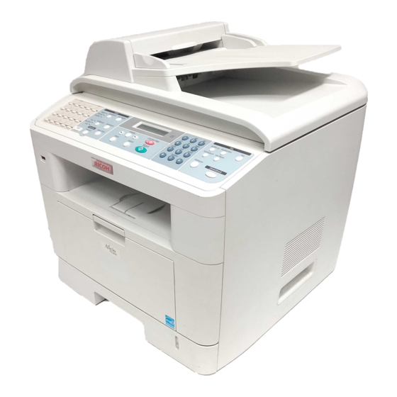
Summary of Contents for Ricoh AC205
-
Page 1: Service Manual
B273 SERVICE MANUAL 002544MIU... - Page 5 B273 SERVICE MANUAL 002544MIU...
- Page 7 It is the reader's responsibility when discussing the information contained within this document to maintain a level of confidentiality that is in the best interest of Ricoh Corporation and its member companies. NO PART OF THIS DOCUMENT MAY BE REPRODUCED IN ANY FASHION AND DISTRIBUTED WITHOUT THE PRIOR PERMISSION OF RICOH CORPORATION.
- Page 9 Ricoh Corporation. Users of this manual should be either service trained or certified by successfully completing a Ricoh Technical Training Program. Untrained uncertified users utilizing...
- Page 11 LEGEND PRODUCT CODE COMPANY GESTETNER LANIER RICOH SAVIN B273 DSm520pf AC122 AC205 AC205 DOCUMENTATION HISTORY REV. NO. DATE COMMENTS 09/2005 Original Printing...
-
Page 13: Table Of Contents
B273 TABLE OF CONTENTS INSTALLATION 1. INSTALLATION................1-1 PREVENTIVE MAINTENANCE 2. PREVENTIVE MAINTENANCE............ 2-1 2.1 PM INTERVALS ..................2-1 REPLACEMENT AND ADJUSTMENT 3. REPLACEMENT AND ADJUSTMENT ........3-1 3.1 GENERAL PRECAUTIONS...............3-1 3.1.1 SERVICING THE MACHINE ............3-1 3.1.2 RELEASING PLASTIC LATCHES............3-1 3.2 COVERS ....................3-2 3.2.1 REAR COVER ..................3-2 3.2.2 SIDE COVERS .................3-3 Right Cover...................3-3... - Page 14 3.13 CRUM BOARD ..................3-37 3.14 DRIVE ASSEMBLY ................3-38 3.15 COVER MID-FRONT................3-39 3.16 TRANSFER ASSEMBLY ...............3-40 3.17 FEED ASSEMBLY.................3-42 3.18 PICK-UP ASSEMBLY AND SOLENOID..........3-45 3.18.1 PICK-UP ASSEMBLY..............3-45 3.18.2 SOLENOID ...................3-46 3.18.3 BY-PASS PICK-UP ROLLER AND PAPER FEED UNIT PICK-UP ROLLER..............3-47 By-pass pick-up roller .................3-47 Paper Feed Unit Pick-up Roller ............3-48 TROUBLESHOOTING...
- Page 15 4.4.6 COVER OPEN 1................4-17 4.4.7 COVER OPEN 2................4-18 4.4.8 DEFECTIVE MOTOR OPERATION ..........4-18 4.4.9 NO POWER..................4-18 4.4.10 PRINTED VERTICAL LINES ARE CURVED........4-19 4.5 PRINTING QUALITY PROBLEMS ............4-20 4.5.1 INCORRECT PRINT POSITION ............4-20 4.5.2 VERTICAL WHITE LINE..............4-20 4.5.3 HORIZONTAL BLACK BANDS ............4-21 4.5.4 BLACK/WHITE SPOTS ..............4-21 4.5.5 LIGHT IMAGE ................4-22 4.5.6 DARK/BLACK IMAGE ..............4-22...
- Page 16 4.11.3 ABNORMAL PRINTING ...............4-45 4.11.4 SPOOL ERROR ................4-45 How to Delete Data in the Spool Manager..........4-45 4.12 NETWORK PROBLEMS ...............4-46 4.12.1 GENERAL PROBLEMS..............4-46 4.12.2 WINDOWS PROBLEMS...............4-47 4.12.3 SYNCTHRU INSTALLATION PROBLEMS ........4-48 SERVICE PROGRAM MODE 5. SERVICE PROGRAM MODE............5-1 5.1 TECH MODE .....................5-1 5.1.1 HOW TO ENTER TECH AND EXIT MODE........5-1 What you can do in Tech Mode ............5-1 5.1.2 DATA SET-UP ..................5-2...
- Page 17 DETAILED DESCRIPTIONS 6. DETAILED DESCRIPTIONS ............6-1 6.1 PRINTER COMPONENT LAYOUT ............6-1 6.1.1 FRONT VIEW ...................6-1 6.1.2 REAR VIEW ..................6-2 6.2 SYSTEM LAYOUT ..................6-3 6.2.1 PAPER FEED ...................6-3 6.2.2 TRANSFER ASSEMBLY ..............6-3 6.2.3 DRIVE ASSEMBLY ................6-3 6.2.4 FUSING ASSEMBLY................6-4 Thermostat....................6-4 Thermistor.....................6-4 Hot Roller....................6-4 Pressure Roller ..................6-4...
- Page 18 1. AC Input....................6-14 2. Rated Output Power .................6-14 3. Power Consumption .................6-14 4. Length of Power cord................6-15 5. Power Switch:...................6-15 6. Feature .....................6-15 7. Environment Condition ..............6-15 8. EMI Requirement................6-15 9. Safety Requirement ................6-15 6.4.3 FUSING UNIT AC POWER CONTROL..........6-16 6.5 ENGINE....................6-17 6.5.1 PAPER FEED .................6-17 Jam0 (feed area).................6-17...
-
Page 19: Safety Warning
PRECAUTIONS In order to prevent accidents and damage to the equipment, please read the following precautions before you service the machine. SAFETY WARNING 1. Only qualified service engineers should service this machine. High voltages and lasers inside this product should be approached with caution. 2. -
Page 20: Safety Precautions
SAFETY PRECAUTIONS TOXIC MATERIALS This product contains toxic materials that could cause illness if ingested. 1. If the LCD control panel is damaged, it is possible for the liquid inside to leak out. This liquid is toxic and contact with skin should be avoided. Wash any splashes from eyes or skin immediately for 15 minutes under running water, and contact a doctor. -
Page 21: Handling Precautions
9. Ensure that the power sockets and plugs are not cracked or broken in any way. Repair such defects immediately. Take care not to cut or damage the power cable or plugs when moving the machine. 10. Use caution during thunder or lightening storms. Disconnect the machine from the power source when such weather conditions are expected. - Page 22 ASSEMBLY/DISASSEMBLY PRECAUTIONS Replace with approved replacement parts only. Take care to note the exact location of components and correct cable routing before you disassemble any part of the machine. Ensure all parts and cables are replaced correctly. Perform the following procedures before you disassemble the machine or replace any parts: 1.
-
Page 23: Esd Precautions
ESD PRECAUTIONS Certain semiconductor devices can be easily damaged by static electricity. Such components are commonly called “Electro-statically Sensitive (ES) Devices”, or ESDs. Examples of typical ESDs are: integrated circuits, some field-effect transistors, and semiconductor “chip” components. The techniques outlined below should be followed to help reduce the incidence of component damage caused by static electricity. -
Page 25: Installation
INSTALLATION PREVENTIVE MAINTENANCE REPLACEMENT AND ADJUSTMENT TROUBLESHOOTING SERVICE PROGRAM MODE DETAILED DESCRIPTIONS SPECIFICATIONS APPENDIX... -
Page 27: Installation
INSTALLATION... - Page 29 INSTALLATION 1. INSTALLATION Refer to the Operating Instructions for Installation procedures. B273...
-
Page 31: Preventive Maintenance
PREVENTIVE MAINTENANCE... -
Page 33: Pm Intervals
PM INTERVALS 2. PREVENTIVE MAINTENANCE 2.1 PM INTERVALS The intervals shown below are for maintenance. Environmental conditions and machine use will affect these intervals. Adjust maintenance activities accordingly. NOTE: The intervals shown below are for reference only. It is expected that the intervals indicated below will exceed machine life. -
Page 35: Replacement And Adjustment
REPLACEMENT AND ADJUSTMENT... -
Page 37: General Precautions
GENERAL PRECAUTIONS 3. REPLACEMENT AND ADJUSTMENT This manual uses the following symbols : Screw : Connector : See or refer to 3.1 GENERAL PRECAUTIONS • Use caution when disassembling and reassembling components. • Ensure that all cables are correctly routed. Verify the correct cable routing before you begin service on the machine. -
Page 38: Covers
COVERS 3.2 COVERS 3.2.1 REAR COVER B273R903.WMF B273R902.WMF 1. Remove 4 x securing the rear cover [A]. Remove the rear cover from the frame assembly. B273R904.WMF 2. Unhook the face cover [B] from the rear cover as shown above. Lift the face cover out. -
Page 39: Side Covers
COVERS 3.2.2 SIDE COVERS Remove the following before removing the side covers: Rear cover 3.2.1 NOTE: Remove the paper tray unit before removing the side covers. Right Cover B273R905.WMF 1. Open the front cover and remove 2 x on the front, and 1 x on the back. 2. -
Page 40: Left Cover
COVERS Left Cover B273R906.WMF 1. Release 3 x clips [A] underneath the cover. 2. Ease the rear screw bracket over its location pin and gently slide the left cover [B] to the right. 3. Remove the left cover from the frame. B273... -
Page 41: Front Cover
COVERS 3.2.3 FRONT COVER B273R908.WMF B273R907.WMF 1. Open the front cover [A] and remove the toner cartridge [B]. B273R909.WMF 2. Unhook the front cover [A] from the frame assembly. Remove the front cover as shown above. B273... -
Page 42: Scanner Assembly
SCANNER ASSEMBLY 3.3 SCANNER ASSEMBLY Remove the following before removing the ADF motor assembly: Rear cover 3.2.1 Side covers 3.2.2 1. Remove 2 x from the scanner assembly, as shown. B273R910.WMF 2. Remove 5 x [A], as shown. 3. - Page 43 SCANNER ASSEMBLY B273R912.WMF 4. Lift up the scanner assembly, as shown above. 5. Lift and remove the platen cover [D], as shown. B273R913.WMF B273...
- Page 44 SCANNER ASSEMBLY B273R914.WMF 6. Free the scanner cable harness [E] from the clips [F] underneath the scanner. Remove it from the frame. B273R915.WMF 7. Lift the front part of the OPE front cover [G] to release it from the hooks connecting it to the scanning assembly.
- Page 45 SCANNER ASSEMBLY B273R916.WMF 8. Release the 3 x clips [H] on the front of the OPE unit [I]. Then remove the OPE as shown. NOTE: Ensure that the harness is threaded through the frame. B273R917.WMF 9. Remove 4 x securing the upper part [J] of the scanning unit. 10.
- Page 46 SCANNER ASSEMBLY B273R918.WMF 11. Remove the CCD cable [K], as shown above. B273R919.WMF 12. Pull up the CCD shaft [L] and remove the scanner module [M]. B273 3-10...
- Page 47 SCANNER ASSEMBLY B273R920.WMF 13. Squeeze the spring [N] to relieve tension on the belt [O]. Lift the belt away from the pulleys as shown. B273R921.WMF 14. Remove the reduction gear [P] and idle gear [Q], as shown. 15. Remove 3 x and remove the motor bracket [R]. 3-11 B273...
- Page 48 SCANNER ASSEMBLY B273R922.WMF 16. Unplug the connector from the open sensor assembly [S]. O pen Sensor B273R980.WMF 17. Unlatch the cover open sensor [T] and remove it. B273 3-12...
- Page 49 SCANNER ASSEMBLY Lock Unlock B273R923.WMF 18. Remove the CCD lock [U]. 3-13 B273...
-
Page 50: Reassembling The Scanner Assembly
SCANNER ASSEMBLY 3.3.1 REASSEMBLING THE SCANNER ASSEMBLY B273R924.WMF Ensure that the tension spring [A] is as close to the right-hand side of the scanner assembly as possible when reassembling the scanner module, belt, and belt spring. B273 3-14... -
Page 51: Adf Motor Assembly
ADF MOTOR ASSEMBLY 3.4 ADF MOTOR ASSEMBLY Remove the following before removing the ADF motor assembly: Rear cover 3.2.1 Side covers .3.2.2 Scanner assembly 3.3 B273R925.WMF 1. Unclip the harness [A] from the platen cover. 2. Remove the 2 x securing the ADF assembly and remove it. (Ensure that the harness is threaded through the frames). - Page 52 ADF MOTOR ASSEMBLY B273R927.WMF 4. Release the bushing [D] and rotate it until it reaches the slot, as shown above. 5. Remove the pick-up assembly [E]. B273R928.WMF 6. Remove the 2 x securing the upper cover [F] and remove the upper cover, as shown above.
- Page 53 ADF MOTOR ASSEMBLY B273R929.WMF 7. Unplug 1 x and 5 x securing the ADF assembly. 8. Remove the ADF motor assembly [H] from the ADF lower assembly [I]. NOTE: It is not necessary to disassemble the ADF unit if replacing only the separator pad.
-
Page 54: Operation Panel
OPERATION PANEL 3.5 OPERATION PANEL Remove the following before removing the operation panel: Rear cover 3.2.1 Side covers 3.2.2 Scanner assembly 3.3 B273R931.WMF B273R930.WMF 1. Remove 10 x securing the operation board panel cover [A] from the operation board panel assembly [B]. 2. - Page 55 OPERATION PANEL B273R932.WMF 3. Remove the keypad [D] from the operation panel board cover. 3-19 B273...
-
Page 56: Middle Cover And Exit Roller
MIDDLE COVER AND EXIT ROLLER 3.6 MIDDLE COVER AND EXIT ROLLER Remove the following before removing the middle cover and exit roller: Rear cover 3.2.1 Side covers 3.2.2 Scanner assembly 3.3 B273R933.WMF 1. Remove 4 x securing the middle cover [A]. Remove the middle cover. B273R934.WMF 2. - Page 57 MIDDLE COVER AND EXIT ROLLER B273R935.WMF 5. Remove the exit gear [C], exit roller [D], and 4 x bushings [E], as shown above. 3-21 B273...
-
Page 58: Controller Shield Assembly
CONTROLLER SHIELD ASSEMBLY 3.7 CONTROLLER SHIELD ASSEMBLY Remove the following before removing the control shield assembly: Rear cover 3.2.1 Side covers 3.2.2 B273R936.WMF 1. Remove all connectors and 5 x securing the controller shield assembly [A] to the middle cover and the frame. Remove the assembly. 2. - Page 59 CONTROLLER SHIELD ASSEMBLY B273R938.WMF 4. Remove the 5 x to remove the bracket [C] from the main board [D]. 3-23 B273...
-
Page 60: Engine Shield Assembly And Exit Board
ENGINE SHIELD ASSEMBLY AND EXIT BOARD 3.8 ENGINE SHIELD ASSEMBLY AND EXIT BOARD Remove the following before removing the engine shield and exit board: Rear cover 3.2.1 Side covers 3.2.2 Scanner assembly 3.3 3.8.1 ENGINE SHIELD B273R939.WMF 1. Unplug the following connectors: [A] Exit connector [B] Main connector [C] AC connector... - Page 61 ENGINE SHIELD ASSEMBLY AND EXIT BOARD B273R940.WMF 2. Remove the 11 x securing the engine shield assembly [A]. Tilt the assembly to one side. Unplug all harnesses before removing the assembly. 3-25 B273...
-
Page 62: Exit Board
ENGINE SHIELD ASSEMBLY AND EXIT BOARD 3.8.2 EXIT BOARD B273R941.WMF 1. Remove the 2 x exit board [B] 2. Remove the board. B273 3-26... -
Page 63: Smps And Liu
SMPS AND LIU 3.9 SMPS AND LIU Remove the following before removing the SMPS and LIU: Rear cover 3.2.1 Side covers 3.2.2 Scanner assembly 3.3 Engine shield assembly 3.8 B273R942.WMF 1. Remove the 2 x securing the inlet bracket [A] and remove the bracket. 2. - Page 64 SMPS AND LIU B273R944.WMF 3. Remove the 3 x securing the SMPS [C]. Lift the SMPS out as shown above. 4. Remove the 3 x securing the LIU. Lift the LIU [D] out, as shown in the illustration on the right.
-
Page 65: Fusing Unit
FUSING UNIT 3.10 FUSING UNIT Remove the following before removing the fusing unit: Rear cover 3.2.1 3.10.1 FUSING UNIT ASSEMBLY NOTE: Perform procedure 3.10.1 only if removal of entire fusing unit assembly is required. Otherwise, use individual component procedures. B273R946.WMF 1. -
Page 66: Thermostat
FUSING UNIT 3.10.2 THERMOSTAT B273R947.WMF 1. Remove the 4 x (bolts) [A] securing the thermostat [B]. 2. Lift the thermostat [B] out. Ensure that bolts and nuts [C] are stored in a safe place. 3.10.3 FUSING LAMP B273R948.WMF 1. Remove the 2 x securing the fusing lamp [A]. 2. -
Page 67: Stripper Pawls
FUSING UNIT 3.10.4 STRIPPER PAWLS B273R949.WMF 1. Remove the 4 x securing the fusing unit cover [A]. 2. Remove the 2 x securing the guide input [B]. 3. Remove the stripper pawls [C] from the fusing unit cover [A]. 3-31 B273... -
Page 68: Reassembling The Fusing Unit
FUSING UNIT Reassembling the Fusing Unit The four stripper pawls must be placed in the correct position before reassembling the fusing unit. Perform the following procedure before placing the fusing unit back into the fusing unit assembly. 1. Snap the four stripper pawls [A] out of the left and right side stripper pawl holder slots (shown in white circles below). -
Page 69: Note
FUSING UNIT Note: The illustration below shows the stripper pawls in the incorrect position. Note that the stripper pawls are not correctly set into the stripper pawl holder slots. Do not place the fusing unit back into the machine with the stripper pawls in the wrong position. -
Page 70: Thermistor
FUSING UNIT 3.10.5 THERMISTOR B273R950.WMF 1. Unwrap the thermistor harness [A], as shown above. B273R951.WMF 2. Remove 1 x securing the thermistor [B] and remove the thermistor. B273 3-34... -
Page 71: Fan
3.11 FAN Remove the following before removing the fan: Rear cover 3.2.1 Side covers 3.2.2 B273R952.WMF 1. Unplug the 1 x [A] from the SMPS. 2. Remove the 1 x securing fan [B]. 3. Remove the fan [B]. 3-35 B273... -
Page 72: Lsu
3.12 LSU Remove the following before removing the LSU: Rear cover 3.2.1 Side covers 3.2.2 Scanner assembly 3.3 Front cover 3.2.3 Middle cover 3.6 B273R953.WMF 1. Remove the 4 x securing the LSU [A] and remove the LSU. 2. Ensure that the wire [B] is kept in a safe place. 3. -
Page 73: Crum Board
CRUM BOARD 3.13 CRUM BOARD Remove the following before removing the CRUM board: Rear cover 3.2.1 Side covers 3.2.2 Scanner assembly 3.3 Front cover 3.2.3 Middle cover 3.6 LSU 3.12 B273R956.WMF 1. Remove the 4 x to separate the CRUM board [A] from the mainframe, as shown above. -
Page 74: Drive Assembly
DRIVE ASSEMBLY 3.14 DRIVE ASSEMBLY Remove the following before removing the drive assembly: Rear cover 3.2.1 Side covers 3.2.2 Controller shield assembly 3.7 B273R955.WMF 1. Remove the 5 x securing the drive assembly. 2. Remove the drive assembly [B]. 3. -
Page 75: Cover Mid-Front
COVER MID-FRONT 3.15 COVER MID-FRONT Remove the following before removing cover mid-front: Rear cover 3.2.1 Side covers 3.2.2 Middle cover 3.6 B273R958.WMF 1. Remove the 4 x securing the cover mid-front [A]. 2. Release the 2 clips [B] in the center. 3. -
Page 76: Transfer Assembly
TRANSFER ASSEMBLY 3.16 TRANSFER ASSEMBLY Remove the following before removing the transfer assembly: Rear cover 3.2.1 Side covers 3.2.2 Scanner assembly 3.3 Front cover 3.2.3 Middle cover 3.6 LSU 3.12 Cover Mid-Front 3.15 B273R959.WMF 1. Remove the 3 x securing the transfer ground [A] and remove the ground. B273R960.WMF 2. - Page 77 TRANSFER ASSEMBLY B273R961.WMF 4. Remove the transfer roller [E] by pressing the hook [F] securing the roller to the right. B273R962.WMF 5. Unlatch the bushing [G] and remove it. 6. Lift the transfer roller [H] out, as shown above. 3-41 B273...
-
Page 78: Feed Assembly
FEED ASSEMBLY 3.17 FEED ASSEMBLY Remove the following before removing the feed assembly: Rear cover 3.2.1 Side covers 3.2.2 Scanner assembly 3.3 Front cover 3.2.3 Middle cover 3.6 Controller shield assembly 3.7 Drive assembly 3.14 B273R963.WMF 1. Remove the 4 x securing the guide paper front, and remove the guide paper. 2. - Page 79 FEED ASSEMBLY B273R965.WMF 4. Remove the 3 x securing the feed bracket [C], and remove the bracket. B273R967.WMF 5. Remove feed gear 2 [D]. 3-43 B273...
- Page 80 FEED ASSEMBLY B273R966.WMF 6. Remove feed gear 1 [E]. B273R968.WMF 7. Remove the feed roller [F]. 8. Remove feed roller 1 [G], as shown above. B273 3-44...
-
Page 81: Pick-Up Assembly And Solenoid
PICK-UP ASSEMBLY AND SOLENOID 3.18 PICK-UP ASSEMBLY AND SOLENOID Remove the following before removing the pick-up assembly and solenoid: Rear cover 3.2.1 Side covers 3.2.2 Scanner assembly 3.3 Front cover 3.2.3 Middle cover 3.6 Controller shield assembly 3.7 Drive assembly 3.14 Engine shield assembly 3.8 Feed assembly 3.17 3.18.1 PICK-UP ASSEMBLY... -
Page 82: Solenoid
PICK-UP ASSEMBLY AND SOLENOID 3.18.2 SOLENOID B273R971.WMF 3. Remove the 1 x securing the pick-up solenoid [C] and remove the solenoid. 4. Remove the 1 x securing the manual solenoid [D] and remove the solenoid. B273R972.WMF 5. To replace the pick-up roller, move the stopper [E] securing the sponge roller [F] top the right. -
Page 83: By-Pass Pick-Up Roller And Paper Feed Unit Pick-Up Roller
PICK-UP ASSEMBLY AND SOLENOID 3.18.3 BY-PASS PICK-UP ROLLER AND PAPER FEED UNIT PICK- UP ROLLER It is possible to replace the by-pass or paper feed unit pick-up rollers only. Perform the following procedures only if it is necessary to replace the by-pass pick-up roller or the paper feed unit pick-up roller. -
Page 84: Paper Feed Unit Pick-Up Roller
PICK-UP ASSEMBLY AND SOLENOID Paper Feed Unit Pick-up Roller B273R974.WMF 1. Turn the machine upside down. 2. Release the white catch [C]. Slide the locking piece as far to the side as possible. 3. Slide the white collar [D] as far to the side as possible. 4. -
Page 85: Troubleshooting
TROUBLESHOOTING... -
Page 87: Paper Path
PAPER PATH 4. TROUBLESHOOTING 4.1 PAPER PATH The diagram below shows the paper path for the scanner and the engine of the machine. Refer to the next two pages for more details. (30She ets) Engine Part L S U Fuser Toner Cartridge B273T04.WMF [A] Scanner... -
Page 88: Copy/Scan Document Path
PAPER PATH 4.1.1 COPY/SCAN DOCUMENT PATH Scanner White-Sheet B273T05.WMF 1. Paper 5. Registration sensor 2. Pick-up roller 6. Scanning sensor 3. ADF roller 7. Feed roller 4. Document sensor 8. Exit roller B273... -
Page 89: Engine
PAPER PATH Engine Engine Part L S U B273T06.WMF 1. Paper feed unit 5. Paper empty sensor (paper feed unit) 2. By-pass tray 6. Paper feed sensor 3. Paper output area (face down) 7. Paper exit sensor 4. Paper empty sensor (by-pass) B273... -
Page 90: Printer Paper Path
PAPER PATH 4.1.2 PRINTER PAPER PATH The machine feeds paper from the main cassette or by-pass tray when it receives a print command. The paper being fed passes the paper feed sensor. 1. Jam 0 occurs if the sensor is not actuated within a certain time. 2. -
Page 91: Paper Jam Conditions
PAPER JAM CONDITIONS 4.2 PAPER JAM CONDITIONS The following are conditions in which paper can become jammed during a print job: • The tray is loaded incorrectly or overfilled. • The tray has been pulled out during a print job. •... -
Page 92: Clearing Document Jams (Adf)
PAPER JAM CONDITIONS 4.2.1 CLEARING DOCUMENT JAMS (ADF) “DOCUMENT JAM” appears on the operation panel if a document jams when fed through the ADF. ADF Input Misfeed Perform the following to remove a jam of this type: 1. Open the top cover [A]. B273T11.WMF B273T12.WMF 2. -
Page 93: Adf Exit Misfeed
PAPER JAM CONDITIONS ADF Exit Misfeed Perform the following to remove a jam of this type: 1. Open the document cover and turn the release knob to remove the misfed documents from the exit area. 2. Close the document cover. Load the documents to the ADF again. ADF Roller Misfeed Perform the following to remove a jam of this type: 1. -
Page 94: Jam0 (Paper Feed Area)
PAPER JAM CONDITIONS 4.2.2 JAM0 (PAPER FEED AREA) Perform the following to remove a jam of this type: 1. Open and close the front cover. The jammed paper should automatically exit the machine. (Proceed to the next step if the paper does not exit.) 2. -
Page 95: Jam1 (Fusing Area Or Around The Toner Cartridge Area)
PAPER JAM CONDITIONS 4.2.3 JAM1 (FUSING AREA OR AROUND THE TONER CARTRIDGE AREA) Perform the following to remove a jam of this type: NOTE: The fusing area is hot. Use caution when removing paper from this area of the machine. 1. -
Page 96: Jam2 (Paper Exit Area)
PAPER JAM CONDITIONS 4.2.4 JAM2 (PAPER EXIT AREA) Perform the following to remove a jam of this type: 1. Open and close the front cover. The jammed paper automatically exits the machine. Proceed to step two if the paper does not exit from the machine. 2. -
Page 97: By-Pass Tray Jam
PAPER JAM CONDITIONS 4.2.5 BY-PASS TRAY JAM “MP Tray Jam” appears on the display when printing via the by-pass tray, and the machine does not detect paper. This occurs due to no paper, or improper paper loading. This error message may also occur when the paper is not properly fed into the machine through the manual feeder. -
Page 98: Paper Feed Problems
PAPER FEED PROBLEMS 4.3 PAPER FEED PROBLEMS 4.3.1 INCORRECT PRINT POSITION Description: The print job begins despite the paper being in the incorrect position in the paper cassette. Cause Solution Defective feed sensor actuator Replace the defective actuator 4.3.2 JAM 0 Description: •... -
Page 99: Jam 1
PAPER FEED PROBLEMS 4.3.3 JAM 1 Description: • Paper becomes jammed in front of, or inside, the fusing unit. • Paper becomes stuck in the discharge EXIT Sensor M P S e n s o r F e e d S e n s o r roller and in the fusing unit, after it passes through the actuator feed. -
Page 100: Multi-Feeding
PAPER FEED PROBLEMS 4.3.5 MULTI-FEEDING Description: Multiple sheets of paper are fed at the same time. EXIT Sensor M P S e n s o r F e e d S e n s o r B273T10.WMF Cause Solution Paper size guides may not be set Adjust the paper guides. -
Page 101: Paper Becomes Rolled Around The Opc Drum
PAPER FEED PROBLEMS 4.3.7 PAPER BECOMES ROLLED AROUND THE OPC DRUM Description: Paper becomes rolled around the OPC drum. Cause Solution Paper is too thin. Use paper supported for use in this machine. (See Operator Guide) The face of the paper is curled. Ensure that paper is stored correctly. -
Page 102: Machine Malfunctions
MACHINE MALFUNCTIONS 4.4 MACHINE MALFUNCTIONS 4.4.1 LCD DISPLAY DEFECTIVE Description: Unusual characters appear on the LCD panel, or the operation panel buttons do not work. Cause Solution The memory needs to be cleared. Clear the memory and attempt to use the machine again. -
Page 103: Paper Empty 1
MACHINE MALFUNCTIONS 4.4.4 PAPER EMPTY 1 Description: “Paper Empty” appears on the LCD when paper is loaded in the cassette. Cause Solution Paper sensor or paper sensor actuator is Replace the defective sensor or actuator. damaged. Replace the SMPS or main board. SMPS or main PBA is defective. -
Page 104: Cover Open 2
MACHINE MALFUNCTIONS 4.4.7 COVER OPEN 2 Description: “Cover Open” message does not appear on the LCD when the front cover is open. Cause Solution “Open Cover” microswitch is stuck or Perform the cover sensor test in Tech damaged. Mode to check cover switch operation. Replace the switch if necessary. - Page 105 MACHINE MALFUNCTIONS 4.4.10 PRINTED VERTICAL LINES BEND Description: Vertical lines are curved on output prints. Cause Solution 24 V power supply to the LSU is faulty. Replace the LSU if the 24 V power supply is stable. Replace the SMPS if the 24 V power supply is unstable.
-
Page 106: Printing Quality Problems
PRINTING QUALITY PROBLEMS 4.5 PRINTING QUALITY PROBLEMS 4.5.1 INCORRECT PRINT POSITION Description: Paper is fed despite the paper being in the incorrect position in the paper cassette. Cause Solution Defective feed sensor actuator Replace the defective actuator 4.5.2 VERTICAL WHITE LINE Description. -
Page 107: Horizontal Black Bands
PRINTING QUALITY PROBLEMS 4.5.3 HORIZONTAL BLACK BANDS Description: Dark or blurry horizontal stripes appear Digital Printer periodically on the output print. Digital Printer Digital Printer Digital Printer Digital Printer B273T915.WMF Cause Solution Bad contacts on the toner cartridge high- Clean all high-voltage terminals on the voltage terminals. -
Page 108: Light Image
PRINTING QUALITY PROBLEMS 4.5.5 LIGHT IMAGE Description: Printed image is too light (no “ghosting”). Digital Printer Digital Printer Digital Printer Digital Printer Digital Printer B273T917.WMF Cause Solution Toner save mode is enabled. Turn the toner save more off. Developer roller is contaminated or the Replace the toner cartridge. -
Page 109: Uneven Density
PRINTING QUALITY PROBLEMS 4.5.7 UNEVEN DENSITY Description: Print density is uneven between the left and right sides of the output print. B273T920.WMF Cause Solution Pressure force on the left and right Replace both the left and right bushings springs of the transfer roller is not even, and spring assemblies. -
Page 110: Ghost 1
PRINTING QUALITY PROBLEMS 4.5.9 GHOST 1 Description: Image “Ghosting” appears on the output prints at Digital Printer 75.5 mm intervals. Digital Printer Digital Printer Digital Printer Digital Printer Digital Printer B273T922.WMF Cause Solution Bad contacts caused by toner particles Clean all HV contacts. Replace the HVPS between the high voltage terminal in the if the problem persists. -
Page 111: Ghost 3
PRINTING QUALITY PROBLEMS 4.5.11 GHOST 3 Description: Image “Ghosting” appears on the output print at Digital Printer Digital Printer 66.3 or 75.5 mm intervals. Digital Printer Digital Printer Digital Printer Digital Printer B273T924.WMF Cause Solution Fusing unit is contaminated Disassemble the fusing unit and remove matter from the rollers. -
Page 112: Marks On Front Of Page
PRINTING QUALITY PROBLEMS 4.5.13 MARKS ON FRONT OF PAGE Description: Background or black marks are visible on the Digital Printer output print. Digital Printer Digital Printer Digital Printer Digital Printer B273T926.WMF Cause Solution Toner leakage due to incorrectly sealed Replace the toner cartridge. toner cartridge. -
Page 113: Blank
PRINTING QUALITY PROBLEMS 4.5.15 BLANK PAGE 1 Description: Blank page is printed. Digital Printer Digital Printer Digital Printer Digital Printer Digital Printer B273T928.WMF Cause Solution Bad ground contacts in the OPC and/or toner Check if the ground OPC or the OPC ground cartridge. -
Page 114: Fax And Phone Problems
FAX AND PHONE PROBLEMS 4.6 FAX AND PHONE PROBLEMS 4.6.1 NO DIAL TONE Description: No dial tone when the “On-Hook Dial” (OHD) button is pressed. Cause Solution Telephone line cord is not securely Test the wall socket by plugging in a connected to the TEL LINE. -
Page 115: Defective Fax Forward/Receive
FAX AND PHONE PROBLEMS 4.6.3 DEFECTIVE FAX FORWARD/RECEIVE Description: Fax Forward/Receive function does not function correctly. Cause Solution No dial tone is heard when you press the Replace the LIU if the modem test is On Hook Dial (OHD) button. normal but there is still no dial tone. -
Page 116: Defective Fax Receive 2
FAX AND PHONE PROBLEMS 4.6.6 DEFECTIVE FAX RECEIVE 2 Description: Received data is lengthened or cut off in the printout. Cause Solution An unusual noise is heard when “On- Repair the telephone line. Hook” is pressed. Replace the LIU or main PBA in Use the same wall socket and ask the sequence. -
Page 117: Copy Problems
COPY PROBLEMS 4.7 COPY PROBLEMS 4.7.1 WHITE COPY Description: Blank page is printed out when copying. Cause Solution Scanner cover is not closed. Close the scanner cover. Shading profile is not correctly set. Perform the shading profile in Tech mode. Faulty white/black reference voltage on Replace the main PBA. -
Page 118: Scanning Problems
SCANNING PROBLEMS 4.8 SCANNING PROBLEMS 4.8.1 PC SCANNING PROBLEMS Description: Unable to scan via the PC. Cause Solution Cable (USB or Parallel) is not correctly Replace faulty cables. Ensure that the connected. parallel port is correctly configured in the BIOS. Drive is not correctly installed. -
Page 119: Error Messages
ERROR MESSAGES 4.9 ERROR MESSAGES Error Description Solution By-pass tray jam (door Paper is either jammed in the by- Clear the paper jam and open) pass tray, or paper is not fed load paper correctly. correctly. Cancel? 1. Yes, 2. No The memory becomes full when Press the ‘1’... - Page 120 ERROR MESSAGES Error Description Solution Memory full The memory is full. Delete unnecessary documents (delayed transmission, broadcast, polling etc.), or transmit the documents again when more memory becomes available. This can also occur when sending a large, multiple paged, complex document. In this condition, split the document into more than one job.
- Page 121 ERROR MESSAGES Error Description Solution Priority fax function full The priority fax job queue is full. Cancel unnecessary priority fax jobs. Incompatible The remote machine does not Reconfirm the features of the remote machine. have the requested feature, such as sending a color fax. This message can also show if the remote machine does not have enough memory to...
-
Page 122: Toner Cartridge
TONER CARTRIDGE 4.10 TONER CARTRIDGE Ensure that only toner cartridges approved by the manufacturer are used in this machine. Machine operation is not guaranteed if toner cartridges not approved by the manufacturer are used. 4.10.1 TONER CARTRIDGE PRECAUTIONS Do no expose the toner cartridge to direct light for more than a few seconds. Print quality can be temporarily improved by redistributing the toner, if the printed image is light due to low toner supply. -
Page 123: Redistributing Toner
TONER CARTRIDGE 4.10.2 REDISTRIBUTING TONER White streaks or light printouts appear when the toner cartridge is near end of life. At this time, the LCD displays shows the ‘Toner Low’ message. To temporarily bypass this problem, redistribute the remaining toner in the cartridge. B273T01.WMF 1. -
Page 124: Toner Cartridge Error Messages
TONER CARTRIDGE 4.10.3 TONER CARTRIDGE ERROR MESSAGES The following table shows toner cartridge-related error messages. The messages are generated via data stored in the EEPROM in the toner cartridge. Error Message Description Solution Toner Low The amount of remaining Replace the cartridge. toner is less than 10%. -
Page 125: Toner Cartride Details
TONER CARTRIDGE 4.10.4 TONER CARTRIDE DETAILS Description Signs Solution Light image/partially • Printed image is If the image is light, shake the toner blank image light, dirty, or not cartridge and try to print again. If the (cartridge has clear. problem persists, the cartridge has reached end of life) •... - Page 126 TONER CARTRIDGE Description Signs Cause and Check and Solution White/Black Spot • Light or dark black Toner cartridge rollers are contaminated dots are visible with particles, if light or dark black dots periodically on the appear periodically on the image. In this image.
- Page 127 TONER CARTRIDGE Description Signs Cause and Check and Solution Recycled Cartridge • Toner cartridge 1. The toner cartridge is recycled if the appears to be in following are true: poor condition. A) There is evidence that the toner • Dirty or rough cartridge has been disassembled.
- Page 128 TONER CARTRIDGE Description Signs Cause and Check and Solution Ghost image and • Print is too light or Check the following if the printout is too other contamination dark, or partially light, too dark or partially contaminated. contaminated. A) Check if matter remains on the •...
-
Page 129: Software Problems
SOFTWARE PROBLEMS 4.11 SOFTWARE PROBLEMS 4.11.1 PRINTER DOES NOT OPERATE CORRECTLY 1 Description: The printer does not operate in printing mode when the power is turned on. Description Solution Perform the self-test mode. Use the menu There are no problems with the machine, if buttons (menu, enter, enter) and print the test the test print works correctly. -
Page 130: Printer Does Not Operate Correctly 1
SOFTWARE PROBLEMS 4.11.2 PRINTER DOES NOT OPERATE CORRECTLY 2 Description: After receiving the print command there is either no response or the print speed is slower than normal. Incorrect machine set-up and printer malfunction are the causes of this condition. Description Solution Not enough free hard disk space to... -
Page 131: Abnormal Printing
Printer driver error Ensure that the correct driver is loaded. Use the driver supplied on the CD, or download the correct driver from the Ricoh web site. DO NOT use the Microsoft driver supplied with the Windows operating system. If the printer is a GDI or SPL type... -
Page 132: Network Problems
NETWORK PROBLEMS 4.12 NETWORK PROBLEMS 4.12.1 GENERAL PROBLEMS Description Solution Incorrect set-up can cause network Parameters in the PortThru (network card) may be errors. corrupt. Restart the printer and reset the printer network settings to the factory defaults with the front panel or with SyncThru on the PC. -
Page 133: Windows Problems
NETWORK PROBLEMS 4.12.2 WINDOWS PROBLEMS Description Solution Print server name does not show under new 1. Ensure that the power switch is print server in SyncThru after you install turned on and the ‘READY’ message PortThru. shows on the operation panel. 2. -
Page 134: Syncthru Installation Problems
NETWORK PROBLEMS Description Solution 6. Ensure that there is no router between the printer and the computer. SyncThru cannot work through a router. 7. Ensure that there are no switch or router VLAN or access control lists that block communication between the printer and the computer. -
Page 135: Service Program Mode
SERVICE PROGRAM MODE... -
Page 137: Tech Mode
TECH MODE 5. SERVICE PROGRAM MODE 5.1 TECH MODE Tech Mode allows for checking of the machine and various tests to resolve problems. The machine can still operate normally when Tech Mode. 5.1.1 HOW TO ENTER AND EXIT TECH MODE Perform the following to enter tech mode: B273S01 WMFMF The LED shows “Tech”... -
Page 138: Data Set-Up
TECH MODE 5.1.2 DATA SET-UP Send Level Send level sets the level of the transmission signal. The Tx level should normally be under -12 dBm. The send fax level is set to the best condition during manufacture. This should not be changed in the field. -
Page 139: Clear All Memory
TECH MODE CLEAR ALL MEMORY Use this function to reset the system to the default set at the factory. This function resets the system to the initial value when the machine does not function correctly. Values are set to the default values. The machine will not keep data set by the user. -
Page 140: Machine Tests
TECH MODE 5.1.3 MACHINE TESTS Switch Test Switch Test tests the keys on the operation panel. The result shows on the LCD window when a key is pressed. Modem Test Modem Test allows you to hear various transmission signals to the telephone line, from the modem and to check the modem, amplifier, and speaker. -
Page 141: Shading Test
TECH MODE Shading Test Shading Test sets the optimum scan quality determined by the specific characteristics of the CCD (Charge Coupled Device). Perform the following procedure to check the condition of the CCD unit if copy image quality is poor. Procedure 1) Select the [Shading Test] in tech mode (Menu, #, 1934). -
Page 142: User Mode
USER MODE 5.2 USER MODE The table below shows functions available to the user. Refer to the Operating Instructions for further details. Function Item Contents 1. Paper Setting Copy Tray Auto tray / MP tray Fax Tray Auto tray / MP tray Paper Size Tray Paper A4 / A5 / B5 / A6 / LTR /... - Page 143 Function Item Contents 7. Reports Phone Book Phone Book List Sent Report Transmission Journal RCV Report Reception Journal System Data System Data List Scheduled Jobs Schedule Information List MSG Confirm Message Confirmation Report Junk Fax List Junk Fax List Scan Journal 8.
-
Page 144: Firmware Download
FIRMWARE DOWNLOAD 5.3 FIRMWARE DOWNLOAD The “Printer Setting Utility” can be used by connecting the machine to a PC through a parallel or USB cable, or via Web Image Monitor through a network, to upgrade the machine firmware. 5.3.1 DOWNLOAD PROCEDURE NOTE: Do not turn off the machine power while updating the firmware. -
Page 145: Web Image Monitor Mode
FIRMWARE DOWNLOAD Web Image Monitor Mode 1. Print out the System Data list, as a precaution, to back up system data and settings. 2. Download the firmware onto the PC. NOTE: 1) Ensure that both the “Printer Firmware” and “Network Firmware” are downloaded, if both are to be updated. - Page 146 FIRMWARE DOWNLOAD 5. Ensure that “Printer Firmware” [A] is selected, as shown below. NOTE: Proceed to step 9 if only the “Network Firmware” is to be upgraded. B273S04.TIF 6. Click the “Browse” button, and select the printer firmware file saved on the PC. 7.
-
Page 147: Firmware Recovery Procedure
FIRMWARE DOWNLOAD 9. Ensure that “Network Firmware” [B] is selected, as shown below. B273S05.TIF 10. Click the “Browse” button and select the network firmware file saved on the PC. 11. Click the “Upgrade” button 12. Ensure that the firmware is completely updated. 5.3.2 FIRMWARE RECOVERY PROCEDURE The machine will not operate if the update procedure did not function correctly. -
Page 148: Engine Test Mode
ENGINE TEST MODE 5.4 ENGINE TEST MODE The Engine Test Mode checks the condition of the print engine. It tests the condition of each device, and shows the result of the test on the LCD. The Engine Test Mode is divided into 5 functions (0~4). 5.4.1 HOW TO ENTER ENGINE TEST MODE Perform this procedure to enter Engine Test Mode: Press Menu →... -
Page 149: Engine Test Mode Table
ENGINE TEST MODE 5.4.2 ENGINE TEST MODE TABLE Test Sub Number Engine test Remark Number Motor test 1: On, 2: Off. Next test selected Pick-up test 1: On, 2: Off. Next test selected Fan test 1: On, 2: Off. Next test selected Manual CLT test 1: On, 2: Off. -
Page 150: Detailed Description (Engine Test Mode)
ENGINE TEST MODE Detailed Description (Engine Test Mode) Function name Description Display 01. Motor test The motor starts when you press the Main motor on/off execution key is present, and stops when the stop key is pressed. 02. Pick-up test Automatically stops when execute is Tray 1, 2 solenoid on/off selected. -
Page 151: Status Print
ENGINE TEST MODE 5.4.3 STATUS PRINT When this function is enabled, a group of parameters are printed at the bottom of each page. These parameters show the print engine condition. Generally, this function is not necessary for service use. This setting remains on after exiting Engine Mode. Ensure that, if this function is used, it is set back to “off”... -
Page 153: Detailed Descriptions
DETAILED DESCRIPTIONS... -
Page 155: Printer Component Layout
PRINTER COMPONENT LAYOUT 6. DETAILED DESCRIPTIONS 6.1 PRINTER COMPONENT LAYOUT 6.1.1 FRONT VIEW B273D01.WMF [A] ADF [H] Paper level indicator [B] Document guides [I] Front door [C] Input tray [J] By-pass tray [D] Output tray [K] Standard paper tray unit [E] Operation panel [L] Paper output extension [M] USB flash drive port... -
Page 156: Rear View
PRINTER COMPONENT LAYOUT 6.1.2 REAR VIEW B273D02.WMF [A] Face-up door [F] Optional paper feed tray connector [B] Control board cover [G] External jack [C] Network port [H] Line jack [D] Parallel connector [I] AC power connector cord [E] USB connector [J] Power switch NOTE: The external jack may not be available for use if your country has a unique or different than the typical telephone system used by most countries. -
Page 157: System Layout
SYSTEM LAYOUT 6.2 SYSTEM LAYOUT 6.2.1 PAPER FEED The paper tray unit and the manual by-pass unit automatically feed paper to the machine. A friction pad separates the paper and ensures that paper is fed one sheet at a time. A sensor checks when the paper tray is empty. -
Page 158: Fusing Assembly
SYSTEM LAYOUT 6.2.4 FUSING ASSEMBLY The fusing unit consists of the following. • Fusing lamp • Hot roller • Pressure roller • Thermistor and thermostat The fusing unit uses pressure and heat to melt toner into the paper. Thermostat The thermostat cuts power to the fusing lamp to avoid machine overheat. Power is cut when the thermostat temperature reaches 160°... -
Page 159: Scanning Unit
SYSTEM LAYOUT 6.2.5 SCANNING UNIT The image is read using a photosensitive sensor. The scanning unit consists of the following: • CCD module • Connection board • ADF board • AFE (Analog Front End) • Image Processor (located in CPU) •... -
Page 160: Toner Cartridge
SYSTEM LAYOUT 6.2.7 TONER CARTRIDGE -430V -950V -580V B273D05.WMF [A] Charging roller [D] Doctor blade [B] OPC drum [E] Supply roller [C] Developing roller [F] Transfer roller The toner cartridge contains the OPC unit and toner unit. The OPC unit consists of the OPC drum and the charging roller. -
Page 161: New Aio Detection
SYSTEM LAYOUT 6.2.8 NEW AIO DETECTION Each AIO cartridge has an ID chip. The machine detects a new cartridge has been installed when the ID chip is detected. When a new cartridge is installed in the machine, the machine automatically detects, via the chip, that the cartridge is new. -
Page 162: Controller
CONTROLLER 6.3 CONTROLLER 6.3.1 MAIN PBA The Main PBA consists of the following components: Image Processor Motor Driver Line Transceiver Processor ASIC Motor Driver VEDIC X-TAL Flash Memory-Code CPU X-TAL High Flash Memory-Code CMOS-Logic Modem X-TAL Flash Memory-PCL6 CMOS-Logic USB host X-TAL High Flash Memory-PCL6 Panasonic... -
Page 163: Asic
CONTROLLER 6.3.2 ASIC A 32Bit RISC processor executes printer and fax functions. Main Function Block • Fully integrated system for embedded applications • LSU interface module, to interface with the PVC or HPVC • 2-channel, general-purpose DMA controller for high speed I/O •... -
Page 164: Sensor Input Circuit
CONTROLLER 6.3.7 SENSOR INPUT CIRCUIT Paper Empty Sensor The Paper Empty Sensor (photointerrupter) is monitored by the CPU signal “nP_EMPTY”. The machine shows a message on the LCD when the cassette is empty. By-pass Tray Sensor Paper in the By-pass Tray is detected by operation of the By-pass Sensor (photointerrupter). -
Page 165: Smps And Hvps
SMPS AND HVPS 6.4 SMPS AND HVPS The SMPS (Switching Mode Power Supply) and HVPS (High Voltage Power Supply) are located on the same board. The SMPS supplies either 110V or 220V DC power to the system, and outputs +5V, +12V and +24V supplies to the Main and other PBAs. -
Page 166: Hvps
SMPS AND HVPS 6.4.1 HVPS The HVPS supplies the following voltages to the machine: Transfer High Voltage (THV+): This voltage transfers toner from the OPC drum to the paper. • Output voltage: +1300V DC ±20V • Failure Symptom: Low-density printing occurs due to toner on the OPC drum that was not transferred to the paper due to THV (+) not present. -
Page 167: Supply Voltage (Sup)
SMPS AND HVPS Supply Voltage (SUP): This voltage supplies toner to the developing roller. • Output voltage: –580V DC ± 50V (Use ZENER, DEV Gear) • Failure Symptom: • Print density becomes extremely light when SUP is GND. • Print density becomes extremely light if SUP is “floating”, due to poor connection between the frame and cartridge contacts, etc. -
Page 168: Smps(Switching Mode Power Supply)
SMPS AND HVPS 6.4.2 SMPS(SWITCHING MODE POWER SUPPLY) SMPS is the power source for the entire system. It is mounted at the bottom of the machine and consists of the SMPS area, which supplies DC power to drive the system. SMPS also supplies power to the AC heater control area, which supplies the power to the fusing unit. -
Page 169: Length Of Power Cord
SMPS AND HVPS 4. Length of Power cord • 1830 ±50mm 5. Power Switch: • Fitted 6. Features • Insulation resistance : over 50M Ω(at DC500V) • Insulating retest pressure : No issues if within 1min. (at 1500Vzc, 10mA) • Leakage current : under 3.5mA •... -
Page 170: Fusing Unit Ac Power Control
SMPS AND HVPS 6.4.3 FUSING UNIT AC POWER CONTROL The fusing lamp is heated via AC power and is controlled by a triac (THY1). “On/Off control” is achieved when the gate of the triac is turned on/off by a phototriac (PC1). The phototriac also acts as an insulting component. The fusing heat lamp is turned on/off when it receives a signal from the Engine Control section. -
Page 171: Engine
ENGINE 6.5 ENGINE 6.5.1 PAPER FEED Jam0 (feed area) Jam0 occurs at the following times: • Paper does not enter the unit due to a paper misfeed after a page was picked up. • Paper entered, but did not reach the Feed Sensor in a specific time interval due to slip, etc. -
Page 172: Drive
ENGINE 6.5.2 DRIVE The Main Motor drives the following: • Paper feed unit • Developing unit • Fusing unit Software drives the Main Motor and controls the motor acceleration, motor speed, and motor de-celeration. The motor is managed via an A3977 driver IC and is con- trolled by signals from the CPU. -
Page 173: Laser Scanning Unit
OPERATION PANEL (OPE) 6.5.5 LASER SCANNING UNIT The LSU consists of the LD (Laser Diode) and the polygon motor control. When a printing signal is received, the LD is turned on and the polygon motor is enabled. When the light sensor detects the beam, HSync occurs. When the polygon motor speed reaches target, LReady occurs. -
Page 174: Usb Host
USB HOST 6.7 USB HOST The USB Host PBA provides power to the USB connector. This enables the USB memory drive to use the following functions: • Direct printing • Scan to USB functions 6.8 FAX SECTION 6.8.1 MODEM • Group 3 facsimile modem •... -
Page 175: Specifications
SPECIFICATIONS... -
Page 177: General Specifications
SPECIFICATIONS SPECIFICATIONS 1. GENERAL SPECIFICATIONS Configuration Desktop Paper capacity Main tray 250 sheets By-pass tray 50 sheets Optional paper 250 sheets feed unit Output tray Face down: 150 sheets Face up: 1 sheet Paper size Main tray A4, Letter, Legal, Folio, Executive, B5 By-pass tray Envelope 63/4, 73/4, #9, #10, DL, C5, B5 Paper weight... -
Page 178: Physical Specifications
SPECIFICATIONS 2. PHYSICAL SPECIFICATIONS Printing operation 370 W Energy saver Power consumption 30 W (energy start compliant) mode Power switch Supported Power supply Low voltage 110-127 V High voltage 220-240 V Input frequency 50/60 (± 3Hz) Noise Printing 54 dB Copy 55 dB Standby... -
Page 179: Scan Specifications
SPECIFICATIONS 4. SCAN SPECIFICATIONS Scan method Color CCD Scan speed Linearity Approximately 75 seconds (USB 1.1) through ADF Gray Approximately 75 seconds (USB 1.1) Color Approximately 150 seconds (USB 1.1) Scan speed Linearity Approximately 75 seconds (USB 1.1) through platen Gray Approximately 75 seconds (USB 1.1) Color... -
Page 180: Copy Specifications
SPECIFICATIONS 5. COPY SPECIFICATIONS Text 600 x 300 dpi Text/Photo 600 x 300 dpi Copy resolution Photo 600 x 600 dpi for platen Other Not supported First copy time From stanby 10 seconds: Platen 15 seconds: ADF From energy 50 seconds saver mode Copy speed (letter) SDMC (all... -
Page 181: Telephone Specifications
SPECIFICATIONS 6. TELEPHONE SPECIFICATIONS Handset On hook dial Supported Search Supported (phone book) 1 touch dial 40EA (20 x shift). 20 x 2 dedicated keys Speed dial 200 locations (00-199) Telephone answering Supported device I/F Tone/Pulse Supported (selected in Tech Mode) Pause Supported Auto redial... -
Page 182: Fax Specifications
SPECIFICATIONS 7. FAX SPECIFICATIONS Compatibility ITU-T, G3 Communication system PSTN/PABX Modem speed 33.6 Kbps Compression MH/MR/MMR/JPEG Color fax Supported (send only) Error correction mode Supported Resolution Standard 203 x 98 dpi Fine 203 x 196 dpi Super fine 300 x 300 dpi Scan speed Standard 2.5 seconds/LT... -
Page 183: Software Specifications
SPECIFICATIONS 8. SOFTWARE SPECIFICATIONS Windows 95/ME/NT 4.0/2000/XP Supported Mac: English only web version Operating sytems Windows 3.x/95 supported Linux WHQL MFP: Supported: Windows 2000/XP Printer PCL6 TWAIN Supported Drivers Supported Supported PC-Fax Supported (through PC modem and fax S/W) 9. PAPER SIZES/WEIGHTS Paper Tray Supported Paper Sizes Remarks... -
Page 185: Appendix
APPENDIX... -
Page 187: Block Diagram
BLOCK DIAGRAM APPENDIX BLOCK DIAGRAM B273X01.WMF B273... -
Page 188: Connection Diagram
CONNECTION DIAGRAM CONNECTION DIAGRAM B273X02.WMF B273...