Table of Contents

Related Manuals for THOMSON EAP 300

Summary of Contents for THOMSON EAP 300
-
Page 1: Installation Manual
EAP 300 REMOTE ANNUNCIATOR INSTALLATION MANUAL r.0454A PM084 Rev 0 08/06/20 9087A – 198 Street, Langley, BC Canada V1M 3B1 Telephone (604) 888-0110 Telefax (604) 888-3381 E-Mail: info@thomsontechnology.com www.thomsontechnology.com... -
Page 3: Table Of Contents
EAP 300 REMOTE ANNUNCIATOR CONTENTS WARNINGS AND LEGAL INFORMATION..................1 ....................1 EGAL INFORMATION AND RESPONSIBILITY ......................1 LECTROSTATIC DISCHARGE AWARENESS ...............................1 AFETY ISSUES ............................1 ACTORY SETTINGS ..............................1 EFINITIONS DESCRIPTION ............................2 REAR VIEW ..............................2 INSTRUCTIONS.............................3 FRONT VIEW ..............................3 INSTALLATION: ............................3 ................................4 IRING ............................5... -
Page 4: Warnings And Legal Information
Thomson Technology takes no responsibility for installation or operation of the engine set. If there is any doubt about how to install or operate the engine controlled by the unit, the company responsible for the installation or the operation of the set must be contacted. -
Page 5: Description
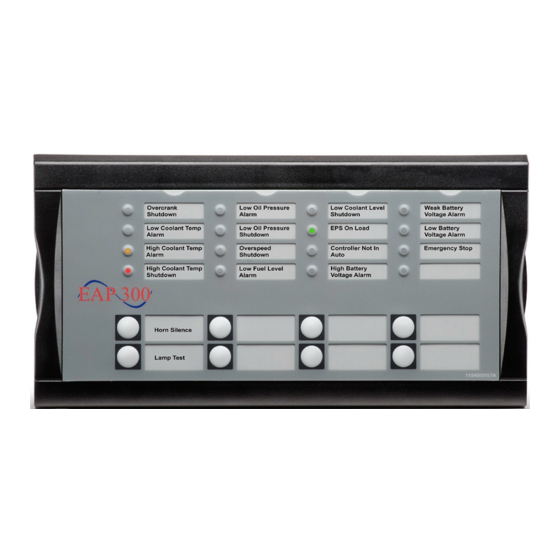
The EAP 300 has 16 configurable LEDs and 8 configurable buttons, which are programmed with the TPS 300 PC utility software. It can be used as an interface to the MEC 310 for indication of status and alarms together with buttons for e.g. remote alarm acknowledge and mode selection. -
Page 6: Instructions
The configurable LEDs are named 1 to 16. Buttons are named 1 to 8. INSTALLATION: Mount on a flat surface of a Type 1 Enclosure. Note the maximum ambient temperature rating is Panel Cut-out Detail: Dimensions in millimetres ( 1 inch = 25.4 mm ) -
Page 7: Wiring
MEC 310 is needed at all times. The default setting of the end resistor on the EAP 300 panel is ON. Thus, the dip switch is at the right position if only one EAP 300 is connected. If there are two EAP 300’s connected, the end resistor of the EAP 300 with a connector plug in both CAN 1 and CAN 2 must be switched off. -
Page 8: Error Handling
Duplicate CAN ID If two units on the CANbus have the same CAN ID, LED no. 1 to 4 will flash quickly. In this case press button no. 6 to jump into the CAN ID change menu and select another CAN ID for the unit.