Immergas MAGIS HERCULES PRO MINI 6 Instructions And Recommendations
Hide thumbs
Also See for MAGIS HERCULES PRO MINI 6:
- Instruction and warning book (8 pages) ,
- Instruction manual (12 pages)

Related Manuals for Immergas MAGIS HERCULES PRO MINI 6


Summary of Contents for Immergas MAGIS HERCULES PRO MINI 6
- Page 1 MAGIS Instructions and recommendations Installer HERCULES User Maintenance technician PRO MINI 6 - 9...
-
Page 2: Table Of Contents
INDEX Dear Customer ..........................................4 General Recommendations .....................................5 Safety symbols used ........................................6 Personal protective equipment ....................................6 Installing the indoor unit ................................7 Description of the product.....................................7 Installation warnings .....................................7 Indoor unit main dimensions ..................................10 Minimum indoor unit installation distances ............................11 Indoor unit hydraulic connection ................................12 Connecting the chiller line ..................................12 Electrical connection ....................................13... - Page 3 Technical data ..................................105 Technical data table ....................................105 4.2 Magis Hercules PRO MINI 6 product fiche (in compliance with Regulation 811/2013) ..............107 4.3 Table 2 Regulation 813/2013 ..................................108 Magis Hercules PRO MINI 9 product fiche (in compliance with Regulation 811/2013) ..............109 4.5 Table 2 Regulation 813/2013 ..................................110...
-
Page 4: Dear Customer
Dear Customer Congratulations for having chosen a top-quality Immergas product, able to assure well-being and safety for a long period of time. As an Im- mergas customer you can also count on a Qualified Authorised After-Sales Technical Assistance Centre, prepared and updated to guarantee constant efficiency of your appliance. -
Page 5: General Recommendations
Law. • Improper installation or assembly of the Immergas device and/or components, accessories, kits and devices can cause unex- pected problems for people, animals and objects. Read the instructions provided with the product carefully to ensure proper installation. -
Page 6: Safety Symbols Used
SAFETY SYMBOLS USED GENERIC HAZARD Strictly follow all of the indications next to the pictogram. Failure to follow the indications can generate hazard situations resulting in possible harm to the health of the operator and user in general, and/or property damage. ELECTRICAL HAZARD Strictly follow all of the indications next to the pictogram. -
Page 7: Installing The Indoor Unit
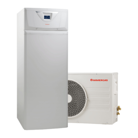
- Audax Pro 6-9 V2 outdoor unit (hereinafter referred to as outdoor unit or Audax Pro 6-9 V2). Magis Hercules Pro Mini 6-9 is perfectly operational only if the two units are correctly powered and interconnected. The UI MHPM indoor unit was designed solely for floor installation for heating and air conditioning and to produce domestic hot water for domestic use and similar purposes. - Page 8 Check the environmental operating conditions of all parts relevant to installation, referring to this booklet. If installing a kit or servicing the appliance, always empty the system’s domestic hot water circuit first so as not to compromise the appliance’s electrical safety (Par. 2.9, 2.10). Always disconnect the appliance from voltage and, depending on the type of operation, decrease the pressure and/or bring it to zero in the gas and DHW circuits.
- Page 9 They must be connected to a central heating system and domestic hot water circuit suited to their performance and capacity. The appliance is built to also operate in cooling mode. If cold water production, during summer, could interfere and damage the central heating only systems, necessary precautions must be taken to prevent that an unintentional production of cold water enters the heating only system.
-
Page 10: Indoor Unit Main Dimensions
- Chiller line - liquid phase - Filling - System return - System flow - Wall-mounted hydraulic connection with Immergas tem- - Domestic hot water outlet plate (*) - DHW (Domestic hot water) water inlet - Direct hydraulic connection in heat pump (*) -
Page 11: Minimum Indoor Unit Installation Distances
DIRECT HEAT PUMP CONNECTIONS RECIRCULA- CHILLER LINE DOMESTIC HOT WATER SYSTEM SOLAR SYSTEM TION M - R UCS - EFS SAE 1/4” SAE 5/8” G 3/4" G 1" G 3/4" G 1" G 3/4" WALL CONNECTIONS WITH TEMPLATE RECIRCULA- CHILLER LINE DOMESTIC HOT WATER SYSTEM SOLAR SYSTEM... -
Page 12: Indoor Unit Hydraulic Connection
In order to meet the system requirements established by EN 1717 in terms of pollution of drinking water, we recommend installing the IMMERGAS anti-backflow kit to be used upstream of the cold water inlet connection of the indoor unit. We also recommend using cat- egory 2 heat transfer fluid (ex: water + glycol) in the internal unit primary circuit (heating and/or cooling circuit), as defined in standard EN 1717. -
Page 13: Electrical Connection
ELECTRICAL CONNECTION Indoor unit electrical connection The internal unit has an IPX5D degree of protection; electrical safety of the appliance is achieved only when it is properly connected to an efficient earthing system, as specified by current safety standards. The manufacturer declines any responsibility for damage or physical injury caused by failure to connect the indoor unit to an efficient earthing system or failure to comply with the IEC reference standards. - Page 14 3. Unscrew the screws (g) (Fig. 6). 4. Open the main panel as shown in figure 7. 5. Undo the screws (h) and remove the cover (i) (Fig. 8). Ensure that the electrical installation corresponds to maximum absorbed power specifications as shown on the indoor unit data name- plate.
- Page 15 The power supply cable (l) must be laid as shown (Fig. 9). If the power supply cable is damaged, it must be replaced by a special cable or assembly, which are only available from the manufacturer or its Authorised After-Sales Technical Assistance Centre.
- Page 16 Electrical connections to the main panel The connection cables must follow the predetermined path using the special cable glands (a) (Fig.10). The electrical connections available are: • Zone 2 flow probe; Key (Fig. 10): • Zone 2 humidistat; - System resistance connection (optional) •...
- Page 17 Open the control panel connections compartment (Fig. 11). To carry out electrical connections, all you have to do is open the connections compartment as follows. 1. Remove the cover and the aesthetic profile. 2. Disassemble the cover. 3. Loosen the screws (a). 4.
- Page 18 TECHNICAL DATA MAINTENANCE TECHNICIAN USER INSTALLER Key (Fig. 12): - 2 direct zones kit - Supervision board - 2 zones kit (1 mixed and 1 direct) - Electronic expansion board (optional) B3-2 - Zone 2 flow probe (optional) - System integrative resistance kit 3 kW - 2 zones kit (1 mixed and 1 direct) E7-2 - Zone 2 safety thermostat (low temperature) (optional)
- Page 19 Key (Fig. 13): - External probe (optional) - Recirculation probe (optional) - Electronic expansion board (optional) S20-1 - Zone 1 room thermostat (optional) A17-1, 2 - Temperature sensor zone 1, 2 (optional) - Outdoor unit S36-1 - Zone 1 humidistat (optional) - Photovoltaic inlet (optional) - Dominus (optional) - Heating/Cooling Selector (optional)
-
Page 20: Remote Zone Control (Optional)
REMOTE ZONE CONTROL (OPTIONAL) This remote device is used to adjust the setpoints and to view the main information of the zone where it was configured. Connect the appliance as shown (Fig. 12). To correctly configure the device, set the parameters as described below: Assistance Menu ->... -
Page 21: Modbus Temperature And Humidity Room Probes (Optional)
MODBUS TEMPERATURE AND HUMIDITY ROOM PROBES (OPTIONAL) The Modbus temperature and humidity probe is used to detect the room temperature and humidity and to calculate the dew point. In addition, by setting the relative zone room setpoints available on the Control panel (see 2Par. 2.6), it is possible to check the tempera- ture and humidity of a room. -
Page 22: Room Chrono-Thermostats (Optional)
The indoor unit is prepared for the application of room chrono-thermostats, which are available as optional kits. A maximum of 3 temperature controllers can be applied directly to the appliance. All Immergas chrono-thermostats are connected with 2 wires only. Carefully read the user and assembly instructions contained in the accessory kit. -
Page 23: External Temperature Probe (Optional)
1.12 EXTERNAL TEMPERATURE PROBE (OPTIONAL) The outdoor unit has a standard external probe that can be used as an external probe of the heat pump. The external probe is used to: - Thermoregulate the water flow temperature; - Determine the use of additional generators (electrical resistances). If the outdoor unit is positioned in an area that is not suitable for temperature reading, it is advisable to use an additional external probe (Fig. -
Page 24: Temperature Control Setting
1.14 TEMPERATURE CONTROL SETTING By setting the parameters in the menus Zones/Configuration it is possible to automatically adjust the flow temperature of each zone according to the outdoor temperature. This can be done by enabling the external probe modulation in the menu Zones/Enablings The curves (Fig. -
Page 25: System Filling
1.15 SYSTEM FILLING Once the indoor unit is connected, fill the system using the filling cock (7, Fig. 27). The indoor unit has incorporated an automatic air vent valve on the internal inertia manifold. It is also necessary to provide a vent at the highest point of the heat pump return branch. With the installation of the optional connection unit, a manual deaerator is provided. -
Page 26: Indoor Unit Start-Up (Ignition)
1.17 INDOOR UNIT START-UP (IGNITION) After having installed the chiller lines on the outdoor unit, to commission the heat pump (the operations listed below must only be per- formed by qualified personnel and in the presence of staff only): 1. Check connection to a 230V~50Hz power mains, correct L-N polarity and the earthing connection; 2. -
Page 27: Upm4 Circulation Pump
1.18 UPM4 CIRCULATION PUMP The appliance is supplied with a variable speed pump that adjusts the speed to ensure the best possible performance. Pump LED. The LED flashes green when the pump is powered and the control signal is connected. The LED lights up steady green when the pump is powered and the signal cable disconnected. - Page 28 Head available to the system 1000 1200 1400 1600 1800 2000 2200 2400 2600 2800 3000 Key (Fig. 24): = Head available to the PWM system 100% = Head available to the PWM system 60% (minimum settable head for product with system integration resistance) = Head available to the PWM system 50% (minimum settable head for product without system integration resistance) = Power absorbed by pump PWM 50% = Power absorbed by pump PWM 60%...
-
Page 29: Domestic Hot Water Storage Tank Unit
1.19 DOMESTIC HOT WATER STORAGE TANK UNIT The storage tank in the appliance is an accumulation type with a capacity of 180 litres. It contains large coiled stainless steel heat exchanger pipes, which allow to notably reduce hot water production times. These storage tank units constructed with stainless steel casing and bottoms, guarantee long duration through time. -
Page 30: Kits Available On Request
Also make sure that the liquid contained in it cannot freeze. 1.20 KITS AVAILABLE ON REQUEST Check the complete list of kits available and which can be combined with the product, consult the Immergas website, the Im- mergas Price List or the technical-commercial documentation (catalogues and data sheets). -
Page 31: Main Components
1.21 MAIN COMPONENTS 10 11 13 14 15 16 17 Key (Fig. 27): - System expansion vessel - 3-way valve (motorised) - System return fitting - System safety valve - Storage tank draining valve - System flow fitting - Heat pump circulator - Sacrificial anode - Cold water inlet fitting - Inertial storage tank 25L... -
Page 32: Instructions For Use And Maintenance
INSTRUCTIONS FOR USE AND MAINTENANCE GENERAL RECOMMENDATIONS The device can be used by children at least 8 years old as well as by persons with reduced physical, sensory or mental capabilities, or lack of experience or required knowledge, provided that they are under surveillance, or after they have been instructed relat- ing to the safe use and have understood the potential dangers. -
Page 33: Cleaning And Maintenance
At the end of its service life, the appliance must not be disposed of like normal household waste nor abandoned in the environment, but must be removed by a professionally authorised com- pany as required by current legislation. Contact the manufacturer for disposal instructions. 2.2 CLEANING AND MAINTENANCE To preserve the system's integrity and keep the safety features, performance and reliability, which distinguish the assembly, unchanged over time, you must execute maintenance operations on a yearly basis in compliance with what is stated in the rela-... - Page 34 Once the device has been powered, it goes into the status prior to switch-off. Press the “MODE” button to cyclically select the desired op- erating mode amongst those available. The operating mode in use is indicated by its icon at the top of the display (Fig. 29) and is unique for all zones. By pressing any button, the pushbutton panel lights up for a few seconds;...
- Page 35 • Enter the menus The control panel menus can be accessed by pressing the buttons (Fig. 28): • Moving in the menus Simply rotate the “Set DHW (Domestic hot water)” knob to scroll the menu items. The indication “[...]” next to the menu item indicates the availability of a submenu. Press the “OK”...
-
Page 36: Operating Mode
2.5 OPERATING MODE The indoor unit can work in the following modes: – OFF; – STAND-BY ( – SUMMER ( – SUMMER WITH COOLING ( – WINTER ( If the indoor unit is at “OFF”, press the button “ ” to activate it. If this is not the case, go to the next point. Then press the “MODE”... - Page 37 The domestic hot water can be produced with the heat pump or with electrical resistance. The system automatically manages the activation of the generators to heat up the domestic hot water in the storage tank. During activation, 'DHW underway' appears on the display. It is possible to set the domestic hot water temperature adjustment in two ways: MANUAL or AUTOMATIC.
- Page 38 By associating a calendar with the relevant zone program, it is possible to determine the time slots for activating the central heating / C.H. comfort set. The time slots not set, correspond to the central heating / C.H. economy set. When the detected room temperature is below the central heating / C.H.
- Page 39 Dehumidify If the system is coupled to a humidistat (optional) or a remote zone panel (optional) or a temperature and humidity probe (optional), you can manage the room humidity in summer air conditioning mode. – If coupled to a humidistat, set the degree of humidity on the humidistat itself (see the instruction booklet). –...
- Page 40 • Time slots It is possible to set 4 calendars with 4 time operating slots in system comfort mode. The system will operate in economy mode during out-of-range time of these 4 time slots. After setting these 4 calendars it is possible to associate them to the various days of the week in the zone programs, DHW (Domestic hot water) and recirculation according to one's needs.
- Page 41 Heat pump disabling It is possible to disable the heat pump operation for a certain time slot, by setting User / Disable HP = Yes and the start and end times of disabling. Integration Disabling The use of the integration electrical resistances can be permanently disabled by setting User / Disable Integration = Yes Automatic Vent Function In the case of new systems and, in particular, for floor systems, it is very important that de-aeration is performed correctly.
- Page 42 Operation with external probe It is possible to use the thermoregulation functions associated to an external probe. The system is standard set up to use the outdoor unit external probe or an optional external probe. With the external probe connected and the thermoregulation function active, the system flow setpoint for room central heating / C.H. or cooling is managed by the system according to the outdoor temperature measured (Par.
-
Page 43: Parameters And Information Menu
PARAMETERS AND INFORMATION MENU Menu "DHW". Press the “DHW (Domestic hot water)” button to access a list of variables that enable you to customise use of the DHW (Domestic hot water). Hereunder is a list of available menus: The following menus refer to firmware rev. 1.2 Customised Menu item Description... - Page 44 Zones Menu. Press the “Zones” BUTTON to access a list of variables that enable you to customise use of the zones. Hereunder is a list of available menus: Zones Menu item Description Zone 1 Defines the operating parameters to manage zone 1. Zone 2 (*) Defines the operating parameters to manage the zone 2 (if present).
- Page 45 Zones / Zone 1 / Settings / C.H. Customised Menu item Description Range Default value Room setpoint in central heating zone 1 Comfort mode (Auto Comfort Set 10 ÷ 35 °C mode) Room setpoint in central heating zone 1 Economy mode (Auto Economy Set 5 ÷...
- Page 46 Zones / Zone 2 (*) Menu item Description Information This displays the system operating data. Settings Defines the operating parameters to manage the zone 2. Zones / Zone 2 (*) / Information Menu item Description Room temperature Room temperature on zone 2 Room humidity Zone 2 room humidity Dew temperature...
- Page 47 Zones / Zone 2 (*) / Settings / Cooling Customised Menu item Description Range Default value Room temperature in cooling zone 2 in Comfort mode (Auto Comfort Set 10 ÷ 35 °C mode) Room temperature in cooling zone 2 in Economy mode (Auto Economy Set 5 ÷...
- Page 48 Zones / Zone 3 (*) Menu item Description Information This displays the system operating data. Settings Defines the operating parameters to manage the zone 3. Zones / Zone 3 (*) / Information Menu item Description Room temperature Room temperature on zone 3 Room humidity Zone 3 room humidity Dew temperature...
- Page 49 Zones / Zone 3 (*) / Settings / Cooling Customised Menu item Description Range Default value Room temperature in cooling zone 3 in Comfort mode (Auto Comfort Set 10 ÷ 35 °C mode) Room temperature in cooling zone 3 in Economy mode (Auto Economy Set 5 ÷...
- Page 50 Zones / General settings Customised Menu item Description Range Default value Outside temperature External temper. detected by the external probe (optional) System flow set Flow temperature set on the system Zone 1 flow set Flow temperature set on zone 1 Request present on zone 1 No = no request CH = Central heating request...
- Page 51 Main Menu Press the “MENU” button to access a list of variables that enable you to customise use of the system. Hereunder is a list of available menus: Menu Menu item Description Clock and programs Defines the date/time and time operating slots User Defines the system parameters that can be modified by the user Information...
- Page 52 Customised Menu item Description Range Default value Zone 3 Program Zone 3 time scheduling (if present) CAL1, CAL2, Zone 3: Monday CAL1 CAL3,CAL4 CAL1, CAL2, Zone 3: Tuesday CAL1 CAL3,CAL4 CAL1, CAL2, Zone 3: Wednesday CAL1 CAL3,CAL4 CAL1, CAL2, Zone 3: Thursday CAL1 CAL3,CAL4 CAL1, CAL2,...
- Page 53 Customised Menu item Description Range Default value Recirculation Program Recirculation operation time programming CAL1, CAL2, Recirculation: Monday CAL1 CAL3,CAL4 CAL1, CAL2, Recirculation: Tuesday CAL1 CAL3,CAL4 CAL1, CAL2, Recirculation: Wednesday CAL1 CAL3,CAL4 CAL1, CAL2, Recirculation: Thursday CAL1 CAL3,CAL4 CAL1, CAL2, Recirculation: Friday CAL1 CAL3,CAL4 CAL1, CAL2,...
- Page 54 System resistance System resistance active control DHW resistance 1 Standard DHW (Domestic hot water) resistance active control System state Technical parameter (only for Immergas Assistance) Integration state Technical parameter (only for Immergas Assistance) Output status Technical parameter (only for Immergas Assistance)
- Page 55 Menu item Description Pump speed Heat pump circulator speed System flow temp. System temperature Heat. set correc. Current correction of the flow setpoint System flow rate Heat pump circuit flow rate Photovoltaic Operating status combined with a photovoltaic system Power reduction This displays a reduction of the PdC operating frequency Hot/Cold three-way Summer/Winter Three-way Position...
- Page 56 Menu / Anomalies log Menu item Description Reset anomalies Resets the list of anomalies Anomalies log Menu / Anomalies log / Anomalies log Menu item Description History index Anomaly code This displays the selected anomaly code Technical anomaly Menu / General information Customised Menu item Description...
-
Page 57: Fault And Anomaly Signals
FAULT AND ANOMALY SIGNALS The indoor unit indicates a possible anomaly through a code flanked by the symbol of a key " " in the centre of the display and the mes- sage "indoor unit anomaly" at the bottom of the display itself (Fig. 28). Error Anomaly signalled Cause... - Page 58 Error Anomaly signalled Cause Appliance status / Solution Code Zone 3 low If the board detects an anomaly on the zone 3 low tempera- temperature probe ture probe; the system cannot work in the affected area. anomaly Low-temperature During normal operation, if an anomaly causes excessive Zone 2 safety The unit does not meet the zone overheating of the flow temperature in the low temperature...
- Page 59 Error Anomaly signalled Cause Appliance status / Solution Code Zone 3 room temperature probe The zone 3 room probe has an out of range resistive value. error In addition to the humidity, the dew Zone 1 humidity point is not calculated for the zone Anomaly on the zone 1 humidity probe.
- Page 60 Error Anomaly signalled Cause Appliance status / Solution Code De-aeration in No demand can be made until the end Deaeration function in progress progress of the function in progress (1) Errore Dominus Communication with Dominus is offline offline Recirculation probe The board detects an anomaly on the D.H.W.
- Page 61 List of outdoor unit anomalies If the outdoor unit is faulty, the error code is displayed in the middle of the control panel (Fig. 28), with a key symbol next to it " ". In addition, the message "Outdoor unit anomaly" is displayed at the bottom of the display (Fig. 28). Error Code Anomaly signalled Hydronic module status / Solution...
- Page 62 Error Code Anomaly signalled Hydronic module status / Solution Check the position of the sensor. Check the relative wiring Compressor sensor error (overload protection sensor) Replace the sensor Check the chiller cycle. Freezing detection (during cooling operation) Check the temperatures of the plate heat exchanger Check the chiller cycle.
- Page 63 Error Code Anomaly signalled Hydronic module status / Solution Check the compressor connections and its normal operation. Check the resistances between the different phases of the compres- Compressor overload error sor. Check the input voltage. Low voltage error of DC circuit Check the power connections.
- Page 64 Error Code Anomaly signalled Hydronic module status / Solution Not present Not present Not present Not present Not present Not present Indoor unit error Not used Check indoor unit Indoor unit error Not used Check indoor unit Indoor unit error Not used Check indoor unit Indoor unit error...
-
Page 65: Restore Central Heating System Pressure
2.8 RESTORE CENTRAL HEATING SYSTEM PRESSURE 1. Periodically check the system water pressure (the indoor unit’s pressure gauge hand must indicate a value between 1 and 1.2 bar). 2. If the pressure falls below 1 bar (with the system cold) restore normal pressure via the valve located at the top of the appliance (Fig. 34). 3. -
Page 66: Emptying The D.h.w. Circuit
2.10 EMPTYING THE D.H.W. CIRCUIT To do this, always close the domestic cold water inlet upstream of the appliance. Open any domestic hot water tap to discharge the pressure from the circuit. Empty the storage tank completely as indicated in Par. 2.11 2.11 STORAGE TANK DRAINING To drain the storage tank, use the relevant storage tank draining valve (Det. -
Page 67: Instructions For Maintenance And Initial Check
These will also compromise the product’s compliance, and the said product may no longer be valid and fail to meet the current regulations. in regard to the above, only use original Immergas spare parts when replacing components. If additional documentation needs to be consulted for extraordinary maintenance, contact the Authorised After-Sales Service. -
Page 68: Yearly Appliance Check And Maintenance
YEARLY APPLIANCE CHECK AND MAINTENANCE The following checks and maintenance should be performed once a year to ensure operation, safety and efficiency of the appli- ance over time. - Check for water leaks or oxidation from/on the fittings. - Check, after discharging the system pressure and bringing it to zero (read on indoor unit pressure gauge), that the expansion vessel charge is at 1.0 bar. -
Page 69: Hydraulic Diagram
38 39 TECHNICAL DATA MAINTENANCE TECHNICIAN USER INSTALLER... - Page 70 Key (Fig. 35): - DHW recirculation pump (Optional) - DHW recirculation one-way valve (Optional) - Storage tank draining valve - DHW electrical resistance - DHW expansion vessel valve - Direct zone 1 pump (Optional) - Storage tank solar probe (Optional) - Zone 2 circulator (Optional) - Domestic hot water expansion vessel - Zone 2 safety thermostat (Optional)
-
Page 71: Wiring Diagram
Key (Fig. 36): - Black W/BK - White/Black - Blue - Orange - Supervision board - Brown - Purple - System flow-meter - Cyan - Pink - Flow meter Signal conversion relay - Green - Red - Main panel - Grey - White - Control panel - Yellow/Green... - Page 72 TECHNICAL DATA MAINTENANCE TECHNICIAN USER INSTALLER Key (Fig. 37): - Black - Pink - Blue - Red - Display board - Brown - White - Supervision board - Condensing unit interface board - Cyan - Yellow - Green - Touch keyboard - Grey - Control panel - Main panel...
- Page 73 X105 Terminal board connections diagram Key (Fig. 38): - Blue - Brown - Supervision board - Orange - Purple - Main panel - Pink - Red - Yellow...
- Page 74 TECHNICAL DATA MAINTENANCE TECHNICIAN USER INSTALLER Key (Fig. 39): - Main panel - Black - Control panel - Blue - Supervision board B1-HP - Flow probe - Brown - Cyan - D.H.W. probe - Green B5-HP - Return probe - Liquid phase probe - Grey - Orange - Flow meter Signal conversion relay...
- Page 75 Key (Fig. 40): - Main panel - Blue - Supervision board - 230 Vac, 50 Hz, 3 kW, 1.5 mm - Brown - Cyan E15-A - Domestic hot water integration resistance - Green - Control Phase fuse - Resistance Phase fuse - Grey - Yellow/Green K15-A - DHW integrative resistance relay...
- Page 76 Interface board - setting switch Key (Fig. 41): - Factory setting: do not change...
- Page 77 Interface board - indicator LED Key (Fig. 42): Red LED flashing = Communication between interface board and P.C.B. valid Green LED flashing = Communication between interface board and outdoor unit valid Yellow LED = Not Used Interface board - 7-segment display During normal operation, the display shows “A0”...
-
Page 78: System Filter
SYSTEM FILTER The unit is sold with a filter that must be installed on the system return pipe in order to preserve the proper functioning of the system. The filter can be cleaned periodically and when necessary. In order to preserve the proper functioning of the manifold within the hydraulic circuit, it is necessary for the inspection Y-fil- ter to work in a horizontal position. -
Page 79: Programming
P.C.B. PROGRAMMING The water heater is set up for possible programming of the operation parameters. By modifying these parameters as described below, the system can be adapted according to specific needs. To view the operation parameters of the "DHW" menu, enter the submenu "General information" and select "Access level". Enter the appropriate access code, exit the menu and press the "General information"... - Page 80 To view the operation parameters of the "Zones" menu, enter the submenu "General settings" and select "Access level". Enter the appropriate access code, exit the menu and press the "Zones" button (Fig. 28). To save the change of the parameters described below, press the "OK" button (Fig. 28). Exit the "Zones"...
- Page 81 Zones / Zone 1 / Configuration / Thermoreg. CH Customised Menu item Description Range Default value Without the external probe it defines the maximum flow temperature that can be set by the user. With the external probe Max flow set 20 ÷...
- Page 82 Zones / Zone 2 (*) / Configuration Menu item Description Enablings Thermoreg. CH Central heating thermoregulation setting sub-menu Thermoreg. Cool. Cooling thermoregulation setting sub-menu Zones / Zone 2 (*) / Configuration / Enablings Customised Menu item Description Range Default value Mode Establishes the zone 2 operating mode Cool.
- Page 83 Zones / Zone 2 (*) / Configuration / Thermoreg. CH Customised Menu item Description Range Default value Without the external probe it defines the maximum flow temperature that can be set by the user. With the external probe Max flow set 20 ÷...
- Page 84 Zones / Zone 3 (*) / Configuration Menu item Description Enablings Thermoreg. CH Central heating thermoregulation setting sub-menu Thermoreg. Cool. Cooling thermoregulation setting sub-menu Zones / Zone 3 (*) / Configuration / Enablings Customised Menu item Description Range Default value Mode Establishes the zone 3 operating mode Cool.
- Page 85 Zones / Zone 3 (*) / Configuration / Thermoreg. CH Customised Menu item Description Range Default value Without the external probe it defines the maximum flow temperature that can be set by the user. With the external probe Max flow set 20 ÷...
- Page 86 To access the "Support" menu, press the "MENU" button (Fig. 28). Go to the submenu "General settings" and select "Access level". Insert the relative access code and customise the parameters described below according to your requirements. To save the change of the parameters described below, press the "OK" button (Fig. 28). Exit the "Support"...
- Page 87 Menu / Support / System definition Customised Menu item Description Range Default value Number of zones Defines the number of zones present Defines the main zone of the system in which the remote panel Main zone 1-2-3 will be used This defines the type of external probe enabled.
- Page 88 Menu / Support / Heat pump Menu item Description Powers Timers Pump Menu / Support / Heat pump / Powers Customised Menu item Description Range Default value MHP / MHP HP Type Setting the indoor unit model MHP Mini Mini HP Model Setting the connected outdoor unit.
- Page 89 Menu / Support / Integration Customised Menu item Description Range Default value Temperature threshold below which integration is activated at Min. integration temp. -25 ÷ +35 °C (*) the heat pump. Mode of intervention of the DHW (Domestic hot water) DHW integration mode.
- Page 90 Menu / Support / Manual drives(*) Customised Menu item Description Range Default value Sys./DHW 3-way Manual activation of the DHW (Domestic hot water) 3-way Yes / No Enable sys.resistance Manual activation of the system resistance Yes / No Manual activation of the DHW (Domestic hot water) resistance Enable DHW resistance 1 Yes / No Zone 1 circulator...
- Page 91 Menu / Support / Special parameters Customised Menu item Description Range Default value Dehumid. in cool.air Dehumidification control in cooled air (0 = zone 2, 1 = zone 1) Safety therm. Zone 2 Zone 2 safety thermostat 20-80 Safety therm. Zone 3 Zone 3 safety thermostat 20-80 Enable recirculation (*)
-
Page 92: First Ignition Parameter Setting
3.10 FIRST IGNITION PARAMETER SETTING During the first activation of the appliance, it is necessary to customise the following parameters, which concern the generator opera- tion, the type of outdoor unit and the type of system connected to the appliance. In the menu Support / Heat pump / HP Type you must ensure that the model set is 'MHP Mini'. - Page 93 The first served operating mode, in case of contemporaneity, is decided with the parameter: Configuration / Priority The DHW Mode can have a maximum duration, settable with the parameter Configuration / Max time DHW beyond which the alarm is signalled. The heat pump can manage up to 3 distribution pumps.
-
Page 94: Dhw (Domestic Hot Water) Boost Function
3.11 DHW (DOMESTIC HOT WATER) BOOST FUNCTION In order to activate the DHW (Domestic hot water) BOOST function, it is necessary to enable the DHW (Domestic hot water) electrical resistance by changing the parameter: Integration / Enable DHW integr. 3.12 ANTI-LEGIONELLA FUNCTION The indoor unit is equipped with a function to perform a thermal shock on the storage tank. -
Page 95: Pump Anti-Block Function
3.14 PUMP ANTI-BLOCK FUNCTION The indoor unit has a function that starts the pump at least once every 24 hours for the duration of 30 seconds in order to reduce the risk of the pump becoming blocked due to prolonged inactivity. 3.15 THREE-WAY ANTI-BLOCK SYSTEM The indoor unit has a function that activates the motorised three-way unit 24 hours after the last time it operated by running a complete cycle in order to reduce the risk of the three-way blocking due to prolonged inactivity. -
Page 96: Integration With System Internal Electrical Resistance
3.17 INTEGRATION WITH SYSTEM INTERNAL ELECTRICAL RESISTANCE. The heat pump can be added with a system electrical resistance (optional) to be installed inside the appliance, to have an alternative source of energy available for use in central heating mode. Enabling the electrical resistance is done via a single parameter. Modifying the parameter Integration / Enable heat.integr. -
Page 97: Integration With System External Electrical Resistance
For the electrical connection see the reference wiring diagram (Fig. 12). If one or more external electric resistances are installed in combination with one of the two-zone kits (supplied by Immergas), integration must be installed between the UI MHPM indoor unit and the distribution kit. -
Page 98: Heat Pump Disabling Function
3.21 HEAT PUMP DISABLING FUNCTION No request will be met, excluding the safety functions. To enable this function, please edit the following parameters: Heat pump / Powers / HP power off = Yes User / Disable HP = Yes One can then choose whether to activate the disabling according to a schedule by setting time slots in the menu: User / Start hourly HP disab. -
Page 99: External Probe Setting
The appliance can be configured so that it can be controlled by the external supervision devices such as Dominus or other types of home automation systems (not supplied by Immergas). For the configuration, it is necessary to modify the parameter System definition / System supervision It is not possible to configure both devices simultaneously. -
Page 100: Access To Control Panel And Electrical Panel
3.31 ACCESS TO CONTROL PANEL AND ELECTRICAL PANEL Follow the instructions below to gain access to the control panel and main electrical panel: - Remove the plastic protection caps (2) and loosen the screws (3) to remove the aesthetic profile (1). - Open the cover door (4) to make it tilt. - Page 101 - Unscrew the 3 fixing screws (7) on the control panel. - After which, pull the control panel (8) towards you and turn it as shown in the figure 46.
- Page 102 - Unscrew the 4 screws (9). - Open the main panel (10) as shown in figure 48.
-
Page 103: Casing Removal
3.32 CASING REMOVAL To facilitate indoor unit maintenance the casing can be completely removed as follows: Aesthetic profile (1) (Fig. 43). - Remove the plastic protection caps (2) and loosen the screws (3) to remove the aesthetic profile (1). Cover disassembly (4) (Fig. 44). - Open the cover door (4) to make it tilt. - Page 104 Disassembly of casing sides (9 and 10) (Fig. 50) - Remove the left and right sides (9 and 10) by unscrewing the screws (11 and 12) present; then push slightly upwards to release the sides from their seats and pull upwards (Det. A).
-
Page 105: Technical Data
TECHNICAL DATA TECHNICAL DATA TABLE The following data refers to product data. MAGIS HERCULES MAGIS HERCULES PRO MINI 6 PRO MINI 9 Nominal data for low temperature applications (A7/W35) * Nominal central heating output 6,00 9,00 Absorption 1,22 1,87 kW/kW 4,92 4,81 Nominal data for low temperature applications (A35/W18) *... - Page 106 Indoor unit data UI MHPM6 UI MHPM9 Dimensions (Width x Height x Depth) 600x1600x675 Water content 26,2 System expansion vessel volume System expansion vessel pre-charged pressure Hydraulic circuit max. operating pressure Domestic hot water circuit min. dynamic pressure Domestic hot water circuit pressure DHW (Domestic hot water) expansion vessel volume DHW expansion vessel pre-charged pressure Storage tank water content...
-
Page 107: Magis Hercules Pro Mini 6 Product Fiche (In Compliance With Regulation 811/2013)
MAGIS HERCULES PRO MINI 6 PRODUCT FICHE (IN COMPLIANCE WITH REGULATION 811/2013) Supplier's name or trademark Immergas S.p.A MAGIS HERCULES Supplier's model identifier PRO MINI 6 For space heating Application temperature Average temperature For water heating Stated load profile Average temperature... - Page 108 4.3 TABLE 2 REGULATION 813/2013 Model MAGIS HERCULES PRO MINI 6 Air/water heat pump Low temperature heat pump Water/water heat pump With Supplementary heater Brine/water heat pump Mixed central heating device with heat pump: The parameters are declared for average temperature application, except for low temperature heat pumps. The parameters for low temperature heat...
-
Page 109: Magis Hercules Pro Mini 9 Product Fiche (In Compliance With Regulation 811/2013)
MAGIS HERCULES PRO MINI 9 PRODUCT FICHE (IN COMPLIANCE WITH REGULATION 811/2013) Supplier's name or trademark Immergas S.p.A MAGIS HERCULES Supplier's model identifier PRO MINI 9 For space heating Application temperature Average temperature For water heating Stated load profile Average temperature... - Page 110 For mixed central heating appliances with a heat pump Stated load profile Water central heating energy efficiency η Daily electrical power consumption 7,46 kWh Daily fuel consumption elec fuel Annual energy consumption 1595 kWh Annual fuel consumption Contact information Immergas S.p.A. via Cisa Ligure n.95...
-
Page 111: Parameters For Filling In The Package Fiche
PARAMETERS FOR FILLING IN THE PACKAGE FICHE Should you wish to install an assembly starting from the Magis Hercules Pro Mini package, use the package fiche shown in (Fig. 52). To fill it in correctly, enter the figures shown in tables in par. "Parameters to fill in the low temperature package fiche (30/35)", "Parameters to fill in the average temperature package fiche (47/55)"... - Page 112 Parameters to fill in the low temperature package fiche (30/35) MAGIS HERCULES PRO MINI 6 Parameter Colder zones Average zones Hotter zones "I" 140,0 178,0 235,0 "II" "III" 5,35 4,45 4,45 "IV" 2,09 1,74 1,74 MAGIS HERCULES PRO MINI 9...
- Page 113 Room central heating system package fiche. ____ Temperature control Class I = 1 %, Class II = 2 %, Class III = 1.5 %, Class IV = 2 %, From temperature Class V = 3 %, Class VI = 4 %, control board Class VII = 3.5 %, Class VIII = 5 % Supplementary boiler...
- Page 116 This instruction booklet is made of ecological paper. immergas.com Immergas S.p.A. 42041 Brescello (RE) - Italy Tel. 0522.689011 Fax 0522.680617...