Table of Contents
Advertisement
Quick Links
Advertisement
Table of Contents

Related Manuals for York MILLENNIUM YCAL0043SC


Summary of Contents for York MILLENNIUM YCAL0043SC
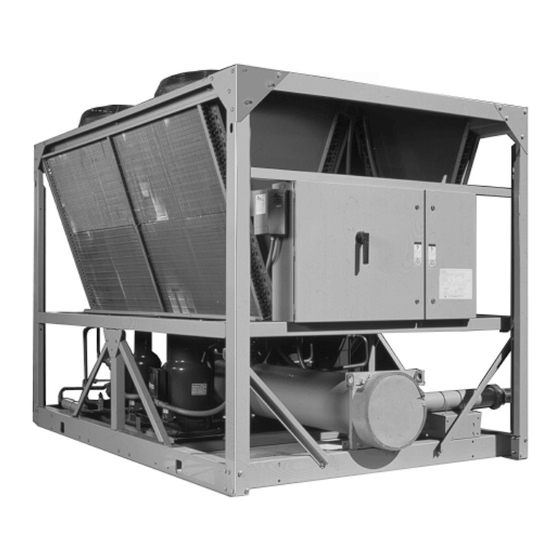
- Page 1 ® MILLENNIUM AIR-COOLED LIQUID CHILLERS HERMETIC SCROLL INSTALLATION, OPERATION, MAINT. Supersedes: Nothing Form 150.62-NM2 (699) See Literature Supplement at end of this manual, 150.62-NM2 (LS2) YCAL0043SC - YCAL0253SC 29224(R)A 380 - 415/3/50 MODEL ONLY Standard, Glycol & Metric Models, Combined...
-
Page 2: Table Of Contents
TROUBLESHOOTING CHARTS ..............99 MAINTENANCE ..................... 102 ISN CONTROL ....................103 APPENDIX 1 – DIMENSIONS ................ 122 YORK APPLIED SYSTEMS FIELD OFFICE LISTING ........128 TABLES ELECTRICAL DATA ................19 STANDARD POWER CONNECTIONS ........... 20 – 21 SINGLE POINT POWER CONNECTIONS ........22 – 23 TEMPERATURES AND FLOWS (ENGLISH) ........... - Page 3 LOW AMBIENT CONDENSER FAN CONTROL – DISCHARGE PRESSURE CONTROL ................ 85 COMPRESSOR OPERATION – LOAD LIMITING ........86 MICROBOARD BINARY INPUTS ............91 MICROBOARD ANALOG INPUTS ............91 MICROBOARD OUTPUTS ..............91 OUTDOOR AIR SENSOR VALUES ............93 YORK INTERNATIONAL...
- Page 4 ELEMENTARY DIAGRAM ............118 – 119 ELEMENTARY DIAGRAM – POWER CIRCUIT ......120 – 121 TYPE CP 1 ................... 124 TYPE CP 2 ................... 124 R SPRING SEISMIC ISOLATOR ............125 TYPE CP MPOUNTING ................ 126 “AEQM” SPRING-FLEX MOUNTING ............. 127 YORK INTERNATIONAL...
-
Page 5: Manual Usage And Revisions
In complying with YORK’s policy for continuous product improvement, the information contained in this document is subject to change without notice. While YORK makes no commitment to update or provide current information auto- matically to the manual owner, that information, if applicable, can be obtained by contacting the nearest YORK Service office. -
Page 6: Product Identification Number
NOMINAL CAPACITY UNIT DESIGNATOR REFRIGERANT VOLTAGE/STARTER DESIGN/DEVELOPMENT LEVEL : Standard Unit :380-415/3/50 :R-22 :Design Series A : YORK :Engineering : Chiller 60HZ: Nominal Tons: Even Number Change : Air-Cooled 50HZ: Nominal kW: Odd Number or PIN Level : Condensing Unit... - Page 7 OPTIONS MODEL NUMBER 16 17 18 19 20 21 22 23 24 25 26 27 28 29 30 31 32 33 34 35 3637 POWER FIELD CONTROLS FIELD COMPRESSOR / PIPING FIELD : Temp. Brine (LBrT) : MP Supply TB : Low Ambient Kit (factory) : SP Supply TB : High Ambient Kit (factory)
-
Page 8: Refrigerant Flow Diagram
LOW PRESSURE SWITCH OR RETURN WATER SUCTION PRESSURE TRANSDUCER TEMP. SENSOR LEAVING ENTERING CHILLED WATER CHILLED WATER LEAVING CHILLED WATER TEMP. SENSOR OIL EQUALIZING LINE 2 OR 3 COMPRESSORS PER SYSTEM LD04495 FIG. 1 – REFRIGERANT FLOW DIAGRAM YORK INTERNATIONAL... - Page 9 YORK service mechanic or a qualified service person The unit should be lifted by inserting hooks through experienced in chiller installation.
- Page 10 The unit should be mounted on a flat and level founda- lished in the YORK Engineering Guide for the specific tion, floor, or rooftop capable of supporting the entire chiller model. Sound blankets for the compressors and operating weight of the equipment.
- Page 11 The necessary components must be obtained 7. A chilled water flow switch, (either by YORK or others) in the field. MUST be installed in the leaving water piping of the cooler.
- Page 12 See Figure 5 and unit wiring diagram. To remotely start and stop the chiller, dry contacts can be wired in series with the flow switch and CTB2 - termi- nals 13 to 14. Refer to figure 5 and unit wiring diagram. YORK INTERNATIONAL...
- Page 13 115 VAC POWER FROM THE UNIT, AT OR BELOW FREEZING TEM- PERATURES, CAN RESULT IN DAMAGE TO THE EVAPRORATOR AND UNIT AS A RESULT OF THE CHILLED LIQUID FREEZING. Electrical Notes and Legend located on Page 17 and 18. FIG. 2 – STANDARD POWER SUPPLY WIRING YORK INTERNATIONAL...
-
Page 14: Optional Single Point Power Supply Wiring
115 VAC POWER FROM THE UNIT, AT OR BELOW FREEZING TEM- PERATURES, CAN RESULT IN DAMAGE TO THE EVAPRORATOR AND UNIT AS A RESULT OF THE CHILLED LIQUID FREEZING. Electrical Notes and Legend located on Page 17 and 18. FIG. 3 – OPTIONAL SINGLE POINT POWER SUPPLY WIRING YORK INTERNATIONAL... -
Page 15: N-F Disc Sw Or Circ Bkr
115 VAC POWER FROM THE UNIT, AT OR BELOW FREEZING TEM- PERATURES, CAN RESULT IN DAMAGE TO THE EVAPRORATOR AND UNIT AS A RESULT OF THE CHILLED LIQUID FREEZING. Electrical Notes and Legend located on Page 17 and 18. FIG. 4 – OPTIONAL SINGLE POINT POWER WIRING YORK INTERNATIONAL... -
Page 16: Control Wiring
THE UNIT EVAPORATOR HEATER USES 115 VAC. DISCONNECTING 115 VAC POWER FROM THE UNIT, AT OR BELOW FREEZING TEM- PERATURES, CAN RESULT IN DAMAGE TO THE EVAPRORATOR AND UNIT AS A RESULT OF THE CHILLED LIQUID FREEZING. FIG. 5 – CONTROL WIRING YORK INTERNATIONAL... -
Page 17: Electrical Notes
This disconnect is not intended to be a Load Break Device. 9. Field Wiring by others which complies to the National Electrical Code and Local Codes. YORK INTERNATIONAL... - Page 18 MINIMUM MIN NF MINIMUM NON FUSED RATED LOAD AMPS S.P. WIRE SINGLE POINT WIRING UNIT MOUNTED SERVICE (NON-FUSED DISCONNECT UNIT MTD SERV SW SWITCH) LOCKED ROTOR AMPS VOLTAGE CODE -50 = 380-415/3/50 LEGEND: Factory Supplied Supplied by Others YORK INTERNATIONAL...
-
Page 19: Electrical Data
ING POWER, PRIOR TO WORKING ON EQUIPMENT. THE UNIT EVAPORATOR HEATER USES 115 VAC. DISCONNECTING 115 VAC POWER FROM THE UNIT, AT OR BELOW FREEZING TEM- PERATURES, CAN RESULT IN DAMAGE TO THE EVAPRORATOR AND UNIT AS A RESULT OF THE CHILLED LIQUID FREEZING. YORK INTERNATIONAL... -
Page 20: Installation
MODELS w/o 115-1-60/50 30 A / 240V CONTROL TRANS MODELS w/ 380/415-1-50 30 A / 480V CONTROL TRANS A. Minimum #14 AWG, 75°C, Copper Recommended B. Minimum and Maximum Over Current Protection, Dual Element Fuse or Circuit Breaker YORK INTERNATIONAL... - Page 21 1 7 0 22.3 1 7 0 1 0 0 1 0 0 1 1 0 1 0 0 1 1 0 # 2 - 1/0 25.8 1 7 5 25.8 1 7 5 25.8 1 7 5 YORK INTERNATIONAL...
-
Page 22: Single Point Power Connections
2/0 - 4/0 0253SC 380/415 1 7 7 2 0 0 2 0 0 2 0 0 2 0 0 2 0 0 3/0 - 250 3/0 - 250 3/0 - 250 See Notes on pages 17 & 18. YORK INTERNATIONAL... - Page 23 1 7 5 22.3 1 7 0 22.3 1 7 0 22.3 1 7 0 25.8 1 7 5 25.8 1 7 5 25.8 1 7 5 25.8 1 7 5 25.8 1 7 5 25.8 1 7 5 YORK INTERNATIONAL...
- Page 24 1. Standard units cannot be operated below 40°F leaving chilled water temperature. 2. For leaving water temperature higher than 55°F, contact the nearest YORK Office for application guidelines. 3. The evaporator is protected against freeze-up to -20.0°F with an electrical heater as standard.
-
Page 25: Ethylene Glycol Correction Factors
87SC ETHYLENE POINT 107SC COMPR. DELTA GPM/°F/ GLYCOL TONS (°F) 117SC, 133SC, 147SC, 157SC,173SC .994 .997 1.03 24.1 197SC, 217SC, 237SC .986 .993 1.06 24.9 253SC .979 .990 1.09 25.9 .970 .985 1.13 27.3 .959 .980 1.16 29.0 YORK INTERNATIONAL... - Page 26 1. Standard units cannot be operated below 4.4°C leaving chilled water temperature. 2. For leaving water temperature higher than 12.8°C, contact the nearest YORK Office for application guidelines. 3. The evaporator is protected against freeze-up to -28.9°C with an electrical heater as standard.
-
Page 27: Ethylene Glycol Correction Factors
ETHYLE- POINT 107SC COMPR. DELTA GPM/°F/ TONS (°F) 117SC, 133SC, 147SC, GLYCOL 157SC, 173SC .994 .997 1.03 24.1 197SC, 217SC, 237SC, .986 .993 1.06 24.9 253SC .979 .990 1.09 25.9 .970 .985 1.13 27.3 .959 .980 1.16 29.0 YORK INTERNATIONAL... -
Page 28: Physical Data
Aluminum Fin Coils, lbs 2225 2241 2435 2647 3129 4363 4400 Copper Fin Coils, lbs 2392 2402 2619 2947 3468 4750 4786 Refrigerant Charge, R22, ckt1 / ckt2, lbs 45/45 54/54 Oil Charge, ckt1 / ckt2, gallons 2.0/2.0 2.1/2.1 YORK INTERNATIONAL... - Page 29 4610 4688 5275 5735 5925 6247 6 6 1 1 4462 4540 4836 5501 5616 5863 6128 4850 4928 5515 6029 6219 6541 6919 54/54 60/54 72/72 75/62 75/75 92/83 100/100 2.1/2.1 3.5/2.1 3.5/3.5 3.2/3.0 3.2/3.2 5.2/3.2 5.2/5.2 YORK INTERNATIONAL...
-
Page 30: Physical Data (Metric)
1 1 0 4 1201 1419 1979 1996 Copper Fin Coils, kg 1085 1090 1 1 8 8 1337 1573 2155 2171 Refrigerant Charge, R22, ckt1 / ckt2, kg 21/21 24/20 Oil Charge, ckt1 / ckt2, liters 8.0/8.0 8.0/8.0 YORK INTERNATIONAL... - Page 31 2414 2526 2640 2091 2126 2393 2601 2687 2834 2999 2024 2059 2194 2495 2547 2659 2780 2200 2235 2502 2735 2821 2967 3139 25/25 37/25 33/33 34/28 34/34 42/38 46/46 8.0/8.0 13/8 13/13 12/11.4 12.0/12.0 20/12 20/20 YORK INTERNATIONAL...
- Page 32 Site restrictions may compromise minimum clearances indicated below, resulting in unpredictable airflow patterns and possible diminished performance. YORK’s unit controls will optimize operation without nuisance high-pressure safety cutouts; however, the system designer must consider potential perfor- mance degradation.
- Page 33 FORM 150.62-NM2 DIMENSIONS (ENGLISH) YCAL0043SC - YCAL0057SC LD04402 TABLE 14 – WEIGHT DISTRIBUTION/CENTER OF GRAVITY MODEL WEIGHT DISTRIBUTION CENTER OF GRAVITY YCAL0 TOTAL 043SC 2225 50.1 25.8 23.3 057SC 2241 50.2 25.9 23.2 YORK INTERNATIONAL...
- Page 34 Site restrictions may compromise minimum clearances indicated below, resulting in unpredictable airflow patterns and possible diminished performance. YORK’s unit controls will optimize operation without nuisance high-pressure safety cutouts; however, the system designer must consider potential perfor- mance degradation.
- Page 35 FORM 150.62-NM2 DIMENSIONS (ENGLISH) YCAL0073SC - YCAL0107SC LD04404 TABLE 15 – WEIGHT DISTRIBUTION/CENTER OF GRAVITY MODEL WEIGHT DISTRIBUTION CENTER OF GRAVITY YCAL0 TOTAL 073SC 2435 50.6 25.9 28.5 087SC 2647 50.6 25.8 28.9 107SC 3129 48.0 25.4 26.9 YORK INTERNATIONAL...
- Page 36 Site restrictions may compromise minimum clearances indicated below, resulting in unpredictable airflow patterns and possible diminished performance. YORK’s unit controls will optimize operation without nuisance high-pressure safety cutouts; however, the system designer must consider potential perfor- mance degradation.
- Page 37 40.3 28.9 133SC 1118 1082 1118 1082 4400 58.6 40.5 28.7 147SC 1133 1098 1133 1098 4462 58.7 40.3 28.6 157SC 1151 1119 1151 1119 4540 58.8 40.5 28.4 173SC 1217 1201 1217 1201 4836 59.2 40.3 29.9 YORK INTERNATIONAL...
- Page 38 Site restrictions may compromise minimum clearances indicated below, resulting in unpredictable airflow patterns and possible diminished performance. YORK’s unit controls will optimize operation without nuisance high-pressure safety cutouts; however, the system designer must consider potential perfor- mance degradation.
- Page 39 YCAL0 TOTAL 197SC 1463 1288 1463 1288 5501 56.3 46.0 30.1 217SC 1492 1315 1492 1315 5616 56.3 45.6 30.1 237SC 1551 1380 1551 1380 5863 56.5 45.9 31.0 253SC 1620 1444 1620 1444 6128 56.6 45.6 30.8 YORK INTERNATIONAL...
- Page 40 Site restrictions may compromise minimum clearances indicated below, resulting in unpredictable airflow patterns and possible diminished performance. YORK’s unit controls will optimize operation without nuisance high-pressure safety cutouts; however, the system designer must consider potential perfor- mance degradation.
- Page 41 FORM 150.62-NM2 DIMENSIONS (METRIC) YCAL0043SC - YCAL0057SC LD04410 All dimensions in millimeters unless otherwise noted. TABLE 18 – WEIGHT DISTRIBUTION/CENTER OF GRAVITY MODEL WEIGHT DISTRIBUTION (kg) CENTER OF GRAVITY (mm) YCAL0 TOTAL 043SC 1009 1274 057SC 1016 1274 YORK INTERNATIONAL...
- Page 42 Site restrictions may compromise minimum clearances indicated below, resulting in unpredictable airflow patterns and possible diminished performance. YORK’s unit controls will optimize operation without nuisance high-pressure safety cutouts; however, the system designer must consider potential perfor- mance degradation.
- Page 43 FORM 150.62-NM2 DIMENSIONS (METRIC) YCAL0073SC - YCAL0107SC LD04412 All dimensions in millimeters unless otherwise noted. TABLE 19 – WEIGHT DISTRIBUTION/CENTER OF GRAVITY MODEL WEIGHT DISTRIBUTION CENTER OF GRAVITY YCAL0 TOTAL 073SC 1104 1285 087SC 1201 1285 107SC 1419 1220 YORK INTERNATIONAL...
- Page 44 Site restrictions may compromise minimum clearances indicated below, resulting in unpredictable airflow patterns and possible diminished performance. YORK’s unit controls will optimize operation without nuisance high-pressure safety cutouts; however, the system designer must consider potential perfor- mance degradation.
- Page 45 All dimensions in millimeters unless otherwise noted. TABLE 20 – WEIGHT DISTRIBUTION/CENTER OF GRAVITY MODEL WEIGHT DISTRIBUTION CENTER OF GRAVITY YCAL0 TOTAL 117SC 1979 1488 1022 133SC 1996 1489 1028 147SC 2024 1491 1022 157SC 2059 1493 1028 173SC 2194 1503 1022 YORK INTERNATIONAL...
- Page 46 Site restrictions may compromise minimum clearances indicated below, resulting in unpredictable airflow patterns and possible diminished performance. YORK’s unit controls will optimize operation without nuisance high-pressure safety cutouts; however, the system designer must consider potential perfor- mance degradation.
- Page 47 All dimensions in millimeters unless otherwise noted. TABLE 21 – WEIGHT DISTRIBUTION/CENTER OF GRAVITY MODEL WEIGHT DISTRIBUTION CENTER OF GRAVITY YCAL0 TOTAL 197SC 2495 1430 1167 217SC 2547 1430 1159 237SC 2659 1436 1167 253SC 2780 1437 1159 YORK INTERNATIONAL...
-
Page 48: Pre-Startup Checklist
Low Amb. Temp. Cutout 8. Visually inspect wiring (power and control). Wir- Leaving Liquid Temp. Cutout ing MUST meet local codes. See Figures 2 - 5. Anti-Recycle Time Fan Control On-Pressure Fan Differencial Off-Pressure Total # of Compressors YORK INTERNATIONAL... -
Page 49: Initial Startup
The chilled liquid setpoint may need to liquid line saturation temperature at the liquid stop valve be temporarily lowered to ensure all (liquid line saturation temp. is converted from a tempera- compressors cycle “on.” ture/pressure chart). YORK INTERNATIONAL... - Page 50 If the unit is functioning satisfactorily during the initial perature corresponding to the suction pressure as shown operating period, no safeties trip and the compressors in a standard pressure/temperature chart. cycle to control water temperature to setpoint, the chiller is ready to be placed into operation. YORK INTERNATIONAL...
-
Page 51: Unit Operating Sequence
180 seconds, which ever comes 4. Several seconds after the compressor starts, that first. systems first condenser fan will be cycled on (out- YORK INTERNATIONAL... -
Page 52: Unit Controls
YORK MILLENNIUM CONTROL CENTER 00065VIP INTRODUCTION MICROPROCESSOR BOARD The YORK MicroComputer Control Center is a micropro- The Microprocessor Board is the controller and deci- cessor based control system designed to provide the sion maker in the control panel. System inputs such as entire control for the liquid chiller. - Page 53 General Status and Fault Sta- Display Messages may show characters indicating tus. “greater than” (>) or “less than” (<). These characters indicate the actual values are greater than or less than the limit values which are being displayed. YORK INTERNATIONAL...
- Page 54 R U N P E R M I S S I V E NO RUN PERM shows that either the flow switch is open or a remote start/stop contact is open in series with the flow switch. YORK INTERNATIONAL...
- Page 55 Reloading the af- This message is displayed when the system is unable fected system will occur when the discharge pressure to start due the anti-recycle timer being active. drops to 85% of the unload pressure and 10 minutes have elapsed. YORK INTERNATIONAL...
- Page 56 STATUS display mode. Therefore, do not expect to see any other STATUS messages when in the YORK INTERNATIONAL...
- Page 57 30 seconds. If at any time during this 30 sec- onds the suction pressure falls below the ramped cut- out, the system will stop. This transient protection scheme only works if the suction pressure transducer is installed. When using the mechanical LP switch, the YORK INTERNATIONAL...
- Page 58 115VAC to the micropanel drops below a certain level, a unit fault is initiated to safely shut down the unit. Re- start is allowed after the unit is fully powered again and the anti-recycle timers have finished counting down. YORK INTERNATIONAL...
-
Page 59: Status Key
No Cooling load System X Comps Run System X AR Timer System X AC Timer System X Disch Limiting System X Suction Limiting System X Percentage Load Limiting Manual Overide Status System X Pumping Down (on shutdown) LD04144 YORK INTERNATIONAL... -
Page 60: Display/Print Keys
UP and This display shows the ambient air temperature. The DOWN arrow keys located under the “ENTRY” section. minimum limit on the display is 0.4°F (-17.6°C). The maximum limit on the display is 131.2°F (55.1°C). YORK INTERNATIONAL... - Page 61 2 switches to the lead system when pro- The second message shows the number of starts for grammed for AUTOMATIC LEAD/LAG. each compressor on each system. YORK INTERNATIONAL...
- Page 62 However, stage 3 may be shown in this display *PWM TEMP – EMS-PWM temperature reset without a low ambient kit added, but it has no effect. See the section on Condenser Fan Control in the Unit Operation section. *Refer to the section on Operating Controls YORK INTERNATIONAL...
- Page 63 Evaporator Pump Contacts & Heater Status Remote Control Active? *System X Number of Comp. Running *System X Run Time Sys 1 LLSV & HGSV Status *System X Condenser Fan Staging LD03684 * Block of information repeats for each system YORK INTERNATIONAL...
- Page 64 0- 0- 0- 0 D-H-M-S SUCTION PRESSURE 66 PSIG DISCHARGE PRESSURE 219 PSIG SUCTION TEMPERATURE 52.8 DEGF YORK INTERNATIONAL CORPORATION LIQUID LINE SOLENOID MILLENNIUM LIQUID CHILLER HOT GAS BYPASS VALVE UNIT STATUS CONDENSER FAN STAGES 2:04PM 01 JAN 99 SYS 1...
- Page 65 The information is stored at the instant of the fault, re- gardless of whether the fault caused a lockout to occur. YORK INTERNATIONAL CORPORATION The information is also not affected by power failures MILLENNIUM LIQUID CHILLER (long term internal memory battery back-up is built into the circuit board) or manual resetting of a fault lock-out.
- Page 66 Explanation of the above displays are covered under the L E A V I N G L I Q U I D T E M P STATUS, DISPLAY/PRINT, SETPOINTS, or UNIT keys. C U T O U T X X X . X ° F YORK INTERNATIONAL...
-
Page 67: "Entry" Keys
UP and DOWN arrow keys. The UP and DOWN arrow keys are also used for pro- gramming the control panel such as changing cooling setpoints, setting the daily schedule, changing safety setpoints, chiller options, and setting the clock. YORK INTERNATIONAL... -
Page 68: Setpoints Key
COOLING SETPOINTS key. After pressing into the evaporator. the COOLING SETPOINTS key, the Cooling Mode (leav- ing chilled liquid or return chilled liquid) will be displayed for a few seconds, and then the setpoint entry screen will be displayed. YORK INTERNATIONAL... - Page 69 DOWN arrow will change the setpoint in .5°F increments. After using the UP and DOWN arrows to adjust to the desired setpoint, the ENTER/ADV key must be pressed to enter this number into memory and advance to the RANGE SETPOINT. YORK INTERNATIONAL...
- Page 70 Refer to Engineering Guide for operation below 30°F (-1.1°C). Alternate thermal expansion valves must be used below 30°F (-1.1°C). When using glycol, Leaving Chilled Liquid Setpoint should not be set below 20°F (-6.7°C). ** Do not exceed 55°F (12.8°C) setpoint before contacting the nearest York Office for application guidelines. YORK INTERNATIONAL...
- Page 71 , it will revert to the This means if the Monday times are not normal daily schedule. applicable for the whole week then the exceptional days would need to be re- programmed to the desired schedule. YORK INTERNATIONAL...
- Page 72 If the suction pres- pressor. In effect, this is the minimum time start-to-start sure drops below the cutout point, the system will shut on the respective systems number one compressor. down. YORK INTERNATIONAL...
- Page 73 300 PSIG 230 PSIG FAN CONTROL ON-PRESSURE — 15.5 BARS 20.7 BARS 15.9 BARS 50 PSIG 150 PSIG 80 PSIG FAN DIFFERENCIAL OFF-PRESSURE — 3.45 BARS 10.3 BARS 5.52 BARS SINGLE SYSTEM TOTAL NUMBER OF COMPRESSORS TWO SYSTEMS YORK INTERNATIONAL...
- Page 74 Setpoint Pressure & Cutout Range Remote Setpoint Low Ambient Temp. & Cutout Range (Display Only) Leaving Liquid EMS - PWM Temperature Remote Temp Cutout Reset Setpoint Anti-Recycle Timer Fan Control On-Pressure Fan Differential Off-Pressure Total Numbers Compressors LD03685 YORK INTERNATIONAL...
- Page 75 S Y S S W I T C H S Y S S W I T C H O F F The chilled liquid is water. The Cooling Setpoint can be programmed from 40°F to 70°F (4.4°C to 21.1°C) YORK INTERNATIONAL...
- Page 76 The chiller will com- municate and send data to the remote monitoring de- vices. L O C A L / R E M O T E M O D E R E M O T E YORK INTERNATIONAL...
- Page 77 Jumper J11 on the microboard must be A M B I E N T & D S C H P R E S S set to the“CLKON” position to turn on the clock. If this is not done the clock will not function. YORK INTERNATIONAL...
-
Page 78: Unit Keys
Unit Type (Chiller or Condensing Unit) Chilled Liquid Type (water or glycol) Ambient Control (standard or low) Local/Remote Mode Unit Control Mode (Based on Unit Type) Display Units (English or Metric) Lead/Lag Control Fan Control Mode Override Mode LD03686 YORK INTERNATIONAL... -
Page 79: Unit Operation
Table 29 within +/- the cooling range. The Setpoint High Limit is through Table 32. the Setpoint plus the Cooling Range. The Setpoint Low Limit is the Setpoint minus the Cooling Range. See Fig- ure 6. YORK INTERNATIONAL... -
Page 80: Leaving Water Temperature Control
LEAD SYSTEM LAG SYSTEM *STEP COMP 1 COMP 2 COMP 1 COMP 2 ON+HG SEE NOTE 1 SEE NOTE 2 SEE NOTE 3 * STEP can be viewed using the OPER DATA key and scrolling to COOLING DEMAND. YORK INTERNATIONAL... - Page 81 Bypass solenoid is turned off when the LWT > SP + CR/2 2. Step 3 is skipped when loading occurs. 3. Step 4 is skipped when unloading occurs. * STEP can be viewed using the OPER DATA key and scrolling to COOLING DEMAND. YORK INTERNATIONAL...
- Page 82 Table 34, the control range will be split up into six (seven including hot gas) segments, with the Control Range de- termining the separation between segments. Note also that the Cooling Setpoint is the point at which all com- pressors are off, and Cooling Setpoint plus Range YORK INTERNATIONAL...
-
Page 83: Compressor Staging For Return Water Control
1. Step 1 is Hot Gas Bypass and is skipped when loading occurs. Hot Gas Bypass operation is inhibited during Pumpdown. 2. Step 3 is skipped when loading occurs. 3. Step 4 is skipped when unloading occurs. * STEP can be viewed using the OPER DATA key and scrolling to COOLING DEMAND. YORK INTERNATIONAL... -
Page 84: Condenser Fan Control Using Outdoor Ambient
FAN STAGE 1 - 1 FAN FWD DP > ctrl_press DP < ctrl_press - diff_press 2 - 2 FANS FWD DP > ctrl_press + 20 psig (1.38 Bars) DP < ctrl_press - diff_press + 20 psig (1.38 Bars) YORK INTERNATIONAL... -
Page 85: Low Ambient Condenser Fan Control - Ambient
DP > ctrl_press + 20 PSIG (1.38 Bars) DP < ctrl_press - diff_press + 20 PSIG (1.38 Bars) 3 - 2 FANS FWD DP > ctrl_press + 40 PSIG (2.76 Bars) DP < ctrl_press - diff_press + 40 PSIG (2.76 Bars) YORK INTERNATIONAL... -
Page 86: Compressor Operation - Load Limiting
3 and 6 compressor units. Table 40 shows the load limiting permitted for the various number of compressors. TABLE 40 – COMPRESSOR OPERATION – LOAD LIMITING COMPRESSORS IN UNIT STAGE 1 STAGE 2 – – YORK INTERNATIONAL... - Page 87 Setpoints key twice. The new value will be displayed as “REM SETP = 10.0°C.” * Max Reset Value is the “Max EMS-PWM Remote Temp. Reset” setpoint value described in the programming section under Cooling Setpoints. Programmable values are from 2°F to 40°F (1.11°C to 22.22°C). YORK INTERNATIONAL...
- Page 88 The coil of any added relay used for re- set must be suppressed to prevent pos- The 208/240V primary is correct, even sible component damage. Use YORK though 120VAC is applied to it. The PN031-00808-000 suppressor. transformer will “step-down” the 120VAC, to 12VAC which is needed for the BAS Option.
- Page 89 UP and Down counters to be viewed/modified. The ENTER/ADV key ARROW keys, but under normal circumstances would is used to advance through the digital outputs. Using not be advised. the UP/DOWN ARROW keys will turn the respective digital output on/off. YORK INTERNATIONAL...
- Page 90 SYS 2 MP / HPCO INPUT The suction pressure transducer is optional on YCAL0014 - YCAL0060. A low pressure switch is standard on these models in place of the suction transducer. ** The discharge pressure transducer is optional on all models. YORK INTERNATIONAL...
-
Page 91: Microboard Binary Inputs
J8-5 Sys 1 Ground Fault Circuit J8-6 Sys 2 Ground Fault Circuit The 30 dc unregulated supply is not an input. This voltage originates on the microboard and is used to supply the contacts for the binary inputs. YORK INTERNATIONAL... -
Page 92: Microboard Layout
Control Service and Troubleshooting 00071VIP FIG. 8 – MICROBOARD LAYOUT YORK INTERNATIONAL... - Page 93 Outside Air Sensor J6-4 = +5 VDC regulated supply to sensor. J6-7 = VDC input signal to the microboard. See Table 44 for voltage readings that correspond to specific outdoor temperatures. J6-1 = drain (shield connection = 0 VDC) YORK INTERNATIONAL...
- Page 94 3.27 7017 3.33 6647 3.39 6298 3.45 5970 3.51 5661 3.56 5370 3.61 5096 3.67 4837 3.72 4593 3.76 4363 3.81 4145 3.86 3941 3.90 3747 3.94 3564 3.98 3392 4.02 3228 4.06 3074 4.10 2928 4.13 2790 YORK INTERNATIONAL...
- Page 95 J7-9 = drain (shield connection = 0 VDC) over the 400 PSIG (27.5 BARG) range. Following is the formula that can be used to verify the voltage output of the transducer. All voltage reading are in reference to ground (unit case). YORK INTERNATIONAL...
- Page 96 J7-1 = +5 VDC return 120 vac is supplied to the microboard via connections J7-2 = drain (shield connection = 0 VDC) at TB3-1, TB3-7, TB4-3, and TB4-7. Figure 9 illustrates the relay contact architecture on the microboard. YORK INTERNATIONAL...
-
Page 97: Keypad Pin Assignment Matrix
J2 on the microboard. The integrity of a specific “button” on the keypad can be verified by doing a continuity check across two specific points (or pins), that represent one of twelve “buttons” on the keypad. YORK INTERNATIONAL... -
Page 98: Optional Printer Installation
The part number for the printer that is packaged specifi- the keypad and then pressing either the “OPER DATA” cally for YORK is P/N 950915576. The cable to connect key or “HISTORY” key. the printer can either be locally assembled from the parts listed, or ordered directly from WEIGH-TRONIX under part number 287-040018. - Page 99 4. Unplug connections at or pressure tranducers. Microboard to isolate. 5. Defective Microboard 5. Repace Microboard. or Display board. NOTE: Contact YORK Service before Replacing circuit Boards! “FLOW SWITCH/REM 1. No chilled liquid flow. 1. Check chilled liquid flow. STOP NO RUN PERMISSIVE”...
- Page 100 4. Compare sensor against a (assure the sensor is properly known good temperature installed in the bottom of the well sensing device. Refer to with a generous amount of heat Service section for temp/ conductive compound) voltage table. CONT’D YORK INTERNATIONAL...
- Page 101 4. Compressor failure 4. Diagnose cause of failure and replace. LACK OF COOLING EFFECT 1. Fouled evaporator surface. 1. Contact the local YORK Low suction pressure will service representitive. be observed. 2. Improper flow through the 2. Reduce flow to within chiller evaporator.
- Page 102 Note: at shutdown, the oil level can fall to the bot- time and stores customer programmed setpoints. Any- tom limit of the oil sight glass. Use YORK “F” oil when time the chiller is to be off (no power to the microboard) adding oil.
-
Page 103: Isn Control
10. Data must be transmitted for every ISN page under feature 54. If there is no value to be sent to a particular page, a zero will be sent. Tables 49 - 50 show the data values and page listings for this unit. YORK INTERNATIONAL... -
Page 104: Isn Transmitted Data
The operational and fault codes sent to pages 56 through 59 are defined in Table 51. Note that this table of fault and op codes is for all DX products. The codes that are greyed out are not used on this unit. YORK INTERNATIONAL... - Page 105 LOW MOTOR CURRENT /MP / HPCO CURRENT LIMITING MOTOR CURRENT UNBALANCED LOAD LIMITING LOW DIFFERENCIAL OIL PRESSURE COMPRESSOR(S) RUNNING GROUND FAULT MP /HPCO LOW EVAPORATOR TEMPERATURE INCORRECT REFRIGERANT PROGRAMMED POWER FAILURE, MANUAL RESET REQUIRED I/O BOARD FAILURE OIL TEMP INHIBIT (LOW OIL TEMP) YORK INTERNATIONAL...
-
Page 106: Elementary Diagram
ELEMENTARY DIAGRAM YCAL0043SC – YCAL0087SC FIG. 11 – ELEMENTARY DIAGRAM YORK INTERNATIONAL... -
Page 107: Elementary Diagram
FORM 150.62-NM2 ELEMENTARY DIAGRAM YCAL0043SC – YCAL0087SC FIG. 11 – ELEMENTARY DIAGRAM (Cont’d) YORK INTERNATIONAL... - Page 108 ELEMENTARY DIAGRAM YCAL0043SC – YCAL0087SC LD03532 FIG. 12 – ELEMENTARY DIAGRAM YORK INTERNATIONAL...
- Page 109 FORM 150.62-NM2 This page intentionally left blank. YORK INTERNATIONAL...
- Page 110 ELEMENTARY DIAGRAM YCAL0107SC FIG. 13 – ELEMENTARY DIAGRAM YORK INTERNATIONAL...
- Page 111 FORM 150.62-NM2 ELEMENTARY DIAGRAM YCAL0107SC FIG. 13 – ELEMENTARY DIAGRAM (Cont’d) YORK INTERNATIONAL...
- Page 112 ELEMENTARY DIAGRAM YCAL0107SC LD03534 FIG. 14 – ELEMENTARY DIAGRAM YORK INTERNATIONAL...
- Page 113 FORM 150.62-NM2 This page intentionally left blank. YORK INTERNATIONAL...
- Page 114 ELEMENTARY DIAGRAM YCAL0117SC – YCAL0173SC FIG. 15 – ELEMENTARY DIAGRAM YORK INTERNATIONAL...
- Page 115 FORM 150.62-NM2 ELEMENTARY DIAGRAM YCAL0117SC – YCAL0173SC FIG. 15 – ELEMENTARY DIAGRAM (Cont’d) YORK INTERNATIONAL...
- Page 116 ELEMENTARY DIAGRAM YCAL0117SC – YCAL0173SC FIG. 16 – ELEMENTARY DIAGRAM YORK INTERNATIONAL...
- Page 117 FORM 150.62-NM2 ELEMENTARY DIAGRAM YCAL0117SC – YCAL0173SC FIG. 16 – ELEMENTARY DIAGRAM (Cont’d) YORK INTERNATIONAL...
- Page 118 ELEMENTARY DIAGRAM YCAL0197SC – YCAL0253SC FIG. 17 – ELEMENTARY DIAGRAM YORK INTERNATIONAL...
- Page 119 FORM 150.62-NM2 ELEMENTARY DIAGRAM YCAL0197SC – YCAL0253SC FIG. 17 – ELEMENTARY DIAGRAM (Cont’d) YORK INTERNATIONAL...
- Page 120 ELEMENTARY DIAGRAM YCAL0197SC – YCAL0253SC FIG. 18 – ELEMENTARY DIAGRAM YORK INTERNATIONAL...
-
Page 121: Elementary Diagram
FORM 150.62-NM2 ELEMENTARY DIAGRAM YCAL0197SC – YCAL0253SC FIG. 18 – ELEMENTARY DIAGRAM (Cont’d) YORK INTERNATIONAL... - Page 122 PART # COLOR CP-1-27 308439-27 ORANGE AEQM-97 301055-97 WHITE CP-1-28 308439-28 GREEN AEQM-98 301055-98 GRAY CP-1-31 308439-31 GRAY AEQM-99 301055-99 BLUE CP-1-27 308692-27 ORANGE AEQM-1300 301060-1300 YELLOW CP-2-28 308692-28 GREEN AEQM-1600 301060-1600 GRAY CP-2-31 308692-31 GRAY AEQM-1625 301060-1625 YORK INTERNATIONAL...
- Page 123 AEQM-97 301055-97 WHITE CP-1-28 308439-28 GREEN AEQM-98 301055-98 GRAY CP-1-31 308439-31 GRAY AEQM-99 301055-99 BLUE CP-1-32 308447-32 WHITE AEQM-1000 301060-1300 GREEN CP-2-27 308692-27 ORANGE AEQM-1600 301060-1625 GRAY CP-2-28 308692-28 GREEN AEQM-1625 301060-1625 CP-2-31 308692-31 GRAY AEQM-1628 301060-1628 GRAY/GREEN YORK INTERNATIONAL...
- Page 124 APPENDIX 1 (DIMENSIONS) LD03839 FIG. 19 – TYPE CP 1 LD03840 FIG. 20 – TYPE CP 2 YORK INTERNATIONAL...
- Page 125 AEQM-99 5-1/2 4-1/2 2-1/2 7-1/4 AEQM-1000 8-1/2 6-1/2 4-1/2 8-3/8 AEQM-1300 8-1/2 6-1/2 4-1/2 8-3/8 AEQM-1600 8-1/2 6-1/2 4-1/2 8-3/8 AEQM-1625 8-1/2 6-1/2 4-1/2 8-3/8 AEQM-1628 8-1/2 6-1/2 4-1/2 8-3/8 LD04045 FIG. 21 – R SPRING SEISMIC ISOLATORS YORK INTERNATIONAL...
- Page 126 This completes adjustment. 4. Set the machine or base on the mountings. The weight of the machine will cause the upper housing LD03837 FIG. 22 – TYPE CP MOUNTING YORK INTERNATIONAL...
-
Page 127: Aeqm" Spring-Flex Mounting
10. Tighten cap screw “C”. Adjustment is complete. tolerated. 4. Anchor all isolators to floor or subbase as required. For installing on concrete VMC recommends HILTI type HSL heavy duty anchors or equal. LD03838 FIG. 23 – “AEQM” SPRING-FLEX MOUNTING YORK INTERNATIONAL... -
Page 128: York Applied Systems Field Office Listing
(502) 499-6020 YORK International Corp, (206) 251-9145 CANADA Ottawa, Ontario Toronto, Ontario Laval, Quebec (613) 596-9111 (905) 890-6812 (514) 387-6000 YORK Applied Systems field office listing subject to change. See us on the web at http://www.york.com/ for additional information. YORK INTERNATIONAL... - Page 129 FORM 150.62-NM2 This page intentionally left blank. YORK INTERNATIONAL...
- Page 130 This page intentionally left blank. YORK INTERNATIONAL...
- Page 131 FORM 150.62-NM2 This page intentionally left blank. YORK INTERNATIONAL...
- Page 132 Proud Sponsor of the 2000 U.S. Olympic Team 36USC380 P.O. Box 1592, York, Pennsylvania USA 17405-1592 Subject to change without notice. Printed in USA Copyright © by York International Corporation 1999 ALL RIGHTS RESERVED Form 150.62-NM2 (699) VIP 5M 699 9.24...
- Page 133 ± 2.0 ± 2.2 ± 2.5 º º º ± 1.8 ± 2.0 ± 2.5 º º º ± 1.4 ± 1.8 ± 2.5 º º º ± 1.4 ± 1.4 ± 1.8 TABLE 1 - MINIMUM SETPOINT RANGES YORK INTERNATIONAL...