Advertisement
Quick Links
http://waterheatertimer.org/3-phase-water-heater.html
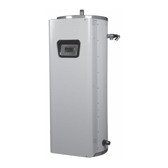
Service Handbook
commercial electric Water HeaterS
modelS cSb52**i, cSb82**i, cSb120**i
& cSb52**S, cSb82**S, cSb120**S
inStallation conSiderationS - pre Service
cHecKS - Water Heater conStruction -
500 Tennessee Waltz Parkway
operation & Service - troubleSHooting
Ashland City, TN 37015
Servicing SHould only be performed by a Qualified Service agent.
PRINTED IN THE U.S.A 1008
315015-000
1
Advertisement

Related Manuals for State Water Heaters CSB52 I Series


Summary of Contents for State Water Heaters CSB52 I Series
- Page 1 http://waterheatertimer.org/3-phase-water-heater.html Service Handbook commercial electric Water HeaterS modelS cSb52**i, cSb82**i, cSb120**i & cSb52**S, cSb82**S, cSb120**S inStallation conSiderationS - pre Service cHecKS - Water Heater conStruction - 500 Tennessee Waltz Parkway operation & Service - troubleSHooting Ashland City, TN 37015 Servicing SHould only be performed by a Qualified Service agent. PRINTED IN THE U.S.A 1008 315015-000...
- Page 3 COMMERCIAL ELECTRIC WATER HEATER SERVICE MANUAL TABLE OF CONTENTS INTRODUCTION ............... 2 ELECTRONIC CONTROLS............. 41 Qualifications ..............2 CCB - Central Control Board ..........42 Service Warning ..............2 CCB Socket & Wiring Terminal Identification .... 43 Tools Required..............3 CCB Enable Disable Circuit(s) Test......
- Page 4 INTRODUCTION INTRODUCTION This Service Manual is designed to be an aid in servicing and troubleshooting the commercial electric water heater models listed on the cover.The instructions, illustrations and procedures contained in this manual are used to verify proper operation and to diagnose and repair common service problems.
- Page 5 INTRODUCTION INSTRUCTION MANUAL Have a copy of the Instruction Manual that came with the water heater on hand for the correct model water heater you are working with before servicing. Installation information given in this Service Manual IS NOT a complete installation instruction.
- Page 6 INSTALLATION CONSIDERATIONS INSTALLATION CONSIDERATIONS Installation information given in this Service Manual IS NOT a complete installation instruction. Installation information covered in this Service Manual has a limited focus as it applies to servicing. This Service Manual does not replace or supersede the Instruction Manual that came with the water heater.
- Page 7 INSTALLATION CONSIDERATIONS ELECTRICAL REQUIREMENTS Grounding Review the electrical ground requirements given in the Instruction Manual that came with the water heater and ensure the water heater has been properly grounded. The water heater must be grounded in accordance with the National Electric Code and/or local codes.
- Page 8 PRE SERVICE CHECKS PRE SERVICE CHECKS WIRING CONNECTIONS With the power supply to the water heater turned off ensure the wiring connections are properly tightened to all components including: high voltage terminal blocks, fuse blocks, contactors, transformers and heating elements. Loose connections at any connection point will cause increased amperage and excessive heat which can damage wiring and components.
- Page 9 WATER HEATER CONSTRUCTION WATER HEATER CONSTRUCTION There are two types of commercial electric water heaters covered in this manual. See Figure 1 on page 8 and Figure 2 on page 9. SURFACE MOUNT CONTROL MODELS The first type of water heater covered in this manual is equipped with surface mount thermostat/ECO controls - Surface Mount Control Models.
- Page 10 WATER HEATER CONSTRUCTION SURFACE MOUNT CONTROL MODELS Figure 1 Servicing should only be performed by a Qualified Service Agent...
- Page 11 WATER HEATER CONSTRUCTION ELECTRONIC CONTROL MODELS Figure 2 Servicing should only be performed by a Qualified Service Agent...
- Page 12 OPERATION & SERVICE OPERATION & SERVICE This section of the manual will cover the principles of electricity, single and three phase power, fuses, surface mount thermostat/ECO combination controls, heating element construction & operation, heating element sensors, contactors, common service procedures and more.
- Page 13 OPERATION & SERVICE Ohms Law A law that explains the relationship between voltage, current and resistance. The law states that the electric current flowing through a conductor is equal to the voltage divided by the resistance. The following equations further explain ohms law. Ohms Law applied to “SINGLE PHASE”...
- Page 14 OPERATION & SERVICE SINGLE AND THREE PHASE POWER The water heaters covered in this manual can be field converted for a single or three phase power supply - see pages 15 and 16. These water heaters can be factory ordered for standard North American power supplies;...
- Page 15 OPERATION & SERVICE Checking Single Phase (1Ø) Power A single phase power supply consists of two wires connected to the L1 and L2 terminals of the Power Distribution Block, the L3 terminal is not used. On a single phase (1Ø) 277 volt power supply one of the two wires is a “neutral”...
- Page 16 OPERATION & SERVICE Checking Three Phase (3Ø) Power A three phase power supply consists of three wires connected to the L1, L2 and L3 terminals of the Power Distribution Block. All three wires are “hot” with voltage present. Voltage Between Terminals: Set the volt meter to an AC voltage range above the expected voltage (600 VAC or higher range initially).
- Page 17 OPERATION & SERVICE PHASE CONVERSIONS - SURFACE MOUNT CONTROL MODELS Internal wiring connections between the Power Distribution Block and the heating elements are different on Surface Mount Control (see Figure 1 page 8) and Electronic Control (see Figure 2 page 9) model water heaters. Because of these differences there are two methods for field converting these models to work with single and three phase power supplies.
- Page 18 OPERATION & SERVICE PHASE CONVERSIONS - ELECTRONIC CONTROL MODELS Internal wiring connections between the Power Distribution Block and the heating elements is different on Surface Mount Control (see Figure 1 page 8) and Electronic Control (see Figure 2 page 9) model water heaters. Because of these differences there are two methods for field converting these models to work with single and three phase power supplies.
- Page 19 OPERATION & SERVICE FUSES The water heaters covered in this manual have power circuit fuses to protect the heating element circuits. Electronic Control models will have two additional fuses to protect the primary winding of the 120 Volt Control Circuit Transformer. See Figures 1 and 2 on pages 8 and 9 for location.
- Page 20 OPERATION & SERVICE SURFACE MOUNT THERMOSTATS The Surface Mount Control Model water heaters covered in this manual have “separate” thermostat/ECO (energy cut out) combination controls mounted to the surface of the storage tank directly above the heating elements they control. IE: a water heater equipped with 9 heating elements will have 9 thermostat/ECO controls.
- Page 21 OPERATION & SERVICE Thermostat & ECO Test Secure power to the water heater at the main breaker or disconnect switch. Ensure tank temperature is less than 100°F/38°C - dump water to lower tank temperature if necessary. Press the red reset button firmly on all thermostat/ECO controls. Raise the temperature setting on all thermostat/ECO controls to 140°F or higher.
- Page 22 OPERATION & SERVICE HEATING ELEMENTS This section of the manual provides information on how to determine the actual voltage and wattage rating of a heating element along with tables showing heating element configurations, heating element amperage and heating element resistance/ohms. This section also contains heating element test procedures to measure;...
- Page 23 OPERATION & SERVICE Heating Element Ratings Heating elements are labeled with their voltage and KW rating - see image below. The element shown here is a 6000 watt (6 KW) 240 volt element. Wattage and Voltage Ratings Note: some heating elements are dual rated elements IE: 208/240 volts Heating Element Configurations...
- Page 24 OPERATION & SERVICE Heating Element Amperage This table shows the approximate amp draw for the various heating elements used. First determine the actual rated wattage and voltage of the element being tested - see Heating Element Ratings on page 21. Then follow the Heating Element Amperage Test procedure on page 23 to measure amperage at each heating element.
- Page 25 OPERATION & SERVICE Heating Element Amperage Test This test should be considered as a first diagnostic procedure for the common service complaints of no hot water or not enough hot water. The heating element amperage test shown on this page is the best procedure to quickly determine which (if any) heating elements are not working properly.
- Page 26 OPERATION & SERVICE Heating Element Voltage Test This test is typically performed after an amperage test (see page 23) has determined one or more heating elements is not drawing correct amperage. Secure power to the water heater at the main breaker or disconnect switch. Ensure tank temperature is less than 100°F/38°C - dump water to lower tank temperature if necessary.
- Page 27 OPERATION & SERVICE Heating Element Resistance & Ground Tests This is a two part test. In the first part of this test the actual resistance (ohms) of each heating element is measured. In the second part of this test each heating element is tested for any continuity to ground to ensure the heating element is not shorted to ground.
- Page 28 OPERATION & SERVICE Heating Element Ground Test Secure power to the water heater at the main breaker or disconnect switch. Verify with an AC volt meter that there is not any voltage present at the Power Distribution Block (see Figures 1 and 2 on pages 8 and 9) and at the two wiring terminals on the ends of all heating elements. Disconnect both power wires from the terminals on the top of all heating elements to be tested.
- Page 29 OPERATION & SERVICE ELEMENT SENSORS Electronic Control Models covered in this manual monitor all heating elements using Element Sensors. Each Element Sensor monitors 3 heating elements. There will be one Element Sensor for each Bank of heating elements. See Figure 2 on page 9 and the illustration on page 30.
- Page 30 OPERATION & SERVICE Element Sensor Operation When current (amperage) flows through a wire in an electrical circuit a magnetic field is developed that radiates out from the wire. The individual current sensors detect this magnetic field. When current flows in a wire routed through the hole in one of the individual current sensors, the sensor is activated and sends a signal back to the CCB confirming the presence of current.
- Page 31 OPERATION & SERVICE CONTACTORS This section of the manual provides information on how contactors used on Electronic Control Models are constructed, how they work and how to test contactor operation - see Figure 2 on page 9 for location of the contactors on these models. Surface Mount Control Models are not equipped with contactors.
- Page 32 OPERATION & SERVICE Contactor Configurations This illustration shows how contactors are configured and how they provide power to the heating elements on Electronic Control Model water heaters, This is a redundant contactor configuration - two contactors must close their contacts to energize any heating element. Elements and Banks are numbered according to how the control system monitors them - see Element Sensors pages 27 and 28.
- Page 33 OPERATION & SERVICE Contactor Inspection A thorough visual inspection of the contactors used on Electronic Control Models should be performed as part of any regular maintenance program and whenever the water heater is being serviced. Refer to the listed Steps and images below for this procedure. Secure power to the water heater at the main breaker or disconnect switch.
- Page 34 OPERATION & SERVICE Contactor Coil Voltage - At Contactor This test procedure will measure contactor coil voltage at the contactor. Ensure tank temperature is less than 100°F/38°C - dump water to lower tank temperature if necessary. Adjust the temperature settings to ensure a call heat is active for all heating elements. Raise the Operating Set Point in the Temperatures Menu to 140°F or higher.
- Page 35 OPERATION & SERVICE Contactor Coil Voltage - At CCB This test procedure will measure contactor coil voltage where it originates at the J4 wiring terminals on the CCB. See page 42 for the CCB’s J4 wiring terminal location. Ensure tank temperature is less than 100°F/38°C - dump water to lower tank temperature if necessary. Adjust the temperature settings to ensure a call heat is active for all heating elements.
- Page 36 OPERATION & SERVICE TRANSFORMERS This section of the manual provides information on how to test and ensure the multiple tap 120 VAC Control Circuit Transformer is wired properly on Electronic Control Models. This section will also provide test procedures for the 24 VAC transformer used by the electronic control system - see Figure 2 on page 9 for location of the transformers on these models.
- Page 37 OPERATION & SERVICE 120 VAC Control Circuit Transformer Test Ensure the main breaker or disconnect switch is turned on. Verify with an AC volt meter that proper voltage is present at the Power Distribution Block (see Figure 2 on page 9 and pages 12 - 14). Check Primary Winding Voltage: Using an AC volt meter;...
- Page 38 OPERATION & SERVICE 24 VAC Transformer Test Ensure the main breaker or disconnect switch is turned on. Verify with an AC volt meter that proper voltage is present at the Power Distribution Block (see Figure 2 on page 9 and pages 12-14). Check Primary Winding Voltage: Using an AC volt meter;...
- Page 39 OPERATION & SERVICE IMMERSION TEMPERATURE PROBE This section of the manual provides Immersion Temperature Probe information on how test the Immersion Temperature Probe on Electronic Control Models - see Figure 2 on page 9 for location. The Immersion Temperature Probe contains the ECO (energy cut out) and a Temperature Sensor.
- Page 40 OPERATION & SERVICE Temperature Sensor Resistance Test Secure power to the water heater at the main breaker or disconnect switch. Unplug the J5 plug from the CCB circuit board - see page 42 for location. Using an ohm meter: set the ohm meter range to a scale above 30,000 ohms initially. Touch the ohm meter probes between the two middle pins (black wires) of the J5 plug end as shown in the image below.
- Page 41 OPERATION & SERVICE Temperature Sensor DC Voltage Test Ensure the main breaker or disconnect switch is turned on. Verify the CCB circuit board has the correct input voltage at the J2 socket and is properly grounded - perform the “Checking Power and Ground To The CCB” tests on page 46. Unplug the J5 plug from the CCB circuit board (note: the control system will lock out and display “Temp Probe Open”...
- Page 42 OPERATION & SERVICE ECO Voltage Test Ensure the main breaker or disconnect switch is turned on. Verify the CCB has the correct input voltage at the J2 socket and is properly grounded - perform the Checking Power and Ground To The CCB tests on page 46. Using an AC volt meter;...
- Page 43 ELECTRONIC CONTROLS ELECTRONIC CONTROLS This section covers the electronic control system used on Electronic Control Models - see Figure 1 on page 9. The control system includes a CCB (Central Control Board) and a UIM (User Interface Module). The CCB constantly monitors safely controls, heating elements, water temperature and other functions of the water heater.
- Page 44 ELECTRONIC CONTROLS CCB - CENTRAL CONTROL BOARD All wiring connections and sockets will be identified in the following pages. The Troubleshooting section of this manual will refer to this illustration and information. Servicing should only be performed by a Qualified Service Agent...
- Page 45 ELECTRONIC CONTROLS CCB Socket & Wiring Terminal Identification Refer to the illustration on page 42 for physical location of the sockets and wiring terminals. J1 Socket - Transformer PIN # DESCRIPTION 120 VAC hot to transformer Not used 120 VAC neutral to transformer 24 VAC out from transformer 24 VAC out from transformer J2 Socket - 120 VAC Power Supply...
- Page 46 ELECTRONIC CONTROLS J7 Socket - Enable / Disable Circuits 1 & 2 (see pages 45 & 54) PIN # DESCRIPTION Enable/Disable circuit 1 Enable/Disable circuit 1 Enable/Disable circuit 2 Enable/Disable circuit 2 J9 Socket - Not Used J10 Socket - Not Used J11 Port - Communication Port - UIM Display (user interface module) J12 Socket - Heating Element Sensors Bank 1 J13 Socket - Heating Element Sensors Bank 2...
- Page 47 ELECTRONIC CONTROLS CCB Enable/Disable Circuit(s) Test The electronic control system includes two enable/disable circuits (see page 54) for use with field installed supervisory controls such as building EMS (Energy Management System). These two circuits are located at the CCB’s four pin J7 Socket. Both of these Enable/Disable circuits must be closed to enable heating operation.
- Page 48 ELECTRONIC CONTROLS Checking Power and Ground To The CCB The CCB circuit board is powered by the120 VAC Control Circuit Transformer (see pages 34-35) at the J2 Socket, pins 1 & 3 (see page 42). This procedure is performed to ensure the 120 VAC power is being supplied to the CCB.
- Page 49 ELECTRONIC CONTROLS UIM - USER INTERFACE MODULE UIM Components The UIM’s major components include a Circuit Board with LCD display and a Button Pad Overlay which contains the five user input buttons. Service Notes - Button Pad Ribbon Cable The Ribbon Cable that connects the Button Pad Overlay to the UIM Circuit Board must be plugged in exactly as shown in the images below;...
- Page 50 ELECTRONIC CONTROL SYSTEM ELECTRONIC CONTROL SYSTEM CONTROL SYSTEM FEATURES Advanced Diagnostics: Plain English text and animated icons display detailed operational and diagnostic information. LCD screen on the front of the water heater displays the Sequence of Operation in real time. Fault or Alert messages are displayed when operational problems occur.
- Page 51 ELECTRONIC CONTROL SYSTEM THE DESKTOP SCREEN The illustration below shows the control system “Desktop Screen.” This is the default screen. If there are no active Fault or Alert conditions and no user input for approximately 10 minutes the control system will return to this screen automatically. Model Information: Model information and menu titles are shown in the black bar at the top of the Desktop Screen.
- Page 52 ELECTRONIC CONTROL SYSTEM Table 1 Status Icons ICON DESCRIPTION Water temperature in the tank has fallen. Shaded area of the animated thermometer icon will rise and fall in response to water temperature in the storage tank as sensed from the immersion Temperature Probe.
- Page 53 ELECTRONIC CONTROL SYSTEM Table 2 - Operating States STATE DESCRIPTION Standby The water heater is not in an active heating cycle. This usually indicates the temperature in the tank has reached the Operating Set Point and the control system has terminated the heating cycle. Heating The control system is in the Heating Mode.
- Page 54 ELECTRONIC CONTROL SYSTEM TEMPERATURES MENU Operating Set Point User adjustable setting 90°F to 190°F range; factory default is 120°F. When the water temperature sensed by the control system from the immersion Temperature Probe reaches the Operating Set Point the control system will end the heating cycle.
- Page 55 ELECTRONIC CONTROL SYSTEM Temperature Settings The Operating Set Point and the Differential Settings are adjusted in the Temperatures Menu. The following instructions explain how to adjust these user settings and navigate the control system menus. ACTION DISPLAY From the Desktop Screen, press the Operational Button underneath “MENU”...
- Page 56 ELECTRONIC CONTROL SYSTEM HEATER STATUS MENU This menu displays non adjustable operational information. This menu contains more information that can be displayed on one screen of the LCD display. Use the Up & Down Buttons to navigate to the bottom of this menu. Status Top Of Menu Displays the current Operating State of the...
- Page 57 ELECTRONIC CONTROL SYSTEM ECONOMY MODE SETUP MENU This menu contains settings used to establish an “Economy Set Point” and “Economy Mode” operating periods. This control system feature can help reduce operating costs during unoccupied, low load, or peak demand periods. Setpoint Adjustment Desktop Screen During Economy Mode Adjustable user setting (2°F to 50°F - factory...
- Page 58 ELECTRONIC CONTROL SYSTEM Economy Mode Settings Setpoint Adjustment Value ACTION DISPLAY From the Desktop screen, press the Operational Button underneath “MENU” to enter the Main Menu. (see UIM Navigation on page 48) Notice how the text above the Operational Buttons on the display changes as you navigate through the various menus and screens.
- Page 59 ELECTRONIC CONTROL SYSTEM Economy Mode Settings Time Clock Settings ACTION DISPLAY From the Desktop Screen navigate to the Economy Mode Setup menu - see page 56 for instructions. Use the Up/Down buttons to select (highlight in black) Current Time sub menu. Press the Operational Button underneath “CHANGE”...
- Page 60 ELECTRONIC CONTROL SYSTEM Economy Mode Settings Daily Operating Mode Settings ACTION DISPLAY Economy Mode All Day: From the Economy Mode Setup menu use the Up/Down buttons to select (highlight in black) the Daily sub menu for “Sun.” Press the Operational Button underneath “CHANGE”...
- Page 61 ELECTRONIC CONTROL SYSTEM ALARM OUTPUT SETUP MENU Permits user to set the condition (from a list of options) for when the CCB’s integral alarm output relay will be energized. Alarm relay connections (common, normally open, normally closed) are located on the J3 terminal strip on the CCB (see page 42). Alarm output relay contacts are capable of switching 1 amp maximum at 120 VAC.
- Page 62 ELECTRONIC CONTROL SYSTEM DISPLAY SETTINGS MENU Permits user to set display options for viewing information on the UIM’s LCD screen. Temperature Units Adjustable user setting that changes temperature units display to Celsius °C or Fahrenheit °F. Backlight Delay Adjustable user setting that determines how long the UIM’s LCD backlight remains illuminated after a key has been pressed.
- Page 63 ELECTRONIC CONTROL SYSTEM HEATER INFORMATION MENU This menu displays non adjustable operational information. Elapsed Time Top Of Menu Total accumulated time the control system (water heater) has been energized. Total Heating Time Total accumulated time the control system has been in the heating mode. IE: any heating elements have been energized.
- Page 64 ELECTRONIC CONTROL SYSTEM CURRENT FAULT / ALERT MENU This menu displays non adjustable Main Menu - Current Fault Selected operational information. With the Fault History sub menu selected in Main Menu; press the Operational Button underneath “SELECT” to display the current Fault or Alert message. If there is not a Fault or Alert condition currently active “(none)”...
- Page 65 RESTORE FACTORY DEFAULTS MENU This control system menu allows the user to restore most of the control system’s user settings to their factory default settings. User settings in the Alarm Output Setup and Display Settings menus are unaffected by executing Restore Factory Defaults. Restore Factory Defaults ACTION DISPLAY...
- Page 66 TROUBLESHOOTING TROUBLESHOOTING COMMON SERVICE PROBLEMS No Hot Water Hot water supply valve turned off. Check power to the water heater - see pages 12 - 14. Check thermostat/ECO controls on Surface Mount Control Models - see pages 18 & 19. Check Operating Set Point and Differential Set Points on Electronic Control Models - see pages 52 &...
- Page 67 TROUBLESHOOTING ELECTRONIC CONTROL MODELS The remainder of the Troubleshooting section covers Electronic Control Models only. Fault Conditions When the control system declares a Fault condition it will display a Fault message on the UIM and lock out. Voltage to the contactor coils and heating elements is terminated to prevent further heating operation.
- Page 68 TROUBLESHOOTING Control System Unresponsive (cont) DISPLAYED MESSAGE CHECK/REPAIR CONDITION/INDICATES • Ensure Ribbon Cable from the Button overlay is UIM is Inoperable inserted correctly in UIM J3 Socket (page 47). UIM does not respond to any user input using the • Call the technical support phone number on the operational and/or Up and Down buttons.
- Page 69 TROUBLESHOOTING FAULT AND ALERT MESSAGES Troubleshooting procedures for the most common Fault and Alert messages are covered in this section. In the tables that follow the first column shows the Fault or Alert message as displayed by the UIM along with an explanation. The second column details things to check or repair and references test procedures detailed in the Operation and Service section (pages 10 - 47) of this manual.
- Page 70 TROUBLESHOOTING Fault & Alert Messages DISPLAYED MESSAGE CHECK/REPAIR CONDITION/INDICATES • Check the J5 plug/socket connections at the “Temp Probe Open” CCB ensure they are mating properly and pro- (Fault Condition) viding good contact. Check the pins inside the J5 plug/socket for wear or damage. See CCB The control system has detected an open circuit in illustration and socket identification on pages 42 the temperature sensor.
- Page 71 TROUBLESHOOTING Fault & Alert Messages DISPLAYED MESSAGE CHECK/REPAIR CONDITION/INDICATES • Check the J5 plug/socket connections at the “Energy Cut Out (ECO)” CCB ensure they are mating properly and pro- (Fault Condition) viding good contact. Check the pins inside the J5 plug/socket for wear or damage. See CCB The control system has detected excessive water illustration and socket identification on pages 42 temperature inside the water heater.
- Page 72 NOTES...
- Page 73 NOTES...
- Page 74 NOTES...
- Page 76 500 Tennessee Waltz Parkway, Ashland City, TN 37015 Technical Support and Parts: 800-365-0577 www.statewaterheaters.com...