
Summary of Contents for Immergas 3.030908
- Page 1 COD. 3.030908 Concentrator kit with Instruction and wireless room probe warning book...
-
Page 2: Preliminary Remarks
The material must be stored in a dry place protected from the weather. This instruction manual provides technical information for installing the Immergas kit. As for the other issues related to kit installation (e.g. safety in the workplace, environmental protection, accident prevention), it is necessary to comply with the provisions specified in the regulations in force and with the principles of good practice. -
Page 3: Package Contents
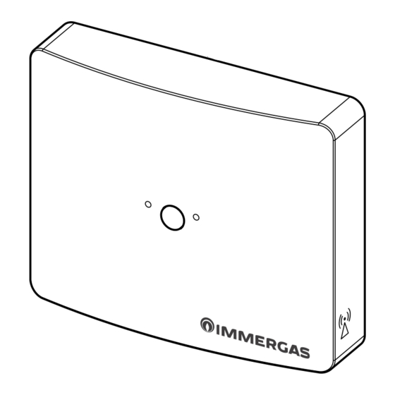
The manufacturer will not be held responsible in the following cases: • Incorrect installation. Malfunctions of the boiler to which the kit is applied. Unauthorised changes or tampering. Total or partial failure to comply with instructions. Exceptional events etc. INSTALLATION. 1.1 INSTALLATION RECOMMENDATIONS. - Page 4 1.3 MAIN DIMENSIONS OF CONCENTRATOR. Fig. 2 29 mm 105 mm 1.4 MAIN DIMENSIONS OF WIRELESS ROOM PROBE. Fig. 3 29 mm 105 mm...
- Page 5 1.5 INSTALLATION OPERATIONS OF WIRELESS ROOM PROBE AND CONCENTRATOR. N.B.: the support for wall installation is the same both for fixing the wireless room probe and the concentrator. Concentrator fastening: 1) Separate the fixing support from the cover of the Concentrator by prying with a screwdriver in the appropriate recess. Manually pull the cover outwards to separate it from the support (Fig.
- Page 6 N.B.: the use in electromagnetically non-critical places and in structures made of non-metallic or shielding materials is recommended. During installation, take the necessary precautions as indicated in fig. 7. Fig. 7 3) Do not operate with the boiler powered on to perform electrical connec-tions of the concentrator. The connection must be made as indicated on the wiring diagram shown on this instruction leaflet.
- Page 7 Wireless room probe fixing: 1) Separate the fixing support from the cover of the wireless room probe by prying with a screwdriver in the appropriate recess. Manually pull the cover outwards to separate it from the support (Fig. 9). N.B.: the probe can be fixed to its support after the "association" operations. This makes the association procedure easier, with no need to move around the house.
- Page 8 3) Secure the cover of the wireless room probe to the support by engaging it by pressure (Fig. 13). N.B.: when closing the cover, make sure it is correctly aligned with the fixing support. N.B.: in order to secure the probe to the support correctly, the batteries must be positioned in the lower part of the support. Fig.
- Page 9 COMBINATION OF BOILER WITH WIRELESS ROOM PROBES. After the electrical connection of the concentrator to the boiler, it is recom-mended to follow the steps below. 2.1 ZONE ASSIGNMENT TO WIRELESS ROOM PROBE Verification of any association previously activated on the wireless probe Insert the batteries on the probe and press for 5 sec.
- Page 10 2.3 ASSIGNMENT OF FURTHER ZONES TO AS MANY WIRELESS ROOM PROBES THROUGH A SINGLE CONCENTRATOR. Only after activating the communication (and possible setting) of zone actuator boards such as relay interface board or zone board (present on DIM ERP), the display board offers the possibility to activate room control on zone 2 and zone 3 on the menu zone via wireless room probes.
- Page 11 2.6 ERRORS OR FAULTS SHOWN ON THE DISPLAY The boiler display, under each zone identification "house", indicates the tem-perature read by the wireless probe assigned to the zone. In the event of a fault, the display signals an error code under each zone identification "house" as illustrated in the table below: Error Description Possible remedy...
- Page 12 It can take up to 10 minutes to reset the error signal (after resolution). It is advisable to "force" the communication between the probe and concentrator by briefly pressing the button on the probe; in this way the RF communica-tion between the two devices will be accelerated and the error signal will be cancelled in a short time.
- Page 13 2.8 MAIN SIGNALS THROUGH WIRELESS PROBE LEDS On the wireless probe there are two LEDs (1-3) next to the button (2) (Fig. 16). The possible signals on these LEDs are the following. Status Condition LH LED RH LED Normal operation Normal operation 1 flash each 60 seconds No association...
- Page 14 2.9 GENERAL REMARKS ON BOILER OPERATION WITH WIRELESS ROOM PROBES The wireless room probe (with concentrator) allows the measurement of the room temperature and the sending of this value to the boiler control panel, where it is possible to set a weekly program for room temperature control through the display board. There is no manual command or adjustment (available to the user) of the room control on the probe.
-
Page 15: Special Functions
2.10 SPECIAL FUNCTIONS The settings available on room control via wireless probes are accessible in the Zone menu with Service access (See boiler instructions). Enable room probe (default = YES): as a factory setting, after assigning the wireless probe to the zone, room control settings are possible (with Comfort set, reduced set and manual set). -
Page 16: Cleaning The Cover
2.12 OPERATION IN FAULT CONDITIONS Radio communication failure between room probe and concentrator: Failure in receiving data from the wireless probe causes the relative error to appear on the display; typically the error is signalled after 4 minutes, keeping the last reading on the room probe active with consequent heating function as previously running. -
Page 17: Technical Specifications
TECHNICAL SPECIFICATIONS. Concentrator: • Dimensions (LxAxP): ............105 x 86 x 23 (mm) • Basic power supply: ......24 V DC via Communication BUS M3 • Maximum absorption: ............20 mA - 500 mW. • RF communication: .... carrier 868.4 MHz, GFSK modulation, coverage 30-100 m (depending on the environment) •... -
Page 18: Wiring Diagram
WIRING DIAGRAM. CONNECTION DIAGRAM OF THE CONCENTRATOR TO THE BOILER TERMINAL BLOCK Key: Colour code key: 1 - Wireless Concentrator BK - Black 2 - Dominus (optional) BL - Blue 3 - External probe (optional) BR - Brown 4 - System delivery probe (optional) G - Green 5 - Low voltage connection terminal block GY - Grey... - Page 20 NOTE: correct periodic maintenance is highly recommended. Seguici su Immergas Italia Follow us on Immergas Italia Immergas TOOLBOX L’App studiata da Immergas per i professionisti The App designed by Immergas for professionals Disponibile su Disponibile su Disponibile su immergas.com...