
Related Manuals for HP ProBook 450 G10


Summary of Contents for HP ProBook 450 G10
- Page 1 Maintenance and Service Guide SUMMARY This guide provides maintenance information about such topics as spare parts, removal and replacement of parts, security, and backing up.
- Page 2 HP Inc. to be bound by the terms of the HP End Not all features are available in all under license. Intel, Core, and Thunderbolt User License Agreement (EULA).
- Page 3 Safety warning notice Reduce the possibility of heat-related injuries or of overheating the computer by following the practices described. WARNING! To reduce the possibility of heat-related injuries or of overheating the computer, do not place the computer directly on your lap or obstruct the computer air vents. Use the computer only on a hard, flat surface.
- Page 4 Important notice about Customer Self-Repair parts Your computer includes Customer Self-Repair parts and parts that should be accessed by only an authorized service provider. IMPORTANT: See "Removal and replacement procedures for Customer Self-Repair parts" for details. Accessing parts described in "Removal and replacement procedures for authorized service provider parts"...
-
Page 5: Table Of Contents
Table of contents 1 Product description............................................. 1 2 Components................................................5 Right..................................................5 Left....................................................7 Display ...................................................7 Low blue light mode (select products only)..............................7 Keyboard area..............................................9 Touchpad ..............................................9 Touchpad settings ......................................... 9 Adjusting touchpad settings................................9 Turning on the touchpad ..................................9 Touchpad components ...................................... - Page 6 7 Backing up, restoring, and recovering....................................69 Backing up information and creating recovery media...........................69 Using Windows tools for backing up.................................69 Using the HP Cloud Recovery Download Tool to create recovery media (select products only)......69 Restoring and recovering your system..................................69 Creating a system restore .......................................70 Restoring and recovery methods ..................................70...
- Page 7 Accessing HP PC Hardware Diagnostics Windows..........................76 Accessing HP PC Hardware Diagnostics Windows from HP Support Assistant..........76 Accessing HP PC Hardware Diagnostics Windows from the Start menu (select products only).....77 Downloading HP PC Hardware Diagnostics Windows.........................77 Downloading the latest HP PC Hardware Diagnostics Windows version from HP..........77 Downloading the HP PC Hardware Diagnostics Windows from the Microsoft Store........77...
- Page 8 12 Power cord set requirements........................................90 Requirements for all countries ......................................90 Requirements for specific countries and regions.............................90 13 Recycling................................................92 Index....................................................93 viii...
-
Page 9: Product Description
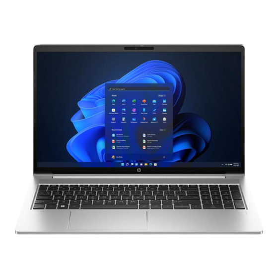
Product components and their descriptions Category Description Product Name HP ProBook 450 15.6 inch G10 Notebook PC Processors Intel® processors Intel®Core® i7 1360P processor (5.0 GHz, 12 cores, 18 MB Intel Smart Cache, 28 W) Intel Core i5 1340P processor (4.6 GHz, 12 cores, 12 MB Intel Smart Cache, 28 W) Intel Core i7-1355U processor (1.7 GHz, 10 cores, 12 MB Intel Smart Cache, 15 W) - Page 10 Table 1-1 Product components and their descriptions (continued) Category Description Memory Two customer-accessible (by IT or self-maintainers only) memory module slots supporting up to 32 GB of RAM DDR4-3200 dual-channel support Supports the following configurations: ● 32 GB (16 × 2) ●...
- Page 11 Compatible with Miracast® devices Two WLAN antennas Supports HP Connection Optimizer Supports HP Extended Range Wireless LAN Wireless Wide Area Network (WWAN) (select products only) Intel XMM 7560 R + LTE-Advanced Pro WWAN (Cat 16) Two antennas integrated at top of display...
- Page 12 Windows 11 Pro Education Windows 11 Home - HP recommends Windows 11 Pro for Business Windows 11 Home Single Language - HP recommends Windows 11 Pro for Business Windows 11 Pro (Windows 11 Enterprise or Windows 10 Enterprise available with a Volume Licensing...
-
Page 13: Components
For additional safety information, see the Regulatory, Safety, and Environmental Notices . To access this guide: ■ Select the Search icon in the taskbar, type HP Documentation in the search box, and then select HP Documentation. NOTE: When a device is connected to the jack, the computer speakers are disabled. - Page 14 Table 2-1 Right-side components and their descriptions (continued) Component Description USB SuperSpeed 5 Gbps port Connects a USB device, provides high-speed data transfer, and (for select products) charges small devices (such as a smartphone) when the computer is on or in Sleep mode. NOTE: Use a standard USB Type-A charging cable or cable adapter (purchased separately) when charging a small...
-
Page 15: Left
To reduce the risk of serious injury, read the workstation setup and proper posture, health, and work habits for computer users. The Safety & Comfort Guide also provides important electrical and mechanical safety information. The Safety & Comfort Guide is available on the web at http://www.hp.com/ergo. Left... - Page 16 Regulatory, Safety, and Environmental Notices that applies to your For wireless regulatory notices, see the section of the country or region. To access this guide: ■ Select the Search icon in the taskbar, type HP Documentation in the search box, and then select HP Documentation. Chapter 2 Components...
-
Page 17: Keyboard Area
Keyboard area Keyboards can vary by language. NOTE: The keyboard, including the function keys and power key (select products only), is disabled in stand, tent, and tablet modes. To enable the keyboard, including the power key, change to the clamshell mode. -
Page 18: Lights
Table 2-4 Touchpad components and their descriptions Component Description Touchpad zone Reads your finger gestures to move the pointer or activate items on the screen. Left control zone Textured area that allows you to perform additional gestures. Right control zone Textured area that allows you to perform additional gestures. - Page 19 Table 2-5 Lights and their descriptions Component Description Caps lock light On: Caps lock is on, which switches the key input to all capital letters. Privacy key light On: Privacy screen is on, which helps prevent side-angle viewing. Mute light ●...
-
Page 20: Button, Speakers, And Fingerprint Reader
Button, speakers, and fingerprint reader Fingerprint readers can be located on the touchpad, on a side panel of the computer, or on the top cover below the keyboard. IMPORTANT: To verify that your computer supports fingerprint reader sign-in, select the Search icon in the taskbar, type Sign-in options in the search box, and then select the Sign-on options app. -
Page 21: Special Keys
Table 2-6 Button, speakers, and fingerprint reader and their descriptions (continued) Component Description Power button ● When the computer is off, press the button briefly to turn on the computer. When the computer is on, press the button briefly to ●... - Page 22 Table 2-7 Special keys and their descriptions Component Description Displays system information when pressed in combination with the key. Executes frequently used system functions when pressed in combination with another key. Such key combinations are called hot keys . Windows key Opens the Start menu.
-
Page 23: Bottom
Bottom Use the illustration and table to identify the bottom components. Table 2-8 Bottom component and description Component Description Vent Enables airflow to cool internal components. NOTE: The computer fan starts up automatically to cool internal components and prevent overheating. It is normal for the internal fan to cycle on and off during routine operation. -
Page 24: Labels
Your service label will resemble one of the examples shown below. Refer to the illustration that most closely matches the service label on your computer. Table 2-10 Service label components Component Serial number Product ID HP product name Table 2-11 Service label components Component HP product name Product ID Serial number... -
Page 25: Using A Sim Card (Select Products Only)
Before purchasing a SIM card, follow these instructions to determine the correct SIM card size for your computer. Go to http://www.hp.com/support, and then search for your computer by product name or number. Select Product Information. Refer to the listed options to determine which card to purchase. - Page 26 NOTE: Your SIM card slot may have an icon to show which way the card should be inserted into the computer. To remove the SIM card, press in gently on the card to disengage the SIM lock, and then remove it from the slot.
-
Page 27: Illustrated Parts Catalog
To identify the computer major components, use this illustration and table. NOTE: HP continually improves and changes product parts. For complete and current information about supported parts for your computer, go to http://partsurfer.hp.com, select your country or region, and then follow the on-screen instructions. NOTE: Details about your computer, including model, serial number, product key, and length of warranty, are on the service tag at the bottom of your computer. - Page 28 Table 3-1 Computer major component descriptions and part numbers Item Component Spare part number Display assembly not available as a spare part NOTE: Display spare parts are available only as subcomponents. For spare part information, Display assembly subcomponents on page Top cover with keyboard NOTE: For a detailed list of country codes, see...
- Page 29 Table 3-1 Computer major component descriptions and part numbers (continued) Item Component Spare part number (10) I/O board N01502-001 NOTE: The I/O board cables are available in the Cable Kit as spare part number N03218-001. The RJ-45 door is available as spare part number M21994-001. (11) Battery 3 cell, 51 Whr...
-
Page 30: Display Assembly Subcomponents
Display assembly subcomponents To identify the display assembly subcomponents, use this illustration and table. Table 3-2 Display component descriptions and part numbers Item Component Spare part number Display bezel For use in models with an FHD display and without a camera M21991-001 For use in models with an FHD display and with a 5 MP camera M21992-001... -
Page 31: Cable Kit
Table 3-2 Display component descriptions and part numbers (continued) Item Component Spare part number Camera module HD camera N05869-001 5 MP + IR camera N50613-001 Microphone module N05863-001 Display panel (includes cover and bezel adhesive) NOTE: Display panel tape is available as spare part number N00351-001. QHD, 300 nits N44345-001 FHD, 400 nits... -
Page 32: Miscellaneous Parts
L72056-001 USB-C-to-USB-A hub 916838-001 HP Universal USB-C Multiport Hub M96882-001 WLAN protective tape N02047-001 Screw Kit (for use with HP USB-C Dock G5) L64089-001 Screw Kit (for use in product component removal and replacement) N01913-001 Chapter 3 Illustrated parts catalog... - Page 33 Cable kit for use with Thunderbolt 120 W G4 dock M88058-001 Cable kit for use with Thunderbolt 280 W G4 dock M88059-001 HP Prelude Pro 15.6 top load case M03618-001 HP Prelude Pro 15.6 backpack M03617-001 Power cord (C13, premium, 1.0 m [3.3 ft])
- Page 34 Table 3-4 Miscellaneous part descriptions and part numbers (continued) Component Spare part number South Korea N24675-001 Switzerland N24673-001 Taiwan N24677-001 The United Kingdom N24668-001 Power cord (C7, conventional, 1.0 m [3.3 ft]) Japan L19375-001 Power adapter, duckhead Japan L33157-001 Power cord (C5, conventional, 1.0 m [3.3 ft], HF) Denmark M79264-001 Europe (Austria, Belgium, Finland, France, Germany, the Netherlands, Norway, and Sweden)
- Page 35 Table 3-4 Miscellaneous part descriptions and part numbers (continued) Component Spare part number Argentina L19357-002 Australia L19358-002 Brazil L19359-002 Brazil (duck head) L19341-002 Denmark L19360-002 Europe (Austria, Belgium, Finland, France, Germany, the Netherlands, Norway, and Sweden) L19361-002 India L19363-002 Israel L19362-002 Italy L19364-002...
-
Page 36: Removal And Replacement Procedures Preliminary Requirements
Removal and replacement procedures preliminary requirements Use this information to properly prepare to disassemble and reassemble the computer. Tools required You need the following tools to complete the removal and replacement procedures: ● Tweezers ● Nonconductive, nonmarking pry tool ● Magnetic Phillips P1 screwdriver Service considerations The following sections include some of the considerations that you must keep in mind during... -
Page 37: Electrostatic Discharge Information
● Before handling a drive, be sure that you are discharged of static electricity. While handling a drive, avoid touching the connector. ● Before removing an optical drive, be sure that a disc is not in the drive, and be sure that the optical drive tray is closed. -
Page 38: Preventing Electrostatic Damage To Equipment
Table 4-1 Static electricity occurrence based on activity and humidity Relative humidity Event Walking across carpet 7,500 V 15,000 V 35,000 V Walking across vinyl floor 3,000 V 5,000 V 12,000 V Motions of bench worker 400 V 800 V 6,000 V Removing dual in-line packages (DIPs) from plastic tube 400 V... -
Page 39: Grounding The Work Area
Use conductive field service tools, such as cutters, screwdrivers, and vacuums. ● Avoid contact with pins, leads, or circuitry. Recommended materials and equipment HP recommends certain materials and equipment to prevent static electricity: ● Antistatic tape ● Antistatic smocks, aprons, or sleeve protectors ●... -
Page 40: Cleaning Your Computer
Enabling HP Easy Clean (select products only) HP Easy Clean helps you to avoid accidental input while you clean the computer surfaces. This software disables devices such as the keyboard, touch screen, and touchpad for a preset amount of time so that you can clean all computer surfaces. -
Page 41: Cleaning Your Computer With A Disinfectant
Keep liquids away from the product. Avoid getting moisture in any openings. If liquid makes its way inside your HP product, it can cause damage to the product. Do not spray liquids directly on the product. Do not use aerosol sprays, solvents, abrasives, or cleaners containing hydrogen peroxide or bleach that might damage the finish. -
Page 42: Caring For Wood Veneer (Select Products Only)
Keep liquids away from the product. Avoid getting moisture in any openings. If liquid makes its way inside your HP product, it can cause damage to the product. Do not spray liquids directly on the product. Do not use aerosol sprays, solvents, abrasives, or cleaners containing hydrogen peroxide or bleach that might damage the finish. -
Page 43: Accessing Support Information
When grounding is not possible, use an ionizer to dissipate electric charges. Accessing support information To find the HP support that you need, use this information. Table 4-3 Support information locations Service consideration... - Page 44 Support information locations (continued) Service consideration Path to access information Repair professionals To locate repair professionals: Go to www.hp.com. Place the cursor over Support resources to display more options. Select Authorized service providers. Component and diagnosis information, To locate diagnosis information and actions: failure detection, and required action Go to http://www.hp.com/go/techcenter/pcdiags.
-
Page 45: Removal And Replacement Procedures For Customer Self-Repair Parts
NOTE: HP continually improves and changes product parts. For complete and current information about supported parts for your computer, go to http://partsurfer.hp.com, select your country or region, and then follow the on-screen instructions. Make special note of each screw size and location during removal and replacement. -
Page 46: Memory Modules
Remove the bottom cover: Loosen the three captive Phillips screws (1) and remove the two Phillips M2.0 × 4.0 screws (2) that secure the bottom cover to the computer. Starting near the hinges, use a nonmarking, nonconductive tool (1) to release the edges of the bottom cover from the computer (2). - Page 47 Table 5-2 Memory module descriptions and part numbers (continued) Description Spare part number 8 GB, DDR4-3200 L46598-001 4 GB, DDR4-3200 L83673-001 Before removing the memory, follow these steps: Prepare the computer for disassembly (see Preparation for disassembly on page 37). Remove the bottom cover (see Bottom cover on page 37).
-
Page 48: Wlan Module
Press down on both sides of the module until the side retention clips snap into place (3). IMPORTANT: Be sure to press down on both sides of the module using two fingers during installation. Failure to press on both sides might result in incorrect installation. Do not press down only in the middle of the module. - Page 49 Carefully disconnect the two antenna cables from the module (1). Remove the Phillips M2.0 × 2.5 screw (2), and then remove the WLAN module (3). NOTE: Models have either one or two WLAN antennas. On models with two antennas, the #1 white WLAN antenna cable connects to the WLAN module #1 Main terminal.
-
Page 50: Wwan Module
WWAN module To remove the WWAN module, use this procedure and illustration. Table 5-4 WWAN module descriptions and part numbers Description Spare part number Intel XMM 7560 R + LTE-Advanced Pro WWAN (Cat 16) N00182-001 IMPORTANT: To prevent an unresponsive system, replace the wireless module only with a wireless module authorized for use in the computer by the governmental agency that regulates wireless devices in your country or region. -
Page 51: Solid-State Drive
If the WWAN antenna is not connected to the terminal on the WWAN module, a protective sleeve must be installed on the antenna connector, as shown in the following illustration. To install the WWAN module, reverse this procedure. Solid-state drive To remove the M.2 solid-state drive, use this procedure and illustration. - Page 52 Table 5-5 Solid-state drive descriptions and part numbers Description Spare part number Solid-state drives (M.2 2280) 1 TB, PCIe, TLC, PCIe-4×4, 2280 M16560-001 512 GB, PCIe-3×4, 2280 L85360-001 512 GB, PCIe, 2280, lock N50233-001 256 GB, PCIe, 2280 L85354-001 Solid-state drives (M.2 2230) 256 GB, PCIe, 2230 M11042-001 128 GB, PCIe, 2230...
- Page 53 Secondary M.2 2230 solid-state drive NOTE: You can install either a secondary solid-state drive or a WWAN module in the socket. The computer does not support installation of both and WWAN module and secondary solid-state drive at the same time. To install the solid-state drive, reverse the removal procedures.
-
Page 54: Removal And Replacement Procedures For Authorized Service Provider Parts
NOTE: HP continually improves and changes product parts. For complete and current information about supported parts for your computer, go to http://partsurfer.hp.com, select your country or region, and then follow the on-screen instructions. You must remove, replace, or loosen as many as 53 screws when you service the parts described in this chapter. -
Page 55: Rtc Battery
WARNING! To reduce potential safety issues, use only the user-replaceable battery provided with the computer, a replacement battery provided by HP, or a compatible battery purchased from HP. IMPORTANT: Removing a battery that is the sole power source for the computer can cause loss of information. -
Page 56: I/O Board
Table 6-2 RTC battery description and part number Description Spare part number RTC battery M34737-001 Before removing the RTC battery, follow these steps: Prepare the computer for disassembly (see Preparation for disassembly on page 37). Remove the bottom cover (see Bottom cover on page 37). -
Page 57: Touchpad
Before removing the I/O board, follow these steps: Prepare the computer for disassembly (see Preparation for disassembly on page 37). Remove the bottom cover (see Bottom cover on page 37). Disconnect the battery cable from the system board (see Battery on page 46). -
Page 58: Fan
Remove the battery (see Battery on page 46). Remove the touchpad: Disconnect the system board cable from the ZIF connector (1) on the touchpad. Remove the four Phillips M2.0× 2.0 screws (2) that secure the touchpad to the computer. Remove the two Phillips M1.6 × 2.0 screws (3) that secure the touchpad to the computer. Remove the touchpad from the computer (4). -
Page 59: Fingerprint Reader Board
Remove display cable from the clips (1) on the side of the fan. Remove the three Phillips 2.0 × 4.0 screws (2) that secure the fan to the computer. Disconnect the fan cable from the system board (3). Remove the fan from the computer (4). To install the fan assembly, reverse this procedure. -
Page 60: Heat Sink
Remove the Phillips M2.0 × 2.5 screw (2) that secures the fingerprint reader bracket to the computer, and then remove the bracket (3). Remove the fingerprint reader board from the computer (4). To install the fingerprint reader board, reverse this procedure. Heat sink To remove the heat sink, use these procedures and illustrations. - Page 61 Remove the heat sink from the computer (2). (Discrete models) In the order indicated on the heat sink, loosen the six captive Phillips screws (1) that secure the heat sink to the computer. Remove the heat sink from the computer (2). Thoroughly clean the thermal material from the surfaces of the heat sink and the system board components each time the heat sink is removed.
-
Page 62: System Board
Discrete models To install the heat sink, reverse this procedure. System board To remove the system board, use these procedures and illustrations. Chapter 6 Removal and replacement procedures for authorized service provider parts... - Page 63 Table 6-8 System board descriptions and part numbers Description Spare part number System board (includes integrated processor) All system boards use the following part numbers: xxxxxx-001: Non-Windows operating systems xxxxxx-601: Windows operating system NOTE: The system board repair support kit is available as spare part number N53628-888. Intel i7-1355U processor and NVIDIA GeForce RTX 2050 graphics N42404-xx1 Intel i5-1335U processor and NVIDIA GeForce RTX 2050 graphics...
- Page 64 ● Power connector cable (2) ● Speaker cable (3) ● Display cable (4) ● USB cable (ZIF) from USB board (5) ● USB cable (ZIF) from system board (6) ● Touchpad cable (ZIF) (7) ● Keyboard backlight cable (ZIF) (select products only) (8) ●...
-
Page 65: Speakers
Lift the side of the system board upward (5), and then pull the system board away from the connectors on the side of the computer to remove it (6). To install the system board, reverse this procedure. Speakers To remove the speakers, use this procedure and illustration. Table 6-9 Speakers description and part number Description... -
Page 66: Power Connector Cable
Lift the speakers straight up to remove them (2). To install the speakers, reverse this procedure. Power connector cable To remove the power connector cable, use this procedure and illustration. Table 6-10 Power connector cable description and part number Description Spare part number Power connector cable M21725-001... -
Page 67: Display Assembly
Remove the power connector cable from the computer (5). To install the power connector cable, reverse this procedure. Display assembly To remove and disassemble the display assembly, use these procedures and illustrations. Full hinge-up displays are not available as spare parts. Spare parts for displays are available only at the subcomponent level. - Page 68 (Select models only) Disconnect the antenna cables from the WWAN module (4), and then remove the cables from the clips (5). Remove the four Phillips M2.5 × 4.0 screws (1) that secure the display assembly to the computer. Rotate the display to open the hinges (2). Separate the display assembly from the computer (3).
- Page 69 The display bezel is available as the following spare part numbers: M21991-001: FHD display, no camera M21992-001: FHD display, HD camera N39024-001: FHD display, 5 MP + IR camera N14641-001: HD display, no camera N07351-001: HD display, HD camera To remove the display panel: The display panel is secured to the display enclosure with tape that is installed under the sides of the panel.
- Page 70 Lift the tape from the connector (1) on the display panel, and then disconnect the cable from the panel (2). When replacing the display panel, follow these steps: IMPORTANT: Before installing the display panel, be sure to install the display cable to the back of the panel.
- Page 71 Starting near the bottom of the inside of the display back cover (2), install the adhesive strips on both the left and right sides by aligning them with the groove on the edge of cover (3). Peel the protective layer from the top of the adhesive strips (4). Align the top left of the panel with the top left of the display rear cover (5), and then place the panel onto the cover (6).
- Page 72 Leave the computer upside down on the table for 20 minutes to allow the adhesive to set. Position the computer upright on a table. Leave the computer upright on the table for 10 minutes to be sure that the panel sits correctly in the display.
- Page 73 To remove the hinges from the display enclosure: Remove the two trim pieces (1). Remove the two Phillips M2.5 × 2.5 screws (2) from each hinge. Remove the Phillips M2.5 × 4.0 screw (3) from each hinge. Remove the hinges from the display (4). The hinges and associated parts are available in the Hinge Kit as spare part number M21732-001.
- Page 74 To remove the WLAN antennas and cables, remove the cables from the plastic clips at the bottom- right and the clips on the inside of the display rear cover (1), and then peel the antennas off the cover (2). The WLAN antennas and cables are available as spare part number N03219-001. Chapter 6 Removal and replacement procedures for authorized service provider parts...
-
Page 75: Top Cover With Keyboard
To remove the WWAN antennas and cables, remove the cables (1) from the inside of the display rear cover (2), and then peel the antennas off the cover (3). The WWAN antennas and cables are available as spare part number N03221-001. Display rear covers are available as the following spare part numbers: N39021-001: Models with a 250 nit panel and a 5 MP camera N39022-001: Models with a 250 nit panel... - Page 76 Table 6-12 Spare part country codes For use in country or Spare part For use in country or Spare part For use in country or Spare part region number region number region number Belgium -A41 Iceland -DD1 Slovenia -BA1 Bulgaria -261 India -D61...
-
Page 77: Backing Up, Restoring, And Recovering
Backing up, restoring, and recovering You can use Windows tools or HP software to back up your information, create a restore point, reset your computer, create recovery media, or restore your computer to its factory state. Performing these standard procedures can return your computer to a working state faster. -
Page 78: Creating A System Restore
Recovering using HP Recovery media You can use HP Recovery media to recover the operating system and drivers that were installed at the factory. On select products, you can create recovery media on a bootable USB flash drive using the HP Cloud Recovery Download Tool. -
Page 79: Changing The Computer Boot Order
Changing the computer boot order If your computer does not restart using the HP Recovery media, you can change the computer boot order, which is the order of devices listed in BIOS for startup information. You can select an optical drive or a USB flash drive, depending on the location of your HP Recovery media. -
Page 80: Computer Setup (Bios), Tpm, And Hp Sure Start
Use extreme care when making changes in Computer Setup. Errors can prevent the computer from operating properly. To start Computer Setup, turn on or restart the computer, and when the HP logo appears, press enter Computer Setup. Navigating and selecting in Computer Setup You can navigate and select in Computer Setup using one or more methods. -
Page 81: Updating The Bios
Your password settings and security settings are not changed when you restore the factory settings. Updating the BIOS Updated versions of the BIOS might be available on the HP website. Most BIOS updates on the HP SoftPaqs . website are packaged in compressed files called Some download packages contain a file named Readme.txt, which contains information regarding... -
Page 82: Downloading A Bios Update
Downloading a BIOS update After you review the prerequisites, you can check for and download BIOS updates. Select the Search icon in the taskbar, type support in the search box, and then select the HP Support Assistant app. – or –... -
Page 83: Tpm Bios Settings (Select Products Only)
BIOS for attacks or corruption. If the BIOS becomes corrupted or is attacked, HP Sure Start automatically restores the BIOS to its previously safe state, without user intervention. HP Sure Start is configured and already enabled so that most users can use the HP Sure Start default configuration. Advanced users can customize the default configuration. -
Page 84: Using Hp Pc Hardware Diagnostics
After HP PC Hardware Diagnostics Windows is installed, follow these steps to access it from HP Support Assistant: Complete one of the following tasks: ● Select the Search icon in the taskbar, type support in the search box, and then select the HP Support Assistant app. ● Select the question mark icon in the taskbar. -
Page 85: Accessing Hp Pc Hardware Diagnostics Windows From The Start Menu (Select Products Only)
To stop a diagnostic test, select Cancel. Accessing HP PC Hardware Diagnostics Windows from the Start menu (select products only) After HP PC Hardware Diagnostics Windows is installed, follow these steps to access it from the Start menu: Select the Start button, and then select All apps. -
Page 86: Installing Hp Pc Hardware Diagnostics Windows
HP UEFI support environment because only .exe files are provided. For more information, Downloading HP PC Hardware Diagnostics UEFI to a USB flash drive on page If your PC does not start in Windows, you can use HP PC Hardware Diagnostics UEFI to diagnose hardware issues. -
Page 87: Only)
Application. Proceed with the troubleshooting tests. Downloading HP PC Hardware Diagnostics UEFI to a USB flash drive Downloading HP PC Hardware Diagnostics UEFI to a USB flash drive can be useful in some situations. ● HP PC Hardware Diagnostics UEFI is not included in the preinstallation image. -
Page 88: Only)
Find out more. Downloading Remote HP PC Hardware Diagnostics UEFI Remote HP PC Hardware Diagnostics UEFI is also available as a SoftPaq that you can download to a server. Downloading the latest Remote HP PC Hardware Diagnostics UEFI version You can download the latest Remote HP PC Hardware Diagnostics UEFI version to a USB flash drive. -
Page 89: Customizing Remote Hp Pc Hardware Diagnostics Uefi Settings
Set the location for downloading the diagnostic tools. This feature provides access to the tools from the HP website or from a server that has been preconfigured for use. Your computer does not require the traditional local storage (such as a hard drive or USB flash drive) to run remote diagnostics. -
Page 90: Specifications
Specifications This chapter provides specifications for your computer system. Computer specifications This section provides specifications for your computer. When you travel with your computer, the computer dimensions and weights, as well as input power ratings and operating specifications, provide helpful information. Table 10-1 Computer specifications Metric... -
Page 91: Solid-State Drive Specifications
Table 10-2 Display specifications Metric U.S. Active diagonal size 39.6 cm 15.6 in Resolution 1366 × 768 (HD) 1920 × 1080 (FHD) 2560 × 1440 (QHD) Surface treatment Antiglare Brightness 250 nits 300 nits 400 nits Viewing angle UWVA Backlight Display panel interface Solid-state drive specifications This section provides specifications for your solid-state drives. - Page 92 Table 10-3 Solid-state drive specifications (continued) 256 GB* 512 GB* 1 TB* NOTE: Certain restrictions and exclusions apply. Contact support for details. Chapter 10 Specifications...
-
Page 93: Statement Of Memory Volatility
No applications, features, or functionality were added to or installed on the system. Following system shutdown and removal of all power sources from an HP business computer system, personal data can remain on volatile system memory (DIMMs) for a finite period of time and also remains in nonvolatile memory. - Page 94 If an asset or ownership tag is set, select the Security menu and scroll down to the Utilities menu. Select System IDs, and then select Asset Tracking Number. Clear the tag, and then make the selection to return to the prior menu. If a DriveLock password is set, select the Security menu, and scroll down to Hard Drive Utilities under the Utilities menu.
-
Page 95: Nonvolatile Memory Usage
System boot ROM (BIOS) Non-volatile memory, 128 Mbit Download the latest BIOS (16 MB) socketed, removable for your model from the HP website and follow the instructions to flash the BIOS that are on the website RTC (CMOS) RAM Volatile memory, 256 bytes... - Page 96 HP has provided options in Computer Setup (BIOS) to allow you to run in legacy BIOS, if required by the operating system. Examples of this requirement would be if you upgrade or downgrade the OS.
-
Page 97: Using Hp Sure Start (Select Products Only)
Those select computer models ship with HP Sure Start configured and enabled. HP Sure Start is configured and already enabled so that most users can use the HP Sure Start default configuration. Advanced users can customize the default configuration. -
Page 98: Power Cord Set Requirements
Power cord set requirements This chapter provides power cord requirements for countries and regions. The wide-range input feature of the computer permits it to operate from any line voltage from 100 V AC to 120 V AC, or from 220 V AC to 240 V AC. The three-conductor power cord set included with the computer meets the requirements for use in the country or region where the equipment is purchased. - Page 99 Table 12-1 Power cord requirements for specific countries and regions (continued) Country/region Accredited agency Applicable note number Germany India Israel Italy Japan Netherlands KEMA New Zealand SANZ Norway NEMKO People's Republic of China Saudi Arabia SASO Singapore South Africa SABS South Korea Sweden SEMKO...
-
Page 100: Recycling
Follow the local laws and regulations in your area for battery disposal. HP encourages customers to recycle used electronic hardware, HP original print cartridges, and rechargeable batteries. For more information about recycling programs, see the HP website at http://www.hp.com/recycle. Chapter 13 Recycling... -
Page 101: Index
22, 23 buttons illustrated 22, 23 spare part number 22, 23 power 13, 14 spare part number 22, 23 HP PC Hardware Diagnostics UEFI display components 7 downloading 79 display panel failure ID code 78 Cable Kit illustrated 22, 23... - Page 102 HP Sure Start 85, 89 set requirements 90 power cords, spare part memory numbers 24, 25 nonvolatile 85 power lights 11 I/O board volatile 85 power requirements, product illustrated 21 memory module description 4 removal 48 illustrated 21 primary storage...
- Page 103 removal and replacement specifications Windows tools, using 69 procedures 37, 46 computer 82 wireless antennas solid-state drive 43 display 82 illustrated 22, 23 removing personal data from hard drive 82 spare part number 22, 23 volatile system memory 85 solid-state drive 83 wireless antennas, identifying 8 restoring 69 static electricity 28, 29...