Advertisement
- 1 GENERAL WARNINGS
- 2 INSTALLATION
- 3 DESCRIPTION OF CONTROLS
- 4 OPERATING MODE
-
5
SETTINGS AND PROGRAMS
- 5.1 Setting the required DHW temperature
- 5.2 Setting the Maximum Central Heating Set point temperature allowed
- 5.3 Setting comfort and reduced room temperature
- 5.4 Programming the day of the week and current time
- 5.5 Time programming of the Central heating operation
- 5.6 Restoring default settings
- 5.7 Summary of the default settings
- 6 ERRORS AND FAULTS
- 7 SPECIAL FUNCTIONS FOR THE TECHNICIAN
- 8 TECHNICAL FEATURES
- 9 Documents / Resources
GENERAL WARNINGS
This manual has been drawn-up for: the Installer and the User.
- Carefully read the warnings contained in this document as they are required to indicate the use of the mini CRD envisioned by the design hypothesis, the technical features, the installation, assembly, programming, adjustment and use instructions.
- The system must be compliant with applicable IEC Standards.
- The instruction manual must be considered a part of the mini CRD and must be "kept for future reference".
- The mini CRD is intended only for the use for which it has been expressly designed. Any other use must be considered improper and therefore dangerous.
- Our products are manufactured in compliance with the Safety Standards in force. It is, therefore, recommended to use all devices and attention in such a way that injury/damage is not caused to persons or objects.
- Do not remove parts of the mini CRD when it is operating.
- Do not use the mini CRD exposed to heat sources or under the scorching sun.
- The manufacturer will not be held responsible in the following cases:
- Incorrect installation.
- Operating defects of the boiler to which the mini CRD is applied.
- Unauthorised changes or tampering.
- Total or partial failure to comply with instructions.
- Exceptional events etc.
Specific warning.
Immergas reserves the right to make improvements and changes to details and accessories, excepting the essential features of the model described and illustrated herein.
INSTALLATION
Installation recommendations
The mini CRD, including the relative cables and connections to the boiler, must be installed by specialised staff. Upon the free initial check of the boiler, when the mini CRD is inserted into the system, the Immergas authorised after-sales centre checks the connection to the generator terminal board and adjusts operation. The free check of the mini CRD alone is not provided by the Immergas authorised after-sales centre, if requested after the start phase of the boiler warranty.
Attention: laying the mini CRD cables is excluded from the free boiler checks; it is the responsibility of the installer company.
Installation operations
- Separate the fixing template from the mini CRD body (Fig. 1).
Install the Digital Remote Control away from heat sources and in a suitable position to detect the room temperature correctly.


- Install the mini CRD directly on the wall by using the specific holes, made on its rear (Fig. 1), and the specific screws supplied.
- Make the electric connections to the boiler, paying attention not to operate with a live boiler. Refer to the electrical connections indicated in the boiler instruction manual. The mini CRD does not require compliance with the connection polarity. The connection to the boiler is made using two wires with minimum section of 0.50 mm2 and maximum of 1.5 mm2 and with maximum length of 50 metres.


NOTE: for correct installation prepare a dedicated line for the connection of the mini CRD according to the Standards in force regarding electrical systems.
If this is not possible, interference due to other electric cables could cause the mini CRD to malfunction.
- Fix the body of the mini CRD to the mount template, engaging it with pressure (Fig. 1).
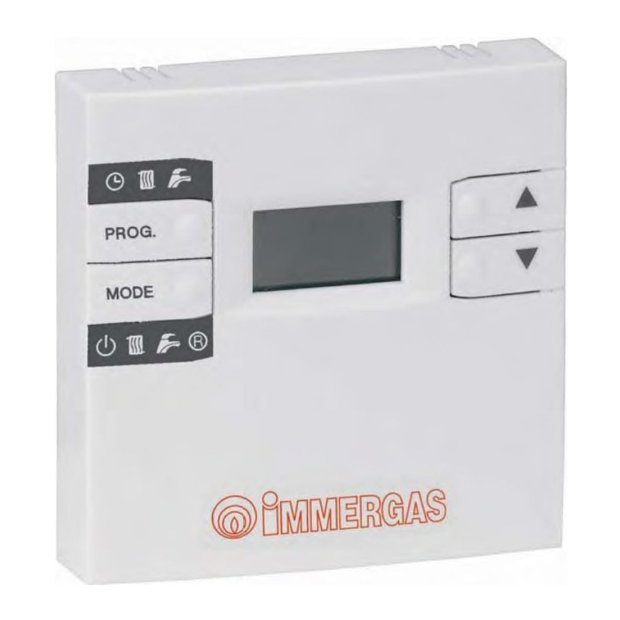
DESCRIPTION OF CONTROLS

 | Access to Programming/Display and operating parameter setting. |
 | Operating mode change / Programming window change / Boiler reset. |
 | Increase of the value selected. |
 | Decrease of the value selected. |
OPERATING MODE
Press button  several times to switch from one operating mode to the other:
OFF  Summer (
  ) Winter + MAN (
 ) Winter + AUTO (
  ) OFF.
In OFF mode, Central heating and DHW are disabled, whereas the Antifreeze function is active.
- Summer (
![]() ) DHW functions are guaranteed, whereas the Central heating functions are disabled (the antifreeze remains active). Buttons
) DHW functions are guaranteed, whereas the Central heating functions are disabled (the antifreeze remains active). Buttons ![]() allow you to view and modify the DHW temperature. In this case, icon
allow you to view and modify the DHW temperature. In this case, icon ![]() switches on and Sn: XX °C is displayed, where XX indicates the configured set point, which flashes).
switches on and Sn: XX °C is displayed, where XX indicates the configured set point, which flashes). - Winter+MAN (manual) icons
![]() and
and ![]() switch on.
switch on.
In this case, the DHW and Central Heating function are both enabled. Buttons![]() allow you to view and modify the room temperature directly and permanently. To return to normal operating mode, press
allow you to view and modify the room temperature directly and permanently. To return to normal operating mode, press ![]() or wait 5".
or wait 5". - Winter+AUTO (automatic) icons
![]() ,
, ![]() and
and ![]() are switched on. In this case, the DHW functions are enabled and the room temperature is adjusted according to the Central Heating time program. Buttons
are switched on. In this case, the DHW functions are enabled and the room temperature is adjusted according to the Central Heating time program. Buttons ![]() allow you to view and modify the room temperature set directly and temporarily (the modification will be valid until the Comfort temperature switches to reduced temperature or vice-versa in the time program set). During this period, icon
allow you to view and modify the room temperature set directly and temporarily (the modification will be valid until the Comfort temperature switches to reduced temperature or vice-versa in the time program set). During this period, icon ![]() flashes. To program two new temperature levels permanently, which will be used by the time program to adjust the room temperature, proceed as indicated in paragraph Programming Comfort and reduced temperature for Central Heating.
flashes. To program two new temperature levels permanently, which will be used by the time program to adjust the room temperature, proceed as indicated in paragraph Programming Comfort and reduced temperature for Central Heating.
 switches on and Sn: XX °C is displayed, where XX indicates the configured set point, which flashes).
 or wait 5".
 are switched on. In this case, the DHW functions are enabled and the room temperature is adjusted according to the Central Heating time program. Buttons
 SETTINGS AND PROGRAMS
Setting the required DHW temperature
Press  to display the DHW set point temperature to display icon , Sn: XX °C and icon. To change the set value (flashing), press
  . To confirm the setting, press button or wait 5".
Setting the Maximum Central Heating Set point temperature allowed
Press button twice to display the Maximum Central Heating set point temperature allowed,  Mr: XX °C and icon
  . To modify the value set (flashing), use buttons . To confirm the setting press button or wait 5".
Setting comfort and reduced room temperature
Press for at least 3" to access the Programming (indicated by icon  ). Press several times to display icons , , and XX.X CA, with XX.X flashing to indicate the Room and Comfort Set point. Use buttons to set the required temperature, which will be used during the Comfort periods programmed for Central Heating. Then press to access icons and and XX.X EA, with XX.X flashing indicate the Reduced Room Set point. Use buttons to set the required temperature, which will be used during the Reduced temperature periods programmed for Central Heating. To return to normal operating mode, press or wait 60".
Programming the day of the week and current time
Press for at least 3" to access the Programming and display 
 and the current time, while the day of the week flashes under
  . To modify the set value (flashing), use buttons (1=Monday, 7=Sunday). Press to set the time. To change the set value (flashing), press . Press to set the minutes. To change the set value (flashing), press . To return to normal operating mode, press or wait 60".
Time programming of the Central heating operation
The time program is a set of 8 times in which the system switches from adjusting the comfort room temperature (ON) to adjusting the reduced room temperature (OFF) and vice-versa.
Note: To exclude a time band, the ON times must correspond to the OFF times.
 Time program set from Monday to Friday.
Saturday and Sunday Comfort from 7.00 to 23.00, Reduced from 23.00 to 7.00.
For Central Heating during comfort periods, the value set as Room Comfort Set point (XX.X CA) is used as Room set point, whereas, during the other periods, the value set as Room Reduced temperature set point (XX.X EA) or Reduced is used.
In the event the pre-set program is not efficient, you can change it as described below:
Press for at least 3" to access the Programming and display icons and and the current time. Press several times to display the fixed icons and  and the flashing icon and the day of the week (flashing).
Use buttons to select the day or group of days in which the modification regarding the heating time programming must be applied:
 1 Monday
2 Tuesday
3 Wednesday
4 Thursday
5 Friday
6 Saturday
7 Sunday
1 5 From Monday to Friday
6 7 Saturday and Sunday
1 6 From Monday to Saturday
1 7 From Monday to Sunday
Press to confirm the day or group of days. The first ON time appears flashing (indicated with icon  and point number 1). Use buttons to select the ON1 time and pass to the subsequent point 2 by pressing . The first OFF time appears flashing (indicated by the absence of icon and point number 2). Use buttons to select the OFF1 time and pass to the subsequent point 3 by pressing . Continue this way until the last point OFF4 is reached (point8). To return to normal operating mode any time, press or wait 60".
Restoring default settings
Press buttons simultaneously for 10" to display CLr (which will disappear). This way, all the default settings and programming will be restored and the user settings will be deleted permanently.
Summary of the default settings
| Function / Window | Factory setting |
| Operating prog. | WINTER |
| Manual Room set point | 20.0°C |
| DHW set | 50°C |
| Regulation Constant | 1.5 |
| Current time | 00:00  1 1 |
| Room Comfort set | 20.0°C |
| Room Economy set | 16.0°C |
| Maximum central heating set | * |
| Building inertia/dimension | 10 |
| Regulation Algorithm Type | 3 |
| Room Antifreeze Temp. | 5.0°C |
| Central Heating time program | Mon..Fri: Comfort 06:00-8:00 / 11:00-13:00 / 17.00-23.00 Sat..Sun: Comfort 07:00-23.00 |
ERRORS AND FAULTS
Faults indications and boiler release
In the presence of a fault, the display will show Er: XX in normal operation mode, where XX indicates the type of fault in the boiler. If Er: XX LC is displayed, the fault can be solved by pressing .
 No communication with the boiler.
SPECIAL FUNCTIONS FOR THE TECHNICIAN
To access the special functions described below, press and then for 3''. Then select the required function by pressing until the corresponding message is displayed. Once you have made the modifications, wait 60" for the mini CRD to return to normal operation.
Regulation algorithm and relative parameters selection
- Regulation Constant: A high parameter value involves a greater Central heating Temperature calculated as the other parameters. Once you have accessed the menu, press
![]() until X.X hr appears, with X.X flashing to indicate the Regulation Constant value. Use buttons
until X.X hr appears, with X.X flashing to indicate the Regulation Constant value. Use buttons ![]() to set the value between 0.5 and 6.5, which will be used during regulation. Wait 60" before returning to normal operating mode
to set the value between 0.5 and 6.5, which will be used during regulation. Wait 60" before returning to normal operating mode - Building dimension or inertia: A high parameter value involves lower reactivity and greater stability of the regulation algorithm. For small environments with low inertia, we recommend low values; for larger environments or in the presence of high inertia, we recommend higher values. To view/modify the value, press
![]() and
and ![]() for 3". Once you have accessed the menu with
for 3". Once you have accessed the menu with ![]() and
and ![]() , press
, press ![]() several times to display icon
several times to display icon ![]() and XX bd, with XX flashing to indicate the Building Dimension value. Use buttons
and XX bd, with XX flashing to indicate the Building Dimension value. Use buttons ![]() to set the value between 1 and 10, which will be used during regulation. Wait 60'' before returning to normal operating mode
to set the value between 1 and 10, which will be used during regulation. Wait 60'' before returning to normal operating mode - Algorithm type (room or modulation probe exclusion): The type of algorithm to be used during regulation can be selected according to the value assigned to an associated variable. Once you have accessed the menu with
![]() and
and ![]() , press
, press ![]() several times to display icon
several times to display icon ![]() and X AL, with X flashing to indicate the value of the regulation algorithm type selected. Use buttons
and X AL, with X flashing to indicate the value of the regulation algorithm type selected. Use buttons ![]() to set the required value (0 / 3).
to set the required value (0 / 3).
The meaning of the values is the following:
| 0 AL | room and modulating probes deactivated (the system runs with Central Heating Set Point fixed and settable by the user: (Maximum Central Heating Set point), regardless of the room temperature level). |
| 1 AL | room probe deactivated and modulation probe activated (the system runs with variable Central Heating Set Point calculated according to the Regulation Constant, regardless of the room temperature level). |
| 2 AL | room probe activated and modulating probe deactivated (the system runs with fixed Central Heating set point settable when the room temperature is below that set and remains off when it is exceeded) |
| 3 AL | room probe and modulation probe activated (the system runs with variable Central Heating Set Point calculated according to the Regulation Constant and at the room temperature compared to that set). |
To return to normal operating mode, press or wait 60".
TECHNICAL FEATURES
- Connection to boiler via non-polarised twisted pair
(2x0.75 mm, maximum length 50 m). - No auxiliary supply voltage or batteries are required.
- Load reserve time in the absence of connection/supply voltage for at least 8 hours.
- User's settings and programming permanent memorisation.
- Operating temperature range 0 – 50°C
- Measurement precision ±0.5°C at 25°C.
- Max clock diversion ±15 minutes / year.
- Electric construction standard EN 60730-1.
Product specifications
In accordance with Regulation 811/2013 the temperature control device class is:
| Class | Contribution to the environmental heating seasonal energy efficiency | Description |
| V | +3% | Mini CRD |
| VI | +4% | Mini CRD coupled to outer sensor |

Documents / ResourcesDownload manual
Here you can download full pdf version of manual, it may contain additional safety instructions, warranty information, FCC rules, etc.
Download Immergas Mini CRD - Mini Digital Remote Control Instruction Sheet
Advertisement
Thank you! Your question has been received!


Need Assistance?
Do you have a question about the Mini CRD that isn't answered in the manual? Leave your question here.