Table of Contents
Advertisement
Quick Links
Advertisement
Table of Contents

Related Manuals for Teledyne Lecroy WaveSurfer 3024Z


Summary of Contents for Teledyne Lecroy WaveSurfer 3024Z
- Page 1 Operator's Manual WaveSurfer 3000z Oscilloscopes...
- Page 2 Resale or unauthorized duplication of Teledyne LeCroy publications is strictly prohibited. Teledyne LeCroy is a trademark of Teledyne LeCroy, Inc., Inc. Other product or brand names are trademarks or requested trademarks of their respective holders. Information in this publication supersedes all earlier versions.
-
Page 3: Table Of Contents
Contents Oscilloscope Overview and Setup Safety Overview Positioning the Feet Connecting to Other Devices/Systems Powering On/Off Software Activation Language Selection Using MAUI Touch Screen Touch Screen Actions Controlling Traces Zooming Print/Screen Capture Acquisition Auto Setup Vertical Digital (Mixed Signal) Timebase Trigger Viewing Acquisition Status Display... - Page 4 Index Welcome Thank you for purchasing a Teledyne LeCroy WaveSurfer oscilloscope. We're certain you'll be pleased with the detailed features unique to our instruments. Take a moment to verify that all items on the packing list or invoice copy have been shipped to you.
-
Page 5: Oscilloscope Overview And Setup
Oscilloscope Overview and Setup Oscilloscope Overview and Setup Safety Symbols These symbols appear on the instrument or in documentation to alert you to important safety concerns: Caution of potential damage to instrument or Warning of potential bodily injury. Refer to manual. - Page 6 WaveSurfer 3000z Oscilloscopes Operator's Manual Operating Environment Temperature : 0 °C to 50 °C Humidity : Maximum relative humidity 90% up to 31 °C, decreasing linearly to 50% relative humidity at 40 °C Altitude : Up to 10,000 ft (3,048 m) at or below 30 °C Measuring Terminal Ratings (C1-C4 and Ext) Caution: Measuring terminals have no rated measurement category per IEC/EN 61010-1:2010.
- Page 7 Oscilloscope Overview and Setup Power The instrument operates from a single-phase, 100 to 240 Vrms (± 10%) AC power source at 50/60 Hz (± 5%), or a 100 to 120 Vrms (± 10%) AC power source at 400 Hz (± 5%). The instrument automatically adapts to the line voltage.
-
Page 8: Overview
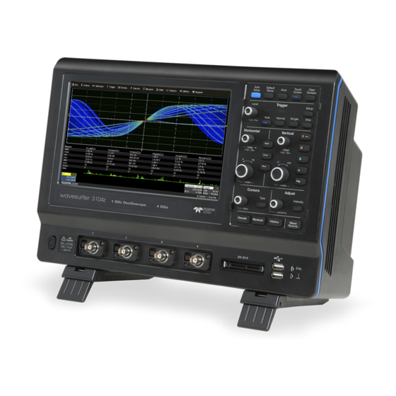
WaveSurfer 3000z Oscilloscopes Operator's Manual Overview Front Input/Output A. Power button. B. Channel inputs 1-4 for analog signals. C. Mixed signal interface for digital inputs (WS3K-MSO required). D. Front-mounted host USB port for transferring data or connecting peripherals such as a mouse or keyboard. - Page 9 Oscilloscope Overview and Setup Front Panel The Front Panel houses "hard" controls for basic oscilloscope functions. See the later sections of this manual for instructions on using the touch screen to make the settings described here. All the knobs on the front panel function one way if turned and another if pushed like a button.
- Page 10 WaveSurfer 3000z Oscilloscopes Operator's Manual Horizontal Controls The Delay knob changes the Trigger Delay value (S) when turned. Push the knob to reset Delay to zero. The Horizontal Adjust knob sets the Time/division (S) of the oscilloscope acquisition system when the trace source is an input channel.
- Page 11 Oscilloscope Overview and Setup Signal Interfaces Teledyne LeCroy instruments offer a variety of interfaces to input analog or digital signals. See the oscilloscope product page at teledynelecroy.com for a list of compatible input devices. ProBus Interface Channel inputs C1-C4 utilize the ProBus interface.
- Page 12 Active Probes Teledyne LeCroy offers a variety of active probes for use with your oscilloscope. Most active probes match probe to oscilloscope response automatically using probe response data stored in an on-board EEPROM. This ensures the best possible combined probe plus oscilloscope channel frequency response without the need to perform any de-embedding procedure.
-
Page 13: Positioning The Feet
Oscilloscope Overview and Setup Positioning the Feet The WaveSurfer is equipped with rotating, tilting feet to allow four different viewing positions. To tilt the body back slightly for bench top viewing, pull the small flaps on the bottom of the feet away from the body of the oscilloscope. To tilt the body forward, rotate both feet to the back. -
Page 14: Powering On/Off
WaveSurfer 3000z Oscilloscopes Operator's Manual Printer WaveSurfer 3000 supports PictBridge-compliant printers. Connect the printer to any host USB port. Go to Utilities > Utillities Setup > Hardcopy to configure printer settings. Trigger Out To send a trigger out pulse to another device, connect a BNC cable from Aux Out on the back of he instrument to the other device. -
Page 15: Software Activation
Oscilloscope Overview and Setup Software Activation The oscilloscope software (firmware and standard applications) is active upon delivery. At power-up, the instrument loads the software automatically. Free firmware updates are available periodically. Visit the software download page of our website at teledynelecroy.com and go to Oscilloscope Downloads >... - Page 16 WaveSurfer 3000z Oscilloscopes Operator's Manual...
-
Page 17: Using Maui
Using MAUI Using MAUI MAUI (Most Advanced User Interface) is Teledyne LeCroy's unique oscilloscope user interface. Touch Screen The oscilloscope features a capacitive touch screen that supports fluid, tablet-like response to gestures. Note: Use your finger or a capacitive stylus (not included) to interact with the touch screen. A regular stylus will not work. - Page 18 WaveSurfer 3000z Oscilloscopes Operator's Manual Grids The grids display the waveform traces. Every grid is 8 vertical divisions representing the full number of vertical levels and 10 horizontal divisions. The value represented by each division depends on the Vertical and Horizontal Scale of the traces that appear on the grid. The grid region can be divided up to three times to show channel (Cn), math (Fn), and zoom (Zn) traces on different grids.
- Page 19 Using MAUI Descriptor Boxes Trace descriptor boxes appear just beneath the grid whenever a trace is turned on. They function to: Inform—descriptors summarize the current trace settings and its activity status. Navigate—touch the descriptor box once to activate the trace, twice to open the setup dialog. Configure—drag-and-drop descriptor boxes to change source or copy setups (with OneTouch).
- Page 20 WaveSurfer 3000z Oscilloscopes Operator's Manual Dialogs Dialogs appear at the bottom of the display for entering setup data. The top dialog will be the main entry point for the selected functionality. For convenience, related dialogs appear as a series of tabs behind the main dialog.
- Page 21 Message Bar At the bottom of the oscilloscope display is a narrow message bar. The current date and time are shown at the far right. Status, error, or other messages are shown at the far left, where "Teledyne LeCroy" normally appears.
-
Page 22: Touch Screen Actions
WaveSurfer 3000z Oscilloscopes Operator's Manual Touch Screen Actions Touch, drag, and swipe can be used to create and change setups with one touch. Just as you change the display by using the setup dialogs, you can change the setups by moving different display objects. Use the setup dialogs to refine touch screen actions to precise values. -
Page 23: Controlling Traces
Using MAUI Controlling Traces Traces are the visible representations of waveforms that appear on the display grid. They may show live inputs (Cn, Digitaln), a math function applied to a waveform (Fn), a stored memory of a waveform (Mn), a zoom of a waveform (Zn), or the processing results of special analysis software. - Page 24 WaveSurfer 3000z Oscilloscopes Operator's Manual Adjusting Traces To adjust Vertical Scale and Offset, or Horizontal Scale and Delay, just activate the trace and use the front panel knobs. To make other adjustments—such as units—touch the trace descriptor box twice to open the appropriate setup dialog. Many settings are adjusted by selecting from the pop-up that appears when you touch a control.
- Page 25 Using MAUI Labeling Traces The Label function gives you the ability to add custom annotations to the trace display. Once placed, labels can be moved to new positions or hidden while remaining associated with the trace. Create Label 1. Select Label from the context menu, or touch the Label Action toolbar button on the trace setup dialog.
-
Page 26: Zooming
WaveSurfer 3000z Oscilloscopes Operator's Manual Zooming Zooms magnify a selected region of a trace by altering the horizontal and/or vertical scale relative to the source trace. Zooms may be created in several ways, using either the front panel or the touch screen. You can adjust zooms the same as any other trace by using the front panel Vertical and Horizontal knobs or the touch screen zoom factor... - Page 27 Using MAUI Zn Dialog Each Zn dialog reflects the center and scale for that zoom. Use it to adjust each zoom independently. Trace Controls Trace On shows/hides the zoom trace. It is selected by default when the zoom is created. Source lets you change the source of the zoom to any digital, math or memory trace while maintaining all other settings.
- Page 28 WaveSurfer 3000z Oscilloscopes Operator's Manual Creating Zooms Any type of trace can be zoomed by creating a new zoom trace (Zn) following the procedures here. All zoom traces open in the same grid, with the zoomed portion of the source trace left unshaded. Zoomed area of source trace left unshaded.
-
Page 29: Print/Screen Capture
Using MAUI Close Zoom New zooms are turned on and visible by default. If the display becomes too crowded, you can close a particular zoom and the zoom settings are saved in its Zn slot, ready to be turned on again when desired. To close the zoom, clear the Trace On box on the Zoom or Zn dialog. - Page 30 WaveSurfer 3000z Oscilloscopes Operator's Manual...
-
Page 31: Acquisition
Acquisition Acquisition The acquisition settings include everything required to produce a visible trace on screen and an acquisition record that may be saved for later processing and analysis: Vertical axis scale at which to show the input signal, and probe characteristics that affect the signal Horizontal axis scale at which to represent time, sampling mode and sampling rate Acquisition... -
Page 32: Vertical
Full vertical setup is done on the Cn dialog. To access it, choose Vertical > Channeln Setup from the menu bar, or touch the Channel descriptor box. If a Teledyne LeCroy probe is connected, its Probe dialog appears to the right of the Cn dialog. Vertical Settings The Trace On checkbox turns on/off the channel trace. - Page 33 When a Teledyne LeCroy probe is connected to a channel input, the Attenuation field becomes a button to access the Probe dialog, a tab added to the right of the Cn tab. Enter Attenuation on the Probe dialog.
- Page 34 WaveSurfer 3000z Oscilloscopes Operator's Manual Auto automatically raises attenuation when V/div is >7.9 or lowers attenuation when V/div is <7.9, allowing you to properly view the input waveform. Lock to High locks attenuation to the highest setting, regardless of the V/div setting. Maintaining a high attenuation will allow small signals on larger voltage waveforms to be accurately measured.
-
Page 35: Digital (Mixed Signal)
Acquisition Digital (Mixed Signal) When a Mixed Signal device is connected to the oscilloscope, digital input options are added to the Vertical menu. There are set up dialogs for each possible digital group, Digital1 to Digitaln, which correspond to digital buses. You choose which lines make up each digital group, what they are named, and how they appear on the display. - Page 36 WaveSurfer 3000z Oscilloscopes Operator's Manual Digital Setup Using Digital Leadset The digital leadset enables input of up-to-16 lines of digital data. Physical lines can be preconfigured into different logical groups, Digitaln, corresponding to a bus. The transitions for each line may be viewed through different displays.
- Page 37 Acquisition 4. When you're finished on the Digitaln dialog, open Logic Setup and choose the Logic Family that applies to each digital bank, or set custom Threshhold values. Digital Display Setup Choose the type and position of the digital traces that appear on screen for each digital group. 1.
- Page 38 WaveSurfer 3000z Oscilloscopes Operator's Manual Renumbering Digital Lines Labels can also be "swapped" between lines. This procedure helps in cases where the physical lead number is different from the logical line number you would like to assign to that input. It can save time having to reattach leads or reconfigure groups.
-
Page 39: Timebase
Acquisition Timebase Timebase (Horizontal) settings control traces along the X axis. The timebase is shared by all channels. The time represented by each horizontal division of the grid, or Time/Division, is most easily adjusted using the front panel Horizontal knob. Full Timebase set up is done on the Timebase dialog, accessed either by choosing Timebase >... - Page 40 WaveSurfer 3000z Oscilloscopes Operator's Manual Memory Maximum Points is the maximum number of samples taken per acquisition. The actual number of samples acquired can be lower due to the other timebase settings. The oscilloscope will allot the maximum memory and sample rate possible based on the activity within each pair of channels.
- Page 41 Acquisition Note: RIS is not available when the oscilloscope is using another form of digital interleaving. Roll Sampling Mode Roll mode displays incoming points of slow timebase acquisitions so that the trace appears to "roll" continuously across the screen from right to left. The acquisition is complete when a trigger event is detected, at which point the next acquisition begins immediately.
- Page 42 WaveSurfer 3000z Oscilloscopes Operator's Manual Sequence Mode Set Up The Sequence dialog appears only when Sequence Mode sampling is selected. Use it to define the number of fixed-size segments to be acquired. 1. From the menu bar, choose Timebase > Horizontal Setup..., then Sequence Sampling Mode. 2.
- Page 43 Acquisition Set Reference Clock By default, the oscilloscope is set to use its internal clock of 10 MHz as the Timebase reference to synchronize acquisition across all channels. You can opt to use an external reference clock for this purpose. Connect the clock source to the REF IN input on the back I/O panel of the oscilloscope using a BNC cable.
- Page 44 WaveSurfer 3000z Oscilloscopes Operator's Manual display, then use the buttons to navigate the history of acquisitions. Top row buttons scroll: Fast Backward, Slow Backward, Slow Forward, Fast Forward. Bottom row buttons step: Back to Start, Back One, Go to Index (row #), Forward One, Forward to End. Press Pause when you see something of interest, then use the History table to find the exact Index.
-
Page 45: Trigger
Acquisition Trigger Triggers define the event around which digitized information is displayed on the grid. Different Trigger Types are used to select different events in the trigger source waveforms: edge voltages, pulse widths, high/low states, etc. These may be a single channel event or a complex pattern of events across several channels. - Page 46 WaveSurfer 3000z Oscilloscopes Operator's Manual Trigger Types The Trigger Type sets the triggering conditions. Edge triggers upon a achieving a certain voltage level in the positive or negative slope of the waveform. Width triggers upon finding a positive- or negative-going pulse width when measured at the specified voltage level.
- Page 47 Acquisition Trigger Set Up To open the Trigger dialog, press the front panel Trigger Setup button or touch the Trigger descriptor box. Different controls will appear depending on the Trigger Type selected (e.g., Slope for Edge triggers). Complete the settings shown after making your selection. The trigger condition is summarized in a preview window at the far right of the Trigger dialog.
- Page 48 WaveSurfer 3000z Oscilloscopes Operator's Manual Conditions (Smart Triggers) Smart triggers all allow you to apply Boolean logic to refine the triggering condition beyond simply Level and Slope/Polarity. The values that satisfy the operators of Less Than, Less Than or Equal To, Greater Than, etc. can be set by entering an Upper Value and/or Lower Value.
- Page 49 Acquisition 4. To set a Time Condition in which the pattern must occur once the trigger is armed, choose the operator: Less Than to trigger only if the pattern occurs before the time set. Greater Than to trigger only if the pattern occurs after the time set. In Range to set a time window in which the pattern must occur.
- Page 50 WaveSurfer 3000z Oscilloscopes Operator's Manual Qualified Trigger A Qualified trigger arms on the A event, then triggers on the B event. In Normal trigger mode, it automatically resets after the B event, and re-arms upon the next matching A event. Unlike a basic Edge or Pattern trigger with Holdoff, the A and B events can occur in different signals, allowing you to use the state of one signal to "qualify"...
- Page 51 Acquisition Trigger Holdoff Holdoff is either a period of time or an event count that may be set as an additional condition for Edge and Pattern triggers. Holdoff disables the trigger temporarily, even if the other conditions are met. Use Holdoff to obtain a stable trigger for repetitive, composite waveforms.
- Page 52 WaveSurfer 3000z Oscilloscopes Operator's Manual Note: Because there is only one trigger per acquisition, the trigger event will always belongs to the new acquisition. The processing time shown here is for purposes of illustration only. Regardless of where in the acquisition record the trigger event was found (first edge or last), the display will show time pre- and post-trigger based on your Time/Div and Delay settings.
-
Page 53: Viewing Acquisition Status
Acquisition Choose to Holdoff by Time (the clock) or Events. If using Holdoff by Time, enter the Time in S to wait before triggering. If using Holdoff by Events, enter the number of Events to wait before triggering. Choose to Start Holdoff Counter On: Current Acquisition Start time. - Page 54 WaveSurfer 3000z Oscilloscopes Operator's Manual...
-
Page 55: Display
Display Display Display settings affect the number and style of grids that appear on screen and some of the visual characteristics of traces, such as persistence. Auto Grid is enabled by default. This feature divides the screen as needed when new traces open. WaveSurfer oscilloscopes may be divided into a maximum of three grids—one each for channels/memories, math functions, and zooms—that each represent the full number of vertical levels. - Page 56 WaveSurfer 3000z Oscilloscopes Operator's Manual On WaveSurfer oscilloscopes, Axis labels display the values associated with the top and bottom grid lines (calculated from Volts/div) and the time associated with the extreme left and right grid lines (calculated from the Time/div). Trace Choose a line style for traces: solid Line or disconnected sample Points.
-
Page 57: Persistence Display
Display Persistence Display The Persistence feature retains waveform traces on the display for a set amount of time before allowing them to gradually "decay," similar to the analog-style display of old, phosphor screen oscilloscopes. The display is generated by repeated sampling of events over time and the accumulation of the sampled data into "persistence maps". - Page 58 WaveSurfer 3000z Oscilloscopes Operator's Manual from the display. 5. You can superimpose the last waveform over the persistence map by selecting Show Last Trace. Remove Persistence To turn off persistence and return to the regular trace style, clear the Persistence On checkbox.
-
Page 59: Math And Measure
Math and Measure Math and Measure Teledyne LeCroy offers a rich set of standard, pre-programmed tools for the "quickest time to insight" into the characteristics of acquired waveforms. Most instruments calculate measurements for all samples in an acquisition, enabling you to rapidly and thoroughly calculate thousands or millions of parameter values and apply a variety of mathematical functions to the input waveform trace. - Page 60 WaveSurfer 3000z Oscilloscopes Operator's Manual When the X1 arrow is higher than the X2 arrow, this will be a negative number, as it represents a drop (e.g., in voltage), even when X2 is positioned above the zero level. When the X1 arrow is lower than the X2 arrow, this will be a positive number, as it represents a rise.
- Page 61 Math and Measure Alternatively, use the Front Panel Cursor knob. Push the knob until the correct cursor is selected, then turn the knob to move it. The third press of the Cursor knob selects both cursors so they will track together when the knob is turned. When there are multiple traces on the same grid, first bring the desired trace to the foreground by touching the trace or its descriptor box.
-
Page 62: Measure
WaveSurfer 3000z Oscilloscopes Operator's Manual Measure Parameters are tools that give you access to a wide range of waveform properties, such as Rise Time, RMS voltage and Peak-Peak voltage. Parameter readouts are shown in a dynamic Measure table that appears below the waveform grids. All active measurements can be used as inputs to other processes, such as math functions, even when the Measure table is hidden from view. - Page 63 Math and Measure Parameter Set Up The Measure Dialog gives quick access to measurement features. Besides configuring parameters, use the Measure dialog to show statistics and histicons, or to gate measurements. 1. To open the Measure dialog, touch the Add New box and select Measurement, or choose Measure >...
- Page 64 WaveSurfer 3000z Oscilloscopes Operator's Manual The maximum value of the parameter measured over the number of times shown. Sdev The population standard deviation of the parameter calculated over the number of times shown. For any parameter that computes once on an entire acquisition, Num represents the num- ber of sweeps over which the statistics are computed.
- Page 65 Math and Measure Using Trends The Trend math function plots a waveform composed of parameter measurements arranged in the order the measurements were made. The vertical units are the source parameter values, and the horizontal unit is the measurement number. The Trend contains a single value for each unique measurement, and therefore may not be time synchronous with the source waveform, where the same measured value may occur successively over time.
- Page 66 WaveSurfer 3000z Oscilloscopes Operator's Manual List of Standard Measurements Note: Unless otherwise stated, measurements are calculated according to IEEE standards. Additional measurements may be available depending on the software options installed. Amplitude Difference between the upper and lower levels in two-level (bi-modal) signals, calculated using the formula for Top-Base.
- Page 67 Math and Measure Frequency Reciprocal of each Period of a cyclic signal. Period is measured as time between every pair of 50% crossings on the rising edge, starting with the first rising transition after the left measurement gate. Maximum Largest vertical value in a waveform. Unlike Top, does not assume the waveform has two levels. Mean Average of vertical values in a waveform.
- Page 68 WaveSurfer 3000z Oscilloscopes Operator's Manual Rise Time Duration of a pulse waveform's rising transition from 10% to 90% of amplitude, averaged for all rising transitions between the measurement gates. On signals that do not have two major levels (such as triangle waves), the Top-Base measurement used to calculate rise can default to maximum and minimum, giving less predictable results.
-
Page 69: Math
Math and Measure Math Math function traces (Fn) display the result of applying a mathematical operation to a source trace. The output of a math function is always another trace, whereas the output of a measurement parameter is a tabular readout of the measurement. Math can be applied to any channel (Cn), zoom (Zn), or memory (Mn) trace. - Page 70 WaveSurfer 3000z Oscilloscopes Operator's Manual A Summary of the function you are building appears on the dialog. Refer to this to be sure your sources are in the proper order to yield the function you want (e.g., C1-C2 vs. C2-C1). 4.
- Page 71 Math and Measure Average Function The summed or continuous average of all data samples from multiple acquisitions can be displayed as a new waveform trace using the Average function. Setting Up Averaging To apply Continuous or Summed Averaging as a Math function: 1.
- Page 72 WaveSurfer 3000z Oscilloscopes Operator's Manual Sweep New Average = (new data + 2 * old average)/(2 + 1) = 1/3 new data + 2/3 old average (new data + 3 * old average)/(3 + 1) = 1/4 new data + 3/4 old average (new data + 4 * old average)/(4 + 1) = 1/5 new data + 4/5 old average (new data + 4 * old average)/(4 + 1) = 1/5 new data + 4/5 old average (new data + 4 * old average)/(4 + 1) = 1/5 new data + 4/5 old average...
- Page 73 Math and Measure Resolution Increase -3 dB Bandwidth (x Nyquist) Filter Length (Samples) 0.121 0.058 0.029 0.016 With low-pass filters, the actual SNR increase obtained in any particular situation depends on the power spectral density of the noise on the signal. The improvement in SNR corresponds to the improvement in resolution if the noise in the signal is white (evenly distributed across the frequency spectrum).
- Page 74 WaveSurfer 3000z Oscilloscopes Operator's Manual FFT Function For a large class of signals, you can gain greater insight by looking at spectral representation rather than time description. Signals encountered in the frequency response of amplifiers, oscillator phase noise and those in mechanical vibration analysis, for example, are easier to observe in the frequency domain. If sampling is done at a rate fast enough to faithfully approximate the original waveform (usually five times the highest frequency component in the signal), the resulting discrete data series will uniquely describe the analog signal.
- Page 75 Math and Measure Window Type Applications and Limitations Rectangular Normally used when the signal is transient (completely contained in the time-domain window) or known to have a fundamental frequency component that is an integer multiple of the fundamental frequency of the window. Signals other than these types will show varying amounts of spectral leak- age and scallop loss, which can be corrected by selecting another type of window.
- Page 76 WaveSurfer 3000z Oscilloscopes Operator's Manual Rescale Function The Rescale function allows you to create a new function trace that rescales another trace by applying a multiplication factor (a) and additive constant (b). You can also use it as a way to view the function source in a different unit of measure.
- Page 77 Math and Measure Category Unit Mnemonic Mass gram slug SLUG Volume liter cubic meter cubic inch cubic foot cubic yard YARD3 Angle radian arcdegree arcminute arcsecond cycle CYCLE revolution turn TURN Force/Weight Newton grain ounce pound Velocity meters/second inches/second IN/S feet/second FT/S yards/second...
- Page 78 WaveSurfer 3000z Oscilloscopes Operator's Manual Category Unit Mnemonic Energy Joule British Thermal Unit calorie Rotating Machine radians/second RADPS frequency (Hertz) revolutions/second revolutions/minute torque N•m torque in•oz INOZ torque in•lb INLB torque ft•lb FTLB power, mechanical (Watt) horsepower Magnetic Weber Tesla inductance (Henry) magnetic field strength permeability...
- Page 79 Math and Measure Category Unit Mnemonic Time second minute hour HOUR week WEEK Dimensionless percent percent min-max PCTMNMX decibel decibel milliwatt decibel Volt decibel millivolt DBMV decibel microvolt DBUV decibel microampere DBUA decibel referred to carrier decade DECADE unit interval Q-scale byte BYTE...
- Page 80 WaveSurfer 3000z Oscilloscopes Operator's Manual List of Standard Math Operators Note: The installation of software options on the oscilloscope may add math operators to this list. Absolute Calculates distance away from zero for every point in the waveform. For values greater than zero, this is the same as the value.
- Page 81 Math and Measure Each calculated area is summed with the previous sum of areas. The multiplier and adder are applied before the integration function. Invert For every point in the waveform, the inverse of that point is calculated. Product For every point in the waveform, the value of Source1 is multiplied by the value of Source 2. Source1 and Source2 must have the same horizontal units and scale.
-
Page 82: Memory
Import External Waveform Files into Memory Trace (.trc) files saved on other Teledyne LeCroy instruments can also be imported into internal memory using the waveform recall feature. Choose File > Recall Waveform and to recall the file to an internal memory. - Page 83 Math and Measure Note: On WaveSurfer 3000/3000z oscilloscopes, the removable MicroSD card serves as internal memory for saving .trc files. Restoring Memories The Memories dialog is a convenient panel for restoring saved memories to the display. Access the Memories dialog by pressing the front panel Mem button or choosing Math > Memory Setup. Check On next to the memory trace you wish to display.
- Page 84 WaveSurfer 3000z Oscilloscopes Operator's Manual...
-
Page 85: Analysis Tools
Analysis Tools Analysis Tools The Analysis menu tools complement the standard math and measurements to help you understand the behavior of waveforms. WaveScan searches single or multiple acquisitions for events that meet specific criteria. Pass/Fail Testing shows whether waveforms meet mask test limits. Optional software packages may be purchased for specialized uses, such as power analysis. - Page 86 WaveSurfer 3000z Oscilloscopes Operator's Manual Setting Up WaveScan Set up your source channel and triggers before setting up the scan. 1. Press the front panel Stop button to stop acquisition. 2. Choose Analysis > WaveScan and check Enable. 3. Choose the Source waveform. 4.
- Page 87 Analysis Tools Non-monotonic Mode Non-monotonic Mode looks for edges that cross a threshold more than once between high and low levels. All events that meet the criteria of slope, hysteresis, and level are presented in a table and highlighted in the source trace.
- Page 88 WaveSurfer 3000z Oscilloscopes Operator's Manual Bus Pattern Mode Bus Pattern Mode (only on Mixed Signal models) is used for finding 2- to 16-bit patterns across the digital lines. Bus Pattern Mode settings are: Viewing. Choose to enter the pattern as Binary or Hex(adecimal). Binary/Hex.
-
Page 89: Pass/Fail Testing
Analysis Tools PASS/FAIL Testing PASS/FAIL testing is a type of mask testing that is particularly useful for comparing newly acquired signals to a previously acquired "golden standard" waveform. The software counter will update in real time as new acquisitions are compared to the mask, and colored markers will quickly show those areas of the waveform that violate the mask. - Page 90 WaveSurfer 3000z Oscilloscopes Operator's Manual Load Mask Use this procedure in lieu of Make Mask if you have a pre-defined mask file. 1. Open the Load Mask subdialog. 2. Touch File and select the mask. 3. Check View Mask to display the mask over the trace. Remove a Mask from the Display Touch the Delete Mask button at the left of the Pass/Fail dialog.
-
Page 91: Save / Recall
Save / Recall Save / Recall The Save/Recall dialog displays a series of shortcut buttons launching the various Save/Recall functions. You can use these buttons or the tabs to navigate to the other Save/Recall dialogs. Save Setups Save Setups allows you to quickly save up-to-six panel settings to internal storage, while Recall Setups restores them with a touch. -
Page 92: Recall Setups
WaveSurfer 3000z Oscilloscopes Operator's Manual Recall Setups Recall Setups restores setups saved to one of the internal memory locations, or enables you to import a setup file. Choose File > Recall Setup... from the menu bar. Recall Setup from Memory Touch one of the six Recall buttons under Recall From Internal Setup.. -
Page 93: Save Waveforms
(e.g., XYZ32a). 4. Touch Data Format and select a file format: Binary, Teledyne LeCroy's binary file format (.trc). Binary results in the smallest possible file size, and is necessary for recalling waveforms to Teledyne LeCroy instruments. - Page 94 WaveSurfer 3000z Oscilloscopes Operator's Manual Note: Binary files can be converted to ASCII using Teledye LeCroy utilities such as ScopeExplorer or WaveStudio. ASCII text file (.txt extension). MATLAB text file (.dat extension). Excel text file (.csv extension). MathCad text file (.prn extension). Audio .wav file.
-
Page 95: Recall Waveforms
Save / Recall Recall Waveforms Use Recall Waveform to restore previously saved waveform files to the display. Note: Only files saved in binary format (.TRC) can be recalled to the touch screen. Choose File > Recall Waveform from the menu bar. Recall Waveform From Memory 1. -
Page 96: Save Table Data
WaveSurfer 3000z Oscilloscopes Operator's Manual Save Table Data The Save Table function saves tabular measurement data displayed on screen to an Excel or ASCII file. By default, files are saved on the MicroSD card, although you can choose a USB drive. Access the Save Table dialog by choosing File >... -
Page 97: Auto Save
Save / Recall Auto Save Data that appears on the oscilloscope display—such as waveforms, measurement readouts and decoder data—can be very dynamic and difficult to read from the oscilloscope unless you stop the acquisition. The Auto Save enables you to automatically store waveform and table data to a file that can be recalled to the oscilloscope later or saved permanently to external storage. -
Page 98: Labnotebook
WaveSurfer 3000z Oscilloscopes Operator's Manual LabNotebook The LabNotebook feature allows you to create and save Notebook Entries containing all setups, a capture of all displayed waveforms and waveform data, to which you may add custom annotations. Notebook Entries are stored in an internal database and are available to be recalled to the touch screen at any time. - Page 99 Save / Recall Manage Notebook Entries First select the entry from the My Notebook Entries list. Edit Notebook Entries 1. Select the entry from the My Notebook Entries list. 2. Go to the second tab labeled with the entry name. 3.
- Page 100 WaveSurfer 3000z Oscilloscopes Operator's Manual LabNotebook Preferences To modify the behavior of the LabNotebook tool, change settings on the LabNotebook Preferences dialog: Prompt for Entry Title Before Saving will cause a pop-up for entering a custom Title and Description to appear when a new entry is created.
-
Page 101: Utilities
The Service button to the far right of the dialog launches a section of the application reserved for qualified Teledyne LeCroy service personnel. An access code is required to enter this section. Status The Utilities Status dialog displays information about your instrument including model number, serial number, firmware version, and installed hardware and software options. - Page 102 The Remote dialog contains settings to configure remote control of the instrument and also network access. Supported remote control protocols are: TCPIP (Ethernet). If you choose this option for remote control, also install Teledyne LeCroy's VICP drivers on the controller. These are included in the VICP Passport plug-in, available free from the software download page at teledynelecroy.com...
- Page 103 Utilities Enter Network ID The network file sharing capabilities require that the oscilloscope have access to the network domain and shares. Use the Network ID settings to enter network credentials. Once credentials have been saved, the oscilloscope should connect to the network seamlessly; you do not need to re-enter credentials unless you wish to change them.
- Page 104 WaveSurfer 3000z Oscilloscopes Operator's Manual Note: : WaveSurfer 3000 oscilloscopes support PictBridge-compatible printers. Printers can be connected via LAN (Ethernet) or USB. 1. From the menu bar, choose File > Print Setup... or Utilities > Utilities Setup > HardCopy. 2. On the Utilities Hardcopy dialog, choose Printer. 3.
- Page 105 Utilities 6. To go on and set up the e-mail connection, touch Configure E-Mail Server and recipient. This will take you to the Preferences E-Mail dialog. Choose Print Color Scheme To change the color of your print output, touch the Color button on the Hardcopy dialog and choose from: Standard(default) - prints objects on a black background, as they appear on the display.
- Page 106 WaveSurfer 3000z Oscilloscopes Operator's Manual Date/Time Date/Time settings control the instrument's timestamp. These numbers appear in the message bar and on tables/records internal to the oscilloscope application, such as History Mode and WaveScan. Note: On Windows 10 oscilloscopes, first switch to the Admin User LCRYADMIN to change the Date/Time settings.
- Page 107 Utilities Options Many optional software packages are available to extend the Analysis functions of the instrument. When you purchase an option, you will receive a key code by email that activates the new functionality. Use the Options dialog to activate software options by installing the key code. This dialog also displays the ScopeID and Serial #.
-
Page 108: Disk Utilities
WaveSurfer 3000z Oscilloscopes Operator's Manual Disk Utilities Use the Disk Utilities dialog to manage files and folders on your instrument's hard drive. Disk Space information is shown at the far right of the dialog for convenience. Access the Disk Utilities dialog by selecting Utilities > Disk Utilities from the menu bar. Delete a Single File 1. - Page 109 Utilities Back Up Files Touch Backup to back up the entire contents of the hard drive to a removable storage device. If a USB drive is installed, you can choose to back up to USB or to the removable Storage Card (MicroSD Card). Otherwise, Storage Card is the default.
-
Page 110: Preferences Dialogs
WaveSurfer 3000z Oscilloscopes Operator's Manual Preferences Dialogs Preference settings have mostly to do with the appearance and performance of the instrument itself, rather than its interaction with other devices/systems. These settings are called "non-volatile," because they are not lost when the oscilloscope is restarted and do not change when a setup panel is recalled. Access the Preferences dialogs by choosing Utilities >... - Page 111 Utilities Calibrate All—all possible combinations of vertical and horizontal settings are calibrated at the current temperature. This calibration is valid for the current temperature ± 5° C and takes about 120 minutes. Caution: It is required that all inputs be removed from the oscilloscope prior to performing calibration.
- Page 112 Miscellaneous These other Preference settings are located on the Miscellaneous dialog. To add the Teledyne LeCroy logo to print output, check Print Teledyne LeCroy Logo When Printing Grid Area Only. This identifies the instrument as the source of the image.
-
Page 113: Wavesource Automatic Waveform Generator
Utilities WaveSource Automatic Waveform Generator The WaveSource Automatic Waveform Generator allows you to output custom sine, square, triangle, pulse, DC, noise, and arbitrary waveforms from the oscilloscope. Connect a BNC cable from the WaveSource output on the back of the oscilloscope to the external device. Output is continuous once WaveSource is enabled. - Page 114 WaveSurfer 3000z Oscilloscopes Operator's Manual 1. Choose Utilities > WaveSource or touch the front panel WaveSource button. 2. Select the Load level. 3. Choose Waveform type ARB. 4. Touch Browse next to the File Name field and browse to the location of the arbitrary waveform file on either the Storage Card or the USB Disk.
-
Page 115: Digital Voltmeter
Utilities Digital Voltmeter The Digital Voltmeter option activates an integrated 4-digit digital voltmeter and 5-digit frequency counter that operates through the same probes already attached to the oscilloscope channels. Use it to view real- time measurements through a dedicated user interface display that continues even when your triggering system is stopped. - Page 116 WaveSurfer 3000z Oscilloscopes Operator's Manual Set Up DVM 1. From the menu bar, choose Utilities > DVM. 2. Mark Enable to turn on the DVM function. 3. Touch Source and select the input channel to be measured. 4. Touch Mode and choose the waveform parameter to display on the readout. Options are: DC RMS AC RMS Frequency...
-
Page 117: Maintenance
Maintenance Maintenance Topics in this section describe procedures for keeping the instrument in optimal working condition. Fuse Replacement Disconnect the power cord before inspecting or replacing the fuse. Open the fuse holder (located at the rear of the instrument below the AC power inlet) using a small, flat-bladed screwdriver. Replace the old fuse with a new 5 x 20 mm T-rated 3.15 A/250 V fuse. -
Page 118: Maui™ Firmware Update For Windows Ce Oscilloscopes
This procedure is only for oscilloscopes running the Microsoft Compact Embedded (CE) operating system. Teledyne LeCroy frequently releases free firmware updates containing new product features and bug fixes. The installer updates multiple components including the oscilloscope application, required DLLs, drivers, and low-level microcode for integrated circuits on the oscilloscope. -
Page 119: Technical Support
Resources Teledyne LeCroy publishes a free Technical Library on its website. Manuals, tutorials, application notes, white papers, and videos are available to help you get the most out of your Teledyne LeCroy products. Visit: teledynelecroy.com/support/techlib The Datasheet published on the product page contains the detailed product specifications. -
Page 120: Returning A Product For Service
3. Pack the instrument in its original shipping box, or an equivalent carton with adequate padding to avoid damage in transit. Do not include the manual. 4. Mark the outside of the box with the shipping address given to you by Teledyne LeCroy. Be sure to add the following: ATTN: <RMA code assigned by Teledyne LeCroy>... -
Page 121: Certifications
Certifications Certifications Teledyne LeCroy certifies compliance to the following standards as of the time of publication. See the EC Declaration of Conformity document shipped with your product for the current certifications. EMC Compliance EC Declaration of Conformity- EMC The instrument meets the intent of EC Directive 2014/30/EU for Electromagnetic Compatibility. Compliance was... -
Page 122: Safety Compliance
WaveSurfer 3000z Oscilloscopes Operator's Manual Australia & New Zealand Declaration of Conformity– EMC The instrument complies with the EMC provision of the Radio Communications Act per the following standards, in accordance with requirements imposed by Australian Communication and Media Authority: AS/NZS CISPR 11:2015, Radiated and Conducted Emissions, Group 1, Class A USTRALIA EALAND... -
Page 123: Environmental Compliance
The product is subject to disposal and recycling regulations that vary by country and region. Many countries prohibit the disposal of waste electronic equipment in standard waste receptacles. For more information about proper disposal and recycling of your Teledyne LeCroy product, please visit teledynelecroy.com/recycle. -
Page 124: Warranty
The product is warranted for normal use and operation, within specifications, for a period of three years from shipment. Teledyne LeCroy will either repair or, at our option, replace any product returned to one of our authorized service centers within this period. However, in order to do this we must first examine the product and find that it is defective due to workmanship or materials and not due to misuse, neglect, accident, or abnormal conditions or operation. -
Page 125: Index
Index Index cooling 2 coupling 7, 15, 28 acquisition cursor 55 pre-processing 15 controls 57 sampling mode 35 readout 15 settings 107 date and time 102 action toolbar 16 de-embedding 8 activating traces 19 default setup 88 altitude 2 degauss 29 analog delay 35, 107 inputs 7... - Page 126 WaveSurfer 3000z Oscilloscopes Operator's Manual filtering intensity bandwidth 28 grid 51 noise 68 interfaces 7 firmware 11 ProBus 7 version 97 inversion 29 Flashback Recall 94-95 IP address 98 frequency 68 labelling traces 21, 94 response 8, 70 LabNotebook 13, 94-96 gain 28, 107 language selection 11 gating measurements 60...
- Page 127 Index MicroSD card 105 removable hard drive 105 reports 94, 96 notebooks 94-95 rescaling 72 restart/reboot 113 offset 107 restore operating environment 2 waveforms 79 options 11, 103 returns 116 parameter compare 85 RH 2 pass/fail testing 85 RIS sampling mode 36 persistence 53 RoHS 119 trace styles 53...
- Page 128 WaveSurfer 3000z Oscilloscopes Operator's Manual setup panels 87-88, 94 trigger 41 software options 11, 103 controls 41, 47 sound 106 counter 47, 107 support 115-116 delay 35 system descriptor box 15 on/off 10 holdoff 47 status 97 time 47 timestamp 102 UL compliance 118 technical support 115-116 units 72...