
Related Manuals for Teledyne Lecroy WaveSurfer 4034HD


Summary of Contents for Teledyne Lecroy WaveSurfer 4034HD
- Page 1 5 Commonwealth Ave Woburn, MA 01801 Phone 781-665-1400 Toll Free 1-800-517-8431 Visit us at www.TestEquipmentDepot.com Operator's Manual WaveSurfer 4000HD Oscilloscopes...
- Page 2 Resale or unauthorized duplication of Teledyne LeCroy publications is strictly prohibited. Teledyne LeCroy is a trademark of Teledyne LeCroy, Inc., Inc. Other product or brand names are trademarks or requested trademarks of their respective holders. Information in this publication supersedes all earlier versions.
-
Page 3: Table Of Contents
Contents Oscilloscope Overview and Set Up Safety Overview Powering On/Off Software Activation Language Selection Connecting to Other Devices/Systems Configuring the Save/User Button Using MAUI Touch Screen MAUI with OneTouch Controlling Traces Zooming Acquisition Auto Setup Vertical Digital (Mixed Signal) Timebase Trigger Display Display Set Up... - Page 4 Index Welcome Thank you for purchasing a Teledyne LeCroy WaveSurfer 4000HD oscilloscope. We're certain you'll be pleased with the detailed features unique to our instruments. Take a moment to verify that all items on the packing list or invoice copy have been shipped to you.
-
Page 5: Oscilloscope Overview And Set Up
Oscilloscope Overview and Set Up Oscilloscope Overview and Set Up Safety Symbols These symbols appear on the instrument or in documentation to alert you to important safety concerns: Caution of potential damage to instrument or Warning of potential bodily injury. Refer to manual. - Page 6 WaveSurfer 4000HD Oscilloscopes Operator's Manual Operating Environment Temperature : 0 °C to 50 °C Humidity : Maximum relative humidity 90% up to 31 °C, decreasing linearly to 50% relative humidity at 40 °C Altitude : Up to 10,000 ft (3,048 m) at or below 30 °C Measuring Terminal Ratings (C1-C4 and Ext) Maximum Input Voltage : 50 Ω...
- Page 7 Oscilloscope Overview and Set Up Power The instrument automatically adapts to the line voltage; manual voltage selection is not required. AC Power Source : 100-240 VAC (±10%) at 50/60 Hz (±10%) or 100-120 VAC (±10%) at 400 Hz (±5%) Automatic AC voltage selection Maximum Consumption :* 150 W (150 VA) Nominal Consumption :...
-
Page 8: Overview
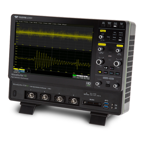
WaveSurfer 4000HD Oscilloscopes Operator's Manual Overview Front of Oscilloscope A. Touch screen display E. Mixed Signal interface B. Front panel controls F. USB 3.1 Gen 1 ports (2) C. Standby Power button G. Ground and Cal Out terminals D. ProBus analog inputs (4) H. - Page 9 Oscilloscope Overview and Set Up Back of Oscilloscope A. Wave Source output F. HDMI out (to external monitor) B. Kensington lock G. Ethernet (LAN) port C. Micro SD card (removable drive) H. USBTMC port D. EXT trigger input I. USB 2.0 ports (2) E.
- Page 10 WaveSurfer 4000HD Oscilloscopes Operator's Manual Front Panel Front panel controls duplicate functionality available through the touch screen and are described here only briefly. Knobs on the front panel function one way if turned and another if pushed like a button. The first label describes the knob’s “turn” action, the second label its “push”...
- Page 11 Oscilloscope Overview and Set Up Single starts Single trigger mode (single-shot acquisition). The first press arms the oscilloscope to trigger. The second press triggers the oscilloscope once when the triggering signal meets the trigger conditions. Stop prevents the scope from triggering on a signal. If you boot up the instrument with the trigger in Stop mode, a "No trace available"...
- Page 12 Push either knob to return to the default setting. Signal Interfaces Teledyne LeCroy instruments offer a variety of interfaces to input analog or digital signals. See the oscilloscope product page at teledynelecroy.com for a list of compatible input devices.
- Page 13 Active Probes Teledyne LeCroy offers a variety of active probes for use with your oscilloscope. Most active probes match probe to oscilloscope response automatically using probe response data stored in an on-board EEPROM. This ensures the best possible combined probe plus oscilloscope channel frequency response without the need to perform any de-embedding procedure.
-
Page 14: Powering On/Off
WaveSurfer 4000HD Oscilloscopes Operator's Manual Powering On/Off Press the Power button to turn on the instrument. To power down, you can quickly press the Power button again, but the safest way to power down is to use the File > Shutdown menu option, which will always execute a proper shut down process and preserve settings. -
Page 15: Connecting To Other Devices/Systems
Oscilloscope Overview and Set Up Connecting to Other Devices/Systems After start up, configure the oscilloscope connections using the menu options listed below. The oscilloscope is preset to accept DHCP network addressing over a TCPIP connection. Connect an Ethernet cable from the port on the back panel to a network access device. Go to Utilities >... -
Page 16: Configuring The Save/User Button
WaveSurfer 4000HD Oscilloscopes Operator's Manual External Device (for Waveform Generation) Connect a BNC cable from the WaveSource Output on the back of the instrument to the device to which you wish to output a signal. Go to Utilities > WaveSource to configure the signal. Note: WaveSource is optional and requires an activated license key. -
Page 17: Using Maui
Using MAUI Using MAUI MAUI (Most Advanced User Interface) is Teledyne LeCroy's unique oscilloscope user interface. Touch Screen The oscilloscope features a capacitive touch screen that supports fluid, tablet-like response to gestures. Note: Use your finger or a capacitive stylus (not included) to interact with the touch screen. A regular stylus will not work. - Page 18 WaveSurfer 4000HD Oscilloscopes Operator's Manual Grids The grids display the waveform traces. Every grid is 8 vertical divisions representing the full number of vertical levels and 10 horizontal divisions. The value represented by each division depends on the Vertical and Horizontal Scale of the traces that appear on the grid. The grid region can be divided up to three times to show channel (Cn), math (Fn), and zoom (Zn) traces on different grids.
- Page 19 Using MAUI Descriptor Boxes Trace descriptor boxes appear just beneath the grid whenever a trace is turned on. They function to: Inform—descriptors summarize the current trace settings and its activity status. Navigate—touch the descriptor box once to activate the trace, twice to open the setup dialog. Configure—drag-and-drop descriptor boxes to change source or copy setups (with OneTouch).
- Page 20 WaveSurfer 4000HD Oscilloscopes Operator's Manual Dialogs Dialogs appear at the bottom of the display for entering setup data. The top dialog will be the main entry point for the selected functionality. For convenience, related dialogs appear as a series of tabs behind the main dialog.
- Page 21 Message Bar At the bottom of the oscilloscope display is a narrow message bar. The current date and time are shown at the far right. Status, error, or other messages are shown at the far left, where "Teledyne LeCroy" normally appears.
-
Page 22: Maui With Onetouch
WaveSurfer 4000HD Oscilloscopes Operator's Manual MAUI with OneTouch Gestures like touch, drag and swipe can be used to create and change setups with one touch. Just as you change the display by using the setup dialogs, you can change the setups by moving different display objects. - Page 23 Using MAUI Copy Setups To copy the setup of one trace to another of the same type (e.g., channel to channel, math to math), drag- and-drop the source descriptor box onto the target descriptor box. To copy the setup of a measurement (Pn), drag-and-drop the source column onto the target column of the Measure table.
- Page 24 WaveSurfer 4000HD Oscilloscopes Operator's Manual Position Cursors To change cursor measurement time/level, drag cursor markers to new positions on the grid. The cursor readout will update immediately. To place horizontal cursors on zooms or other calculated traces where the source Horizontal Scale has forced cursors off the grid, drag the cursor readout from below the Timebase descriptor to the grid where you wish to place the cursors.
- Page 25 Using MAUI Store to Memory To store a trace to internal memory, drag-and-drop its trace descriptor box onto the target memory (Mn) descriptor box. Scroll To scroll long lists of values or readout tables, swipe the selection dialog or table in an up or down direction.
- Page 26 WaveSurfer 4000HD Oscilloscopes Operator's Manual Zoom To create a new channel zoom trace, touch then drag diagonally to draw a rectangle around the portion of the trace you want to zoom. Touch the Zn descriptor box to open the zoom factor controls and adjust the zoom exactly.
-
Page 27: Controlling Traces
Using MAUI Controlling Traces Traces are the visible representations of waveforms that appear on the display grid. They may show live inputs (Cn, Digitaln), a math function applied to a waveform (Fn), a stored memory of a waveform (Mn), a zoom of a waveform (Zn), or the processing results of special analysis software. - Page 28 WaveSurfer 4000HD Oscilloscopes Operator's Manual Turning On/Off Traces Turn On/Off Analog Trace To turn on a channel trace, do any of the following: From the front panel, press the Channel button. From the touch screen, choose Vertical > Channel n Setup. Touch the Add New box and select Channel, or drag another Cn descriptor box to Add New.
- Page 29 Using MAUI Labeling Traces The Label function gives you the ability to add custom annotations to the trace display. Once placed, labels can be moved to new positions or hidden while remaining associated with the trace. Create Label 1. Select Label from the context menu, or touch the Label Action toolbar button on the trace setup dialog.
-
Page 30: Zooming
WaveSurfer 4000HD Oscilloscopes Operator's Manual Zooming Zooms magnify a selected region of a trace by altering the horizontal and/or vertical scale relative to the source trace. Zooms may be created in several ways, using either the front panel or the touch screen. You can adjust zooms the same as any other trace by using the front panel Vertical and Horizontal knobs or the touch screen zoom factor... - Page 31 Using MAUI Zn Dialog Each Zn dialog reflects the center and scale for that zoom. Use it to adjust each zoom independently. Trace Controls Trace On shows/hides the zoom trace. It is selected by default when the zoom is created. Source lets you change the source of the zoom to any digital, math or memory trace while maintaining all other settings.
- Page 32 WaveSurfer 4000HD Oscilloscopes Operator's Manual Creating Zooms Any type of trace can be zoomed by creating a new zoom trace (Zn) following the procedures here. All zoom traces open in the same grid, with the zoomed portion of the source trace left unshaded. Zoomed area of source trace left unshaded.
- Page 33 Using MAUI Close Zoom New zooms are turned on and visible by default. If the display becomes too crowded, you can close a particular zoom and the zoom settings are saved in its Zn slot, ready to be turned on again when desired. To close the zoom, clear the Trace On box on the Zoom or Zn dialog.
- Page 34 WaveSurfer 4000HD Oscilloscopes Operator's Manual...
-
Page 35: Acquisition
Acquisition Acquisition The acquisition settings include everything required to produce a visible trace on screen and an acquisition record that may be saved for later processing and analysis: Vertical axis scale at which to show the input signal, and probe characteristics that affect the signal Horizontal axis scale at which to represent time, sampling mode and sampling rate Acquisition... -
Page 36: Vertical
Full vertical setup is done on the Cn dialog. To access it, choose Vertical > Channeln Setup from the menu bar, or touch the Channel descriptor box. If a Teledyne LeCroy probe is connected, its Probe dialog appears to the right of the Cn dialog. - Page 37 When a Teledyne LeCroy probe is connected to a channel input, the Attenuation field becomes a button to access the Probe dialog, a tab added to the right of the Cn tab. Enter Attenuation on the Probe dialog.
- Page 38 Auto Zero corrects for DC offset drifts that naturally occur from thermal effects in the amplifier of active probes. Teledyne LeCroy probes incorporate Auto Zero capability to remove the DC offset from the probe's amplifier output to improve the measurement accuracy.
-
Page 39: Digital (Mixed Signal)
Acquisition Digital (Mixed Signal) When a Mixed Signal device is connected to the oscilloscope, digital input options are added to the Vertical menu. There are set up dialogs for each possible digital group, Digital1 to Digitaln, which correspond to digital buses. You choose which lines make up each digital group, what they are named, and how they appear on the display. - Page 40 WaveSurfer 4000HD Oscilloscopes Operator's Manual Digital Setup Using Digital Leadset The digital leadset enables input of up-to-16 lines of digital data. Physical lines can be preconfigured into different logical groups, Digitaln, corresponding to a bus. The transitions for each line may be viewed through different displays.
- Page 41 Acquisition 4. When you're finished on the Digitaln dialog, open Logic Setup and choose the Logic Family that applies to each digital bank, or set custom Threshhold values. Digital Display Setup Choose the type and position of the digital traces that appear on screen for each digital group. 1.
- Page 42 WaveSurfer 4000HD Oscilloscopes Operator's Manual Renumbering Digital Lines Labels can also be "swapped" between lines. This procedure helps in cases where the physical lead number is different from the logical line number you would like to assign to that input. It can save time having to reattach leads or reconfigure groups.
-
Page 43: Timebase
Acquisition Timebase Timebase (Horizontal) settings control traces along the X axis. The timebase is shared by all channels. The time represented by each horizontal division of the grid, or Time/Division, is most easily adjusted using the front panel Horizontal knob. Full Timebase set up is done on the Timebase dialog, accessed either by choosing Timebase >... - Page 44 WaveSurfer 4000HD Oscilloscopes Operator's Manual Memory Maximum Points is the maximum number of samples taken per acquisition. The actual number of samples acquired can be lower due to the other timebase settings. The oscilloscope will allot the maximum memory and sample rate possible based on the activity within each pair of channels.
- Page 45 Acquisition Note: RIS is not available when the oscilloscope is using another form of digital interleaving. Roll Sampling Mode Roll mode displays incoming points of slow timebase acquisitions so that the trace appears to "roll" continuously across the screen from right to left. The acquisition is complete when a trigger event is detected, at which point the next acquisition begins immediately.
- Page 46 WaveSurfer 4000HD Oscilloscopes Operator's Manual Note: While optional, Timeout ensures that the acquisition completes in a reasonable amount of time and control is returned to the operator/controller without having to manually stop the acquisition, making it especially useful for remote control applications. 4.
- Page 47 Acquisition History Mode History Mode allows you to review any acquisition saved in the history buffer, which automatically stores all acquisition records until full. Not only can individual acquisitions be restored to the grid, you can "scroll" backward and forward through the history at varying speeds to capture changes in the waveforms over time.
- Page 48 WaveSurfer 4000HD Oscilloscopes Operator's Manual Top row buttons scroll: Fast Backward, Slow Backward, Slow Forward, Fast Forward. Bottom row buttons step: Back to Start, Back One, Go to Index (row #), Forward One, Forward to End. Press Pause when you see something of interest, then use the History table to find the exact Index. Select Single Acquisition 1.
-
Page 49: Trigger
Acquisition Trigger Triggers define the event around which digitized information is displayed on the grid. Different Trigger Types are used to select different events in the trigger source waveforms: edge voltages, pulse widths, high/low states, etc. These may be a single channel event or a complex pattern of events across several channels. - Page 50 WaveSurfer 4000HD Oscilloscopes Operator's Manual Trigger Types The Trigger Type sets the triggering conditions. Edge triggers upon a achieving a certain voltage level in the positive or negative slope of the waveform. Width triggers upon finding a positive- or negative-going pulse width when measured at the specified voltage level.
- Page 51 Acquisition Trigger Set Up To open the Trigger dialog, press the front panel Trigger Setup button or touch the Trigger descriptor box. Different controls will appear depending on the Trigger Type selected (e.g., Slope for Edge triggers). Complete the settings shown after making your selection. The trigger condition is summarized in a preview window at the far right of the Trigger dialog.
- Page 52 WaveSurfer 4000HD Oscilloscopes Operator's Manual Conditions (Smart Triggers) Smart triggers all allow you to apply Boolean logic to refine the triggering condition beyond simply Level and Slope/Polarity. The values that satisfy the operators of Less Than, Less Than or Equal To, Greater Than, etc. can be set by entering an Upper Value and/or Lower Value.
- Page 53 Acquisition 4. To set a Time Condition in which the pattern must occur once the trigger is armed, choose the operator: Less Than to trigger only if the pattern occurs before the time set. Greater Than to trigger only if the pattern occurs after the time set. In Range to set a time window in which the pattern must occur.
- Page 54 WaveSurfer 4000HD Oscilloscopes Operator's Manual Any Time triggers if B occurs any time after being qualified by A. Less Than triggers only if B occurs before the time set once qualified. Greater Than triggers only if B occurs after the time set once qualified. As with regular Holdoff, the counter may begin from the Acquisition Start or the Last Trigger Time.
- Page 55 Acquisition Positive Edge trigger with Holdoff by time counted from the last trigger time. Note: Because there is only one trigger per acquisition, the trigger event will always belongs to the new acquisition. The processing time shown here is for purposes of illustration only. Regardless of where in the acquisition record the trigger event was found (first edge or last), the display will show time pre- and post-trigger based on your Time/Div and Delay settings.
- Page 56 WaveSurfer 4000HD Oscilloscopes Operator's Manual Holdoff Set Up To add Holdoff to an Edge or Pattern trigger, touch the Trigger descriptor box or press the front panel Trigger Setup button, then open the Holdoff tab. Choose to Holdoff by Time (the clock) or Events. If using Holdoff by Time, enter the Time in S to wait before triggering.
-
Page 57: Display
Display Display Display settings affect the number and style of grids that appear on screen and some of the visual characteristics of traces, such as persistence. Auto Grid is enabled by default. This feature divides the screen as needed when new traces open. WaveSurfer oscilloscopes may be divided into a maximum of three grids—one each for channels/memories, math functions, and zooms—that each represent the full number of vertical levels. -
Page 58: Persistence Display
WaveSurfer 4000HD Oscilloscopes Operator's Manual Trace Choose a line style for traces: solid Line or disconnected sample Points. When more data is available than can actually be displayed given the number of vertical levels, Trace Intensity helps to visualize significant events by applying an algorithm that dims less frequently occurring samples. - Page 59 Display Apply Persistence 1. Check Persistence On. 2. Use the buttons to select a persistence mode: In Analog Mode, as a persistence data map develops, different intensities of the same color are assigned to the range between a minimum and a maximum population.
- Page 60 WaveSurfer 4000HD Oscilloscopes Operator's Manual...
-
Page 61: Cursors
Cursors Cursors Cursors are markers (lines, cross-hairs, and arrows) that identify horizontal and vertical values where they intersect the X or Y axis. Use cursors to make fast, accurate measurements of points on the waveform. Cursor Types Horizontal Cursors Horizontal cursors are positioned at points on the x-axis and will measure the source trace horizontal and vertical values at that point. - Page 62 WaveSurfer 4000HD Oscilloscopes Operator's Manual When horizontal cursors are not tracking, they can be moved to any position along the x-axis individually. The horizontal delta represents X2 – X1, which will be a positive number so long as X2 remains to the right of X1.
-
Page 63: Apply And Position Cursors
Cursors Apply and Position Cursors To turn on cursors, either: From the menu bar, choose Cursors and select the desired cursor type from the drop-down list. On the front panel, press the Cursor button to turn on cursors, then continue pressing to cycle through all the cursor types. -
Page 64: Standard Cursors Dialog
WaveSurfer 4000HD Oscilloscopes Operator's Manual Standard Cursors Dialog These controls can be used instead of the front panel controls to turn on cursors or to refine the cursor position. Access the dialog by choosing Cursors > Cursors Setup from the menu bar. Cursor Type buttons select the type of cursor displayed on the grid. -
Page 65: Measure
Measure Measure Parameters are tools that give you access to a wide range of waveform properties, such as Rise Time, RMS voltage and Peak-Peak voltage. Parameter readouts are shown in a dynamic Measure table that appears below the waveform grids. All active measurements can be used as inputs to other processes, such as math functions, even when the Measure table is hidden from view. -
Page 66: Parameter Set Up
WaveSurfer 4000HD Oscilloscopes Operator's Manual Parameter Set Up The Measure Dialog gives quick access to measurement features. Besides configuring parameters, use the Measure dialog to show statistics and histicons, or to gate measurements. 1. To open the Measure dialog, touch the Add New box and select Measurement, or choose Measure >... - Page 67 Measure on the Measure dialog. All parameters share the same gates, and all measurements will change when you drag either gate post to reposition the gate. Touch Default to return the gates to the width of the grid. Statistics and Histicons Checking Statistics On on the Measure dialog adds the mean, min, max and sdev of each parameter to the measured value shown on the Measure table.
-
Page 68: List Of Standard Measurements
WaveSurfer 4000HD Oscilloscopes Operator's Manual List of Standard Measurements Note: Unless otherwise stated, measurements are calculated according to IEEE standards. Additional measurements may be available depending on the software options installed. Amplitude Difference between the upper and lower levels in two-level (bi-modal) signals. Differs from Peak-to-Peak (pkpk) in that noise, overshoot, undershoot, and ringing do not affect the measurement. - Page 69 Measure Reciprocal of each Period of a cyclic signal. Period is measured as time between every pair of 50% crossings on the rising edge, starting with the first rising transition after the left measurement gate. Maximum Largest vertical value in a waveform. Unlike Top, does not assume the waveform has two levels. Mean Average of vertical values in a waveform.
- Page 70 WaveSurfer 4000HD Oscilloscopes Operator's Manual Duration of a pulse waveform's rising transition from 10% to 90% of amplitude, averaged for all rising transitions between the measurement gates. On signals that do not have two major levels (such as triangle waves), the Top-Base measurement used to calculate rise can default to maximum and minimum, giving less predictable results.
-
Page 71: Using Trends
Measure Using Trends The Trend math function plots a waveform composed of parameter measurements arranged in the order the measurements were made. The vertical units are the source parameter values, and the horizontal unit is the measurement number. The Trend contains a single value for each unique measurement, and therefore may not be time synchronous with the source waveform, where the same measured value may occur successively over time. - Page 72 WaveSurfer 4000HD Oscilloscopes Operator's Manual...
-
Page 73: Math
Math Math Math function traces (Fn) display the result of applying a mathematical operation to a source trace. The output of a math function is always another trace, whereas the output of a measurement parameter is a tabular readout of the measurement. Math can be applied to any channel (Cn), zoom (Zn), or memory (Mn) trace. -
Page 74: Math Dialog
WaveSurfer 4000HD Oscilloscopes Operator's Manual A Summary of the function you are building appears on the dialog. Refer to this to be sure your sources are in the proper order to yield the function you want (e.g., C1-C2 vs. C2-C1). 4. -
Page 75: List Of Standard Math Operators
Math List of Standard Math Operators Note: The installation of software options on the oscilloscope may add math operators to this list. Absolute Calculates distance away from zero for every point in the waveform. For values greater than zero, this is the same as the value. - Page 76 WaveSurfer 4000HD Oscilloscopes Operator's Manual Each calculated area is summed with the previous sum of areas. The multiplier and adder are applied before the integration function. Invert For every point in the waveform, the inverse of that point is calculated. Product For every point in the waveform, the value of Source1 is multiplied by the value of Source 2.
-
Page 77: Average Function
Math Average Function The summed or continuous average of all data samples from multiple acquisitions can be displayed as a new waveform trace using the Average function. Setting Up Averaging To apply Continuous or Summed Averaging as a Math function: 1. -
Page 78: Eres Function
WaveSurfer 4000HD Oscilloscopes Operator's Manual Sweep New Average = 1 (no old average yet) (new data +0 * old average)/(0 + 1) = new data only (new data + 1*old average)/(1 + 1) = 1/2 new data +1/2 old average (new data + 2 * old average)/(2 + 1) = 1/3 new data + 2/3 old average (new data + 3 * old average)/(3 + 1) = 1/4 new data + 3/4 old average (new data + 4 * old average)/(4 + 1) = 1/5 new data + 4/5 old average... - Page 79 Math Resolution Increase -3 dB Bandwidth (x Nyquist) Filter Length (Samples) 0.241 0.121 0.058 0.029 0.016 With low-pass filters, the actual SNR increase obtained in any particular situation depends on the power spectral density of the noise on the signal. The improvement in SNR corresponds to the improvement in resolution if the noise in the signal is white (evenly distributed across the frequency spectrum).
-
Page 80: Fft Function
WaveSurfer 4000HD Oscilloscopes Operator's Manual FFT Function For a large class of signals, you can gain greater insight by looking at spectral representation rather than time description. Signals encountered in the frequency response of amplifiers, oscillator phase noise and those in mechanical vibration analysis, for example, are easier to observe in the frequency domain. If sampling is done at a rate fast enough to faithfully approximate the original waveform (usually five times the highest frequency component in the signal), the resulting discrete data series will uniquely describe the analog signal. - Page 81 Math Window Type Applications and Limitations Rectangular Normally used when the signal is transient (completely contained in the time-domain window) or known to have a fundamental frequency component that is an integer multiple of the fundamental frequency of the window. Signals other than these types will show varying amounts of spectral leak- age and scallop loss, which can be corrected by selecting another type of window.
-
Page 82: Rescale Function
WaveSurfer 4000HD Oscilloscopes Operator's Manual Rescale Function The Rescale function allows you to create a new function trace that rescales another trace by applying a multiplication factor (a) and additive constant (b). You can also use it as a way to view the function source in a different unit of measure. - Page 83 Math Note: Time and dimensionless units are available only for certain measurements and for use in code where relevant. Category Unit Mnemonic Mass gram slug SLUG Volume liter cubic meter cubic inch cubic foot cubic yard YARD3 Angle radian arcdegree arcminute arcsecond cycle...
- Page 84 WaveSurfer 4000HD Oscilloscopes Operator's Manual Category Unit Mnemonic Pressure Pascal atmosphere, technical atmosphere, standard Torr TORR pounds/square inch Temperature degrees Kelvin degrees Celsius degrees Fahrenheit Energy Joule British Thermal Unit calorie Rotating Machine radians/second RADPS frequency (Hertz) revolutions/second revolutions/minute torque N•m torque in•oz INOZ torque in•lb...
- Page 85 Math Category Unit Mnemonic Electrical Ampere Volt Watt power, apparent power, reactive power factor capacitance (Farad) Coulomb Siemen electrical field strength electrical displacement field CPM2 permittivity FARADPM conductivity SIEPM Time second minute hour HOUR week WEEK...
- Page 86 WaveSurfer 4000HD Oscilloscopes Operator's Manual Category Unit Mnemonic Dimensionless percent percent min-max PCTMNMX decibel decibel milliwatt decibel Volt decibel millivolt DBMV decibel microvolt DBUV decibel microampere DBUA decibel referred to carrier decade DECADE unit interval Q-scale byte BYTE baud BAUD least significant bit poise POISE...
-
Page 87: Memory
Save (External) Waveform Files to Memory Trace (.trc) files saved on other Teledyne LeCroy instruments can also be saved to internal memory. Use the Recall Waveform function to save external files to memory. Then, you can use the Memories dialog to... -
Page 88: Restoring Memories
WaveSurfer 4000HD Oscilloscopes Operator's Manual restore them to the touch screen. Note: The removable MicroSD card serves as internal memory for saving .trc files. Restoring Memories The Memories dialog is a convenient panel for restoring saved memories to the display. Access the Memories dialog by choosing Math >... -
Page 89: Analysis Tools
Analysis Tools Analysis Tools The Analysis menu tools complement the standard math and measurements to help you understand the behavior of waveforms. WaveScan searches single or multiple acquisitions for events that meet specific criteria. Pass/Fail Testing shows whether waveforms meet mask test limits. Optional software packages may be purchased for specialized uses, such as power analysis. - Page 90 WaveSurfer 4000HD Oscilloscopes Operator's Manual Setting Up WaveScan Set up your source channel and triggers before setting up the scan. 1. Press the front panel Stop button to stop acquisition. 2. Choose Analysis > WaveScan and check Enable. 3. Choose the Source waveform. 4.
- Page 91 Analysis Tools Non-monotonic Mode Non-monotonic Mode looks for edges that cross a threshold more than once between high and low levels. All events that meet the criteria of slope, hysteresis, and level are presented in a table and highlighted in the source trace.
- Page 92 WaveSurfer 4000HD Oscilloscopes Operator's Manual Bus Pattern Mode Bus Pattern Mode (only on Mixed Signal models) is used for finding 2- to 16-bit patterns across the digital lines. Bus Pattern Mode settings are: Viewing. Choose to enter the pattern as Binary or Hex(adecimal). Binary/Hex.
-
Page 93: Pass/Fail Testing
Analysis Tools PASS/FAIL Testing PASS/FAIL testing is a type of mask testing that is particularly useful for comparing newly acquired signals to a previously acquired "golden standard" waveform. The software counter will update in real time as new acquisitions are compared to the mask, and colored markers will quickly show those areas of the waveform that violate the mask. - Page 94 WaveSurfer 4000HD Oscilloscopes Operator's Manual Load Mask Use this procedure in lieu of Make Mask if you have a pre-defined mask file. 1. Open the Load Mask subdialog. 2. Touch File and select the mask. 3. Check View Mask to display the mask over the trace. Remove a Mask from the Display Touch the Delete Mask button at the left of the Pass/Fail dialog.
-
Page 95: Saving Data (File Functions)
Note: Only traces saved in Teledyne LeCroy proprietary formats can be recalled to the display directly. Use the Binary format (.trc) for analog waveforms, or WaveML (.xml) for digital waveforms. - Page 96 3. Choose the Source waveform. To quickly save all displayed waveforms separate trace files, touch the All Displayed button. 4. Select a file Format. Binary is Teledyne LeCroy's .trc file format. Binary results in the smallest possible file size. Binary files can be converted to ASCII using Teledye LeCroy utilities such as WaveStudio.
- Page 97 Saving Data (File Functions) Save Setup You can quickly save oscilloscope configurations to one of the internal setup panels or to a LeCroy System Setup (.lss) file, a text-based Automation program. Setups can be easily recalled to restore the oscilloscope to the saved state. Save Setup to Memory 1.
- Page 98 WaveSurfer 4000HD Oscilloscopes Operator's Manual Save Table The Save Table function saves tabular measurement data displayed on screen to an Excel or ASCII file. 1. From the menu bar, choose File > Save, then choose Table. 2. To save only one of the tables displayed, touch Source and navigate to the selection. By default, data from all visible tables are saved to separate files.
- Page 99 Saving Data (File Functions) Save Screen Image The full touch screen display or selected portions of it can be captured, saved to an image file, and marked with custom annotations. 1. From the menu bar, choose File > Save, then choose Screen Image. 2.
- Page 100 WaveSurfer 4000HD Oscilloscopes Operator's Manual Auto Save Data that appears on the oscilloscope display, such as waveforms, measurement readouts and decoder data, can be very dynamic and difficult to read from the oscilloscope unless you stop the acquisition. Auto Save enables you to automatically store waveform and table data to file with each new trigger. The file can later be recalled to the oscilloscope or saved permanently to external storage.
-
Page 101: Recall
Setups saved to internal memory or to .LSS file can be recalled to restore the oscilloscope to the saved state. Waveform data stored in Teledyne LeCroy binary (.trc) or WaveML (.xml) format can be recalled directly to the display. Waveform data stored in other binary or ASCII file formats can be recalled into a memory and from there displayed. - Page 102 WaveSurfer 4000HD Oscilloscopes Operator's Manual Recall Setup Choose File > Recall Setup... from the menu bar. Recall Setup from Memory 1. Choose to Recall From Memory. 2. Touch one of the six Recall buttons under Recall From Internal Setup..Note: If a setup has been stored to a location, it is labeled with the save date/time. Otherwise, the slot is labeled Empty.
-
Page 103: Labnotebook
Saving Data (File Functions) LabNotebook The LabNotebook feature allows you to create and save composite files containing a screen capture of all displayed waveforms, as well as all waveform and setup data at the time of capture. The Flashback feature instantly recalls the setups and waveforms stored with LabNotebook Entries, enabling you to restore the exact state of the instrument at a later date to perform additional analysis. - Page 104 WaveSurfer 4000HD Oscilloscopes Operator's Manual 6. If you do not want to use autonumbering to identify files, deselect Counter. 7. Touch Save Now. 8. If annotating, use the Drawing toolbar to mark up the screen image. Click Done when finished. Recall LabNotebook Once a LabNotebook Entry is saved, you can either: Recall the screen image to view and modify descriptive information, or manage attachments and...
- Page 105 Saving Data (File Functions) 3. From the top of the preview window, choose Manage Attachments and select the files to attach. The file list will build in the lower part of the File Attachments browser. 4. Click Update Attachments to finish. To later remove appended files, click Manage Attachments and deselect the files from the list.
-
Page 106: Share
WaveSurfer 4000HD Oscilloscopes Operator's Manual Persistence data, although it is saved with the .LNB file and appears on reports. Histogram data over 16-bits. Floating point waveforms resulting from certain math operations that have much higher resolution than 16-bits. This extra resolution is not preserved when traces are recalled using Flashback. Cumulative Measurements in process when Flashback is entered. -
Page 107: Email & Report Settings
Saving Data (File Functions) Email & Report Settings Configure oscilloscope email settings and report output on the Email & Report Settings dialog. Note: If using MAUI Studio Pro, these email settings can be pushed to a connected oscilloscope, but they will not affect email on your PC. The report settings apply to reports created from LabNotebook files or the current state of a connected oscilloscope. -
Page 108: Print
WaveSurfer 4000HD Oscilloscopes Operator's Manual Print Print captures an image of the touch screen display and sends it to a printer formatted according to your selections here. These settings also apply wherever you have a Print Screen option on a dialog. The Print Now button at the far right of the dialog can be used to execute your current Print selection. -
Page 109: Using The File Browser
Saving Data (File Functions) Using the File Browser Selecting Browse on any of the File menu dialogs opens a File Browser that enables you to perform basic disk utility functions, as well as making file path/name and format selections. Disk Utilities New Folder, Delete Folder, Delete File, and Delete All Files can be used to change your file system prior to saving new files. - Page 110 WaveSurfer 4000HD Oscilloscopes Operator's Manual Auto Naming Selections The checkboxes to turn on/off the Source prefix and the Counter number suffix used to autogenerate file names will appear on the File Browser when saving files. These selections are linked to those on the underlying dialog, and changing the value in either place causes it to change everywhere.
-
Page 111: Utilities
The Service button to the far right of the dialog launches a section of the application reserved for qualified Teledyne LeCroy service personnel. An access code is required to enter this section. Status The Utilities Status dialog displays information about your instrument including model number, serial number, firmware version, and installed hardware and software options. - Page 112 The Remote dialog contains settings to configure remote control of the instrument and also network access. Supported remote control protocols are: TCPIP (Ethernet). If you choose this option for remote control, also install Teledyne LeCroy's VICP drivers on the controller. These are included in the VICP Passport plug-in, available free from the software download page at teledynelecroy.com...
- Page 113 Utilities oscilloscope should connect to the network seamlessly; you do not need to re-enter credentials unless you wish to change them. Note: These may be the credentials of any valid domain user (e.g., your own logon); they do not have to be unique to the oscilloscope. Consult with your Network Administrator. 1.
- Page 114 WaveSurfer 4000HD Oscilloscopes Operator's Manual Date/Time Date/Time settings control the instrument's timestamp. These numbers appear in the message bar and on tables/records internal to the oscilloscope application, such as History Mode and WaveScan. Note: On Windows 10 oscilloscopes, first switch to the Admin User LCRYADMIN to change the Date/Time settings.
- Page 115 Utilities Options Many optional software packages are available to extend the Analysis functions of the instrument. When you purchase an option, you will receive a key code by email that activates the new functionality. Use the Options dialog to activate software options by installing the key code. This dialog also displays the ScopeID and Serial #.
-
Page 116: Disk Utilities
WaveSurfer 4000HD Oscilloscopes Operator's Manual Disk Utilities Use the Disk Utilities dialog to manage files and folders on your instrument's hard drive. Disk Space information is shown at the far right of the dialog for convenience. Access the Disk Utilities dialog by selecting Utilities > Disk Utilities from the menu bar. Using the File Browser Touch Launch File Browser to display the same dialog as used for managing files when saving/recalling waveforms, setups or LabNotebooks. -
Page 117: Preferences Dialogs
Utilities Preferences Dialogs Preference settings have mostly to do with the appearance and performance of the instrument itself, rather than its interaction with other devices/systems. These settings are called "non-volatile," because they are not lost when the oscilloscope is restarted and do not change when a setup panel is recalled. Access the Preferences dialogs by choosing Utilities >... - Page 118 WaveSurfer 4000HD Oscilloscopes Operator's Manual Calibration To ensure the instrument maintains specified performance, it is factory set to perform a calibration during warm-up. We recommend that you warm up the oscilloscope for at least 20 minutes prior to use to give the instrument time to complete calibration procedures.
- Page 119 Utilities Acquisition The Acquisition preference settings determine how traces behave as Vertical Offset or Horizontal Delay changes. Choose Utilities > Preference Setup to open the Acquisition dialog. Offset Setting constant in: Volts keeps the amount of Offset in the amount of Volts specified, regardless of the V/div setting. As the Offset is adjusted, the trace will appear to move up or down relative to the zero level.
- Page 120 Miscellaneous These other Preference settings are located on the Miscellaneous dialog. To add the Teledyne LeCroy logo to print output, check Print Teledyne LeCroy Logo When Printing Grid Area Only. This identifies the instrument as the source of the image.
-
Page 121: Wavesource Automatic Waveform Generator
Utilities WaveSource Automatic Waveform Generator The WaveSource Automatic Waveform Generator allows you to output custom sine, square, triangle, pulse, DC, noise, and arbitrary waveforms from the oscilloscope. Connect a BNC cable from the WaveSource output on the back of the oscilloscope to the external device. Output is continuous once WaveSource is enabled. - Page 122 WaveSurfer 4000HD Oscilloscopes Operator's Manual 4. Touch Browse next to the File Name field and browse to the location of the arbitrary waveform file on either the Storage Card or the USB Disk. Select the file and touch OK. 5. Touch Upload. 6.
-
Page 123: Digital Voltmeter
Utilities Digital Voltmeter The Digital Voltmeter option activates an integrated 4-digit digital voltmeter and 5-digit frequency counter that operates through the same probes already attached to the oscilloscope channels. Use it to view real- time measurements through a dedicated user interface display that continues even when your triggering system is stopped. - Page 124 WaveSurfer 4000HD Oscilloscopes Operator's Manual Set Up DVM 1. From the menu bar, choose Utilities > DVM. 2. Mark Enable to turn on the DVM function. 3. Touch Source and select the input channel to be measured. 4. Touch Mode and choose the waveform parameter to display on the readout. Options are: DC RMS AC RMS Frequency...
-
Page 125: Maintenance
This procedure is only for oscilloscopes running the Microsoft Compact Embedded (CE) operating system. Teledyne LeCroy frequently releases free firmware updates containing new product features and bug fixes. The installer updates multiple components including the oscilloscope application, required DLLs, drivers, and low-level microcode for integrated circuits on the oscilloscope. - Page 126 WaveSurfer 4000HD Oscilloscopes Operator's Manual...
-
Page 127: Returning A Product For Service
3. Pack the instrument in its original shipping box, or an equivalent carton with adequate padding to avoid damage in transit. Do not include the manual. 4. Mark the outside of the box with the shipping address given to you by Teledyne LeCroy. Be sure to add the following: ATTN: <RMA code assigned by Teledyne LeCroy>... -
Page 128: Certifications
WaveSurfer 4000HD Oscilloscopes Operator's Manual Certifications Teledyne LeCroy certifies compliance to the following standards as of the time of publication. See the EC Declaration of Conformity document shipped with your product for the current certifications. EMC Compliance EC Declaration of Conformity- EMC The instrument meets the intent of EC Directive 2014/30/EU for Electromagnetic Compatibility. -
Page 129: Safety Compliance
Certifications AS/NZS CISPR 11:2015, Radiated and Conducted Emissions, Group 1, Class A USTRALIA EALAND ONTACTS RS Components Pty Ltd. RS Components Ltd. Suite 326 The Parade West Unit 30 & 31 Warehouse World 761 Great South Road Kent Town, South Australia 5067 Penrose, Auckland, New Zealand *Visit teledynelecroy.com/support/contact for the latest contact information. -
Page 130: Environmental Compliance
The product is subject to disposal and recycling regulations that vary by country and region. Many countries prohibit the disposal of waste electronic equipment in standard waste receptacles. For more information about proper disposal and recycling of your Teledyne LeCroy product, please visit teledynelecroy.com/recycle. -
Page 131: Warranty
The product is warranted for normal use and operation, within specifications, for a period of three years from shipment. Teledyne LeCroy will either repair or, at our option, replace any product returned to one of our authorized service centers within this period. However, in order to do this we must first examine the product and find that it is defective due to workmanship or materials and not due to misuse, neglect, accident, or abnormal conditions or operation. - Page 132 WaveSurfer 4000HD Oscilloscopes Operator's Manual...
-
Page 133: Index
Index Index compliance 124 cooling 2 acquisition coupling 8, 15, 33 pre-processing 15 cursor 57 sampling mode 39 controls 60 settings 115 readout 15 action toolbar 16 date and time 110 activating traces 23 de-embedding 9 altitude 2 default setup 98, 121 analog degauss 34 inputs 8... - Page 134 WaveSurfer 4000HD Oscilloscopes Operator's Manual file browser 105 inputs file structure 105 analog 8 filtering intensity bandwidth 33 grid 53 LabNotebook entries 105 interfaces 8 noise 74 ProBus 8 firmware 10 inversion 33 version 107 IP address 108 Flashback Recall 99-100 labelling traces 25 foreground trace 23 LabNotebook 13, 99...
- Page 135 Index memory 83-84, 91, 93 recall descriptor box 15 LabNotebooks 100 memory length 40 remote control 116 MicroSD card 112 removable hard drive 112 rescaling 78 offset 115 restore operating environment 2 waveforms 84 options 10, 111 returns 123 RH 2 parameter compare 89 RIS sampling mode 40 pass/fail testing 89...
- Page 136 WaveSurfer 4000HD Oscilloscopes Operator's Manual sequence sampling mode 41, 54 TRC files 83 service 122-123 trend 67 setup panels 93, 98-99 trigger 45 software options 10, 111 controls 45, 50 sound 113 counter 50, 115 support 122-123 delay 39 system descriptor box 15 on/off 10 holdoff 50...
- Page 137 ...-Ji� TELEDYNE LECROY Everywhereyoulook· ,."1111111 Test Equipment Depot - 800.517.8431 - 5 Commonwealth Ave, MA 01801 TestEquipmentDepot.com...