
Related Manuals for Vaisala HUMICAP MMT310


Summary of Contents for Vaisala HUMICAP MMT310
- Page 1 USER'S GUIDE Vaisala HUMICAP® Moisture and Temperature Transmitter Series for Oil MMT310 M210474EN-D...
- Page 2 English versions are applicable, not the translations. The contents of this manual are subject to change without prior notice. This manual does not create any legally binding obligations for Vaisala towards customers or end users. All legally binding obligations and agreements are included exclusively in the applicable supply contract or the General Conditions of Sale and General Conditions of Service of Vaisala.
-
Page 3: Table Of Contents
Ball Valve Installation Kit for MMT318 ........ 23 Sampling Cell for MMT318 ..........25 Mounting the MMT317 ............25 MMT317 Probe with Swagelok Connector for Tight-place Installations ..............26 Connections ................28 Cable Wiring ................ 28 Power Supply Requirements ..........29 CHAPTER 4 VAISALA _________________________________________________________________________ 3... - Page 4 User's Guide _______________________________________________________________________ OPERATION ....................31 Power Supply ................31 Transmitter Start-Up ............... 31 Serial Line and Analog Communication Options ....32 RS-232 Serial Port Connection ........... 32 USB Connection ..............33 Installing the Driver for the USB Cable ......33 Connection to an MI70 Hand-held Indicator ......
- Page 5 Calculation Model with Oil Specific Coefficients ....77 PPM Calculation Setting ............78 Calculation Setting (Calculation Model with Average Coefficients) ................ 78 Changing the Calculation Coefficients (Calculation Model with Oil Specific Coefficients) ..........78 Technical Data ............... 79 Paper Machine Application ........... 80 VAISALA _________________________________________________________________________ 5...
- Page 6 User's Guide _______________________________________________________________________ List of Figures Figure 1 MMT310 Transmitter Parts ............15 Figure 2 MMT310 Probes ............... 16 Figure 3 Mounting with Mounting Plates ..........18 Figure 4 Rain Shield with Large Mounting Plate ........19 Figure 5 MMT318 Probe ................. 20 Figure 6 Sealing of Fitting Body into Process .........
-
Page 7: Chapter 1 General Information
This chapter provides general notes for the manual and the MMT310. About This Manual This manual provides information for installing, operating, and ® maintaining Vaisala HUMICAP Moisture and Temperature Transmitter Series for Oil MMT310 (MMT317 and MMT318). Contents of This Manual... -
Page 8: Version Information
Related Manuals Table 2 Related Manuals Manual Code Manual Name M210878EN Vaisala HUMICAP® Hand-held Moisture Meter for Oil MM70 User’s Guide M210185EN Vaisala Humidity calibrator HMK15 User’s Guide Documentation Conventions Throughout the manual, important safety considerations are highlighted as follows: Warning alerts you to a serious hazard. -
Page 9: Safety
ESD Protection Electrostatic Discharge (ESD) can cause immediate or latent damage to electronic circuits. Vaisala products are adequately protected against ESD for their intended use. It is possible to damage the product, however, by delivering electrostatic discharges when touching, removing, or inserting any objects inside the equipment housing. -
Page 10: Recycling
EFT burst (Electric fast EN/IEC 61000-4-4 transients) Surge EN/IEC 61000-4-5 Conducted immunity EN/IEC 61000-4-6 Trademarks ® HUMICAP is a registered trademark of Vaisala. Windows® is a registered trademark of Microsoft Corporation in the United States and/or other countries. 10 ___________________________________________________________________ M210474EN-D... -
Page 11: Software License
Chapter 1 _________________________________________________________ General Information Software License This product contains software developed by Vaisala. Use of the software is governed by license terms and conditions included in the applicable supply contract or, in the absence of separate license terms and conditions, by the General License Conditions of Vaisala Group. - Page 12 User's Guide _______________________________________________________________________ This page intentionally left blank. 12 ___________________________________________________________________ M210474EN-D...
-
Page 13: Chapter 2 Product Overview
This chapter introduces the features, advantages, and the product nomenclature. Introduction to MMT310 Series ® The Vaisala HUMICAP Moisture and Temperature Transmitter Series for Oil MMT310 is a small-size oil moisture and temperature transmitter that powers up with 10 ... 35 VDC (mode-dependent power supply requirements). - Page 14 User's Guide _______________________________________________________________________ Vaisala HUMICAP moisture in oil transmitters MMT318 and MMT317 are designed for industrial applications. They measure water in oil in terms of water activity (aw) and relative saturation (%RS). With the help of internal oil solubility coefficients, MMT310 is also able to output oil moisture in ppm (by default supported only for mineral transformer oil).
-
Page 15: Mmt310 Transmitter Parts
1 = Transmitter unit 2 = Mounting plate (smaller mounting plate also available) 3 = Connector for signal output and power supply. Available with female connector with 5 m cable or screw terminal connector. 4 = Probe VAISALA ________________________________________________________________________ 15... -
Page 16: Probe Options
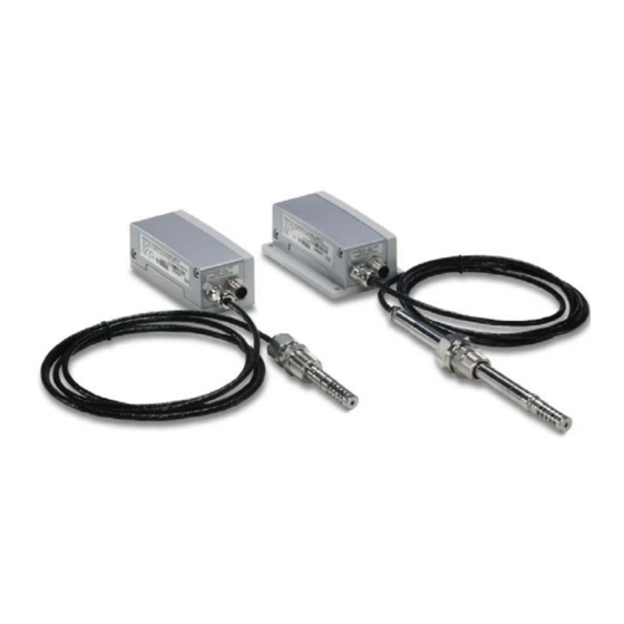
User's Guide _______________________________________________________________________ Probe Options 1311-199 Figure 2 MMT310 Probes The following numbers refer to Figure 2 above: 1 = MMT317 probe with optional Swagelok connector for tight-place installations. 2 = MMT318 probe for pressurized pipelines with two adjustable probe lengths and optional ball valve set. For probe dimensions, see MMT317 Probe with Optional Swagelok Connector, Dimensions on page 74 and MMT318 Probe Dimensions on page 72. -
Page 17: Chapter 3 Installation
Take care not to damage the pipe of the probe. If the pipe is damaged, NOTE the probe head is less tight and will not go through the clasp nut. Make sure that the filter is tightly fastened to protect the sensors. VAISALA ________________________________________________________________________ 17... -
Page 18: Mounting The Transmitter/Removing The Transmitter Unit
User's Guide _______________________________________________________________________ Mounting the Transmitter/Removing the Transmitter Unit Select a place with stable conditions for mounting the transmitter. Do not expose the transmitter to direct sunlight or rain. Always mount the transmitter housing with the cable bushings pointing downwards. If the transmitter is mounted outdoors, cover it with a shelter (purchased by NOTE customer). -
Page 19: Mounting The Transmitter With Optional Rain Shield
Mounting the Transmitter with Optional Rain Shield If you mount MMT310 outdoors, use a shelter to protect the transmitter. An MMT310 rain shield is available from Vaisala as an optional accessory (order code ASM211103). Vaisala does not recommend installing the transmitter outdoors with the NOTE smaller mounting plate (without flanges). -
Page 20: Mounting The Mmt318
User's Guide _______________________________________________________________________ You can mount the rain shield and transmitter directly to a wall with screws through both the mounting plate and the rain shield, or attach the transmitter mounting plate to the rain shield and use for example U-bolt mounting depending on the requirements of the installation site. -
Page 21: Tightening The Clasp Nut
Mark the fitting screw and the clasp nut. Tighten the nut a further 50 - 60º (ca. 1/6 turn) with a wrench. If you have suitable torque wrench, tighten the nut to max 45 ± 5 Nm (33 ± 4 ft-lbs). VAISALA ________________________________________________________________________ 21... -
Page 22: Figure 7 Tightening The Clasp Nut
User's Guide _______________________________________________________________________ 0505-276 Figure 7 Tightening the Clasp Nut The following numbers refer to Figure 7: 1 = Probe 2 = Clasp nut 3 = Fitting screw 4 = Pen (for marking) Take care not to overtighten the clasp nut to avoid difficulties when NOTE opening it. -
Page 23: Ball Valve Installation Kit For Mmt318
Chapter 3 ________________________________________________________________ Installation Ball Valve Installation Kit for MMT318 The optional ball valve installation kit (Vaisala order code: BALLVALVE-1) is preferred when connecting the probe to a pressurized process or pipeline. Use the ball valve set or a 1/2" ball valve assembly with a ball hole of Ø14 mm or more. - Page 24 User's Guide _______________________________________________________________________ The probe can be installed in the process through the ball valve NOTE assembly provided that the process pressure is less than 10 bars. This way, the process does not have to be shut down when installing or removing the probe.
-
Page 25: Sampling Cell For Mmt318
Using a bypass sampling line may be feasible in these cases. Sampling Cell with Swagelok Connectors (Vaisala order code: DMT242SC2) is available as an optional accessory. -
Page 26: Mmt317 Probe With Swagelok Connector For Tight-Place Installations
User's Guide _______________________________________________________________________ MMT317 Probe with Swagelok Connector for Tight- place Installations The Swagelok installation kit for MMT317 includes a Swagelok connector with ISO3/8" thread (Vaisala order code: SWG12ISO38) or NPT1/2" thread (Vaisala order code: SWG12NPT12). 0509-144 Figure 10 MMT317 Probe with Swagelok Installation Kit... - Page 27 1/4 turn (90º). Use teflon tape or thread sealant to seal the connection between the Swagelok connector and the process (see Figure 6 on page 21). VAISALA ________________________________________________________________________ 27...
-
Page 28: Connections
User's Guide _______________________________________________________________________ Connections When the MMT310 leaves the factory, the measurement ranges, output scaling and quantities have already been set according to the customer order. The unit is calibrated at the factory and ready for use. The transmitter is delivered with either a screw terminal connector or with a detachable 5m cable with eight wires for serial port, analog outputs and 10 …... -
Page 29: Power Supply Requirements
MMT310 can also be powered by an MI70 indicator or a USB cable connection to a computer. For information on ordering the optional MI70 and USB connection cables, see section Spare Parts and Accessories on page 69. VAISALA ________________________________________________________________________ 29... - Page 30 User's Guide _______________________________________________________________________ This page intentionally left blank. 30 ___________________________________________________________________ M210474EN-D...
-
Page 31: Operation
- In RUN mode a measurement output starts immediately. - In POLL mode the transmitter does not output anything after powerup. For instructions on configuring the serial mode, see section Set Serial Interface Mode on page 39. VAISALA ________________________________________________________________________ 31... -
Page 32: Serial Line And Analog Communication Options
USB), you need a terminal program to operate the MMT310 command line interface. For instructions on installing and using the PuTTY terminal application for Windows (available from http://www.vaisala.com/software), see section Terminal Program Settings on page 35. For information on using the analog outputs, see section Setting, Scaling and Testing the Analog Outputs on page 44. -
Page 33: Usb Connection
The installation has reserved a COM port for the cable. Verify the port number, and the status of the cable, using the Vaisala USB Device Finder program that has been installed in the Windows Start menu. -
Page 34: Connection To An Mi70 Hand-Held Indicator
User's Guide _______________________________________________________________________ Connection to an MI70 Hand-held Indicator MMT310 can be connected to the hand-held MI70 indicator with the MI70 connection cable (DRW216050SP). The MI70 connection cable is an optional accessory: for more information on ordering optional items, see section Spare Parts and Accessories on page 69. When MMT310 is connected to the MI70 indicator, you can view MMT310 readings and perform MMT310 adjustments using the MI70 indicator’s interface. -
Page 35: Terminal Program Settings
COM port is selected in the “Serial or USB line to connect to” field. Change the port if necessary. If you are using a Vaisala USB cable, you can check the port that it uses by clicking the USB Finder... button. This opens the Vaisala USB Instrument Finder program that has been installed along with the USB drivers. -
Page 36: List Of Serial Commands
User's Guide _______________________________________________________________________ List of Serial Commands All commands can be issued either in uppercase or lowercase. In the command examples, the keyboard input by the user is in bold type. The notation <cr> refers to pressing the carriage return (Enter) key on your computer keyboard. -
Page 37: Table 9 Setting, Scaling And Testing Analog Outputs
ECHO [ON/OFF] Serial bus echo FILT Set result filtering FIND All devices in POLL mode send their addresses HELP List commands RESET Reset transmitter ERRS List error messages OIL [ON/OFF] Enable/disable ppm output when measuring moisture in oil. VAISALA ________________________________________________________________________ 37... -
Page 38: Measurement Output
User's Guide _______________________________________________________________________ Measurement Output Starting the Continuous Reading Output Syntax: R <cr> Starts output of measurements to the peripheral devices (RUN mode). While the measurement output is active the only command that can be given is S (stop). The output mode can be changed with the FORM command. Example: >r 0.2000 aw T=... -
Page 39: Output Reading Once
STOP mode: Transmitter in standby for serial commands RUN mode: Transmitter outputs data continuously POLL mode: Transmitter only responds to addressed commands. Use the OPEN <transmitter address> command to temporarily enable serial commands (as in STOP mode) when in POLL mode. VAISALA ________________________________________________________________________ 39... -
Page 40: Serial Line Settings
User's Guide _______________________________________________________________________ Example: >smode run Output mode : RUN >r 02:08:01.03 aw= 0.2 aw T= -47.13 'C … 02:08:04.21 aw= 0.2 aw T= -47.16 'C … <ESC> >smode stop Output mode : STOP Serial Line Settings Syntax: SERI b p d s<cr> Where b = bauds (300, 600, 1200, 2400, 4800, 9600,19200) p = parity (n = none, e = even, o = odd) -
Page 41: Temporarily Open Transmitter From Poll Mode To Receive Serial Commands
STOP mode, command CLOSE returns the instrument to POLL mode. Example: Relative humidity calibration is performed at transmitter 2, which is in POLL mode. >open 2 Opens the line to transmitter 2. >crh Calibration started. >close Line closed. VAISALA ________________________________________________________________________ 41... -
Page 42: Output Formatting
User's Guide _______________________________________________________________________ Output Formatting Set Serial Output Format Syntax: FORM x<cr> Where x = Formatter string The FORM command can be used to change the output format of the SEND and R commands. A formatter string consists of quantities and modifiers: use the modifiers presented in Table 11 and quantities presented in Table 12 when configuring the output format. -
Page 43: Set Time And Date
>send aw= 0.2 aw T= 31.0 'C >ftime on Form. time : ON >send 03:47:59 aw= 0.2 aw T= 31.0 'C >fdate on Form. date : ON >send 2000-01-01 03:48:03 aw= 0.2 aw T= 31.0 'C > VAISALA ________________________________________________________________________ 43... -
Page 44: Select Metric Or Nonmetric Output Units
User's Guide _______________________________________________________________________ Select Metric or Nonmetric Output Units Syntax: UNIT x<cr> Where x = M or N M = metric units N = nonmetric units Quantity Metric Unit Non-Metric Unit aw water activity %RS relative saturation °C °F T Temperature ppm (for transformer oil only) ppm Setting, Scaling and Testing the Analog Outputs... -
Page 45: Select Parameter For Analog Outputs
>asel aw t Ch1 aw 0.00 Ch1 aw 1.00 Ch2 T -40.00 'C Ch2 T 60.00 'C >asel t ppm Ch1 T -40.00 'C Ch1 T 60.00 'C Ch2 ppm 0.00 ppm Ch2 ppm 5000.00 ppm > VAISALA ________________________________________________________________________ 45... -
Page 46: Scale Analog Outputs
User's Guide _______________________________________________________________________ Scale Analog Outputs Syntax: ASCL<cr> Example: >ascl Ch1 T -40.00 'C ? -20 Ch1 T 60.00 'C ? 40 Ch2 ppm 0.00 ppm Ch2 ppm 5000.00 ppm ? 3000 >ascl Ch1 T -20.00 'C Ch1 T 40.00 'C Ch2 ppm 0.00 ppm Ch2 ppm... -
Page 47: Test Analog Outputs For Desired Readings
The error output value is shown only when there are minor electrical faults such as a humidity sensor open circuit. When there is a severe device malfunction, such as an analog output electronics failure or a microprocessor ROM/RAM failure, the error output value is not necessarily shown. VAISALA ________________________________________________________________________ 47... -
Page 48: Other Commands
User's Guide _______________________________________________________________________ Other Commands Check Transmitter Settings Syntax: ?<cr> Syntax: ??<cr> Use the ? command to check the current transmitter configuration. The ?? command is similar but can also be used if the transmitter is in POLL mode. Example (factory default settings): >? MMT310 / 1.03 PRB serial nr... -
Page 49: Serial Bus Echo
15 s measurement data) OFF = No filtering (default) EXT = Extended filter of about 1 min (the measurement output will show the average value of the last 1 min measurement data) VAISALA ________________________________________________________________________ 49... -
Page 50: Reset Transmitter
Examples: >errs PASS > >errs FAIL Error: Temperature measurement malfunction Error: Humidity sensor open circuit > In case of a constant error, please contact a Vaisala Service Center. For information on contacting Vaisala Service Centers, see www.vaisala.com/servicecenters. 50 ___________________________________________________________________ M210474EN-D... -
Page 51: Chapter 5 Maintenance
You can carry out calibration and adjustment by yourself, or contact Vaisala technical support (see section Technical Support on page 53) for information about calibration services. For more information on calibration, see section Calibration and adjustment on page 55. -
Page 52: Changing The Sensor
When replacing the sensor, the new sensor must be of the same type as NOTE the old sensor (HUMICAP180L2 for MMT310). Information on Vaisala sensors is available online at www.vaisala.com/sensorinfo. Changing the sensor should be considered corrective maintenance, and it is not necessary in normal operation. -
Page 53: Clean The Sensor Before Storing The Transmitter
The oxidation of the sensor can cause extended response times or drifting. Technical Support For technical questions, contact Vaisala technical support by e-mail at helpdesk@vaisala.com. Provide at least the following supporting information: - Name and model of the product in question... - Page 54 User's Guide _______________________________________________________________________ This page intentionally left blank. 54 ___________________________________________________________________ M210474EN-D...
-
Page 55: Calibration And Adjustment
Calibration of the MMT318 and MMT317 can be carried out by the user according to the instructions given in this chapter. Vaisala recommends using the calibration services offered by Vaisala. Vaisala Service Centers perform calibrations and adjustments as well as repair and spare part services, and offer accredited calibrations and maintenance contracts. -
Page 56: Preparations Before The Calibration
The difference between the two humidity references must be at least 50% RH. An easy calibration can be done by using Vaisala Humidity Calibrator HMK15. When using the HMK15 calibrator, use the adapter fitting (13.5 mm) with the MMT318 and MMT317 probe. -
Page 57: Low End Adjustment
Ref1 ? c 11.24 Ref1 ? c 11.24 Ref1 ? 11.3 Press any key when ready ... Now the device is waiting for the high end reference. Carry out the high end adjustment as instructed in the following section. VAISALA ________________________________________________________________________ 57... -
Page 58: High End Adjustment
User's Guide _______________________________________________________________________ High End Adjustment After you have performed the low end adjustment, insert the probe head into a measurement hole of the high end reference chamber (e.g. NaCl: 75 % RH chamber in the humidity calibrator HMK15, use the adapter fitting (13.5 mm)). Note that the difference between the two humidity references must be at least 50% RH. -
Page 59: Temperature Calibration And Adjustment (In One Point)
If needed, record the calibration information (text and date) to the memory of the transmitter, see Set Calibration Information Text on page 61 and Set Calibration Date on page 61. Reset the transmitter by issuing the RESET command. The transmitter returns to normal mode. VAISALA ________________________________________________________________________ 59... -
Page 60: Revert Factory Calibration
User's Guide _______________________________________________________________________ Revert Factory Calibration Syntax: LI<cr> Remove the transmitter unit from the mounting (see page 18) and press the adjustment button once (see Figure 15 on page 56). Issue the LI command and set the offset value to 0 and gain value to 1. -
Page 61: Relative Humidity Calibration After Sensor Change
18) and press the adjustment button once (see Figure 15 on page 56). Issue the LI command and enter value 0 for offset and value 1 for gain. Issue the CDATE command and set the calibration date. Example: CDATE 2001 12 11 Calibration : 2001-12-11 > VAISALA ________________________________________________________________________ 61... -
Page 62: Analog Output Calibration
NOTE temperature adjustment first. Starting MI70 Adjustment Connect the transmitter to the MI70 hand-held indicator using the connection cable (optional accessory, Vaisala order code DRW216050SP). Turn on the MI70. Press the MMT310 adjustment button (see Figure 15 on page 56) to start the adjustment mode. -
Page 63: Adjusting Rh With Mi70
READY Set the probe to the higher reference humidity. Press when the reading is stabilized. You can follow the stabilization GRAPH from the display. Enter the higher reference relative humidity value by using the arrow buttons. Press VAISALA ________________________________________________________________________ 63... -
Page 64: Licl - Nacl Automatic Adjustment
User's Guide _______________________________________________________________________ YES. To confirm the adjustment, press To cancel entering the adjustment, press to return to the adjustment mode display without making any changes. Note that if the difference between the two references is less than 50 %, adjustment cannot be done. BACK Once confirmed, the adjustment has been carried out. -
Page 65: Adjusting T With Mi70
Give the lower reference temperature by using the arrow buttons and press Set the probe to a higher reference temperature. You can follow the GRAPH READY stabilization from the display. Press when the reading is stabilized. VAISALA ________________________________________________________________________ 65... -
Page 66: Environment Settings
User's Guide _______________________________________________________________________ Give the higher reference temperature by using the arrow buttons and press YES. To confirm the adjustment, press To cancel entering the adjustment, press to return to adjustment mode display without making any changes. BACK Once confirmed, the adjustment has been carried out. Press exit the T adjustment mode and return to the main adjustment options. -
Page 67: Chapter 7 Technical Data
(with stainless steel filter) Sensor HUMICAP®180L2 Table 15 Temperature Property Description / Value -70...+180 °C (-94...+356 °F) Measurement range Typical accuracy at +20 °C (+68 °F) ±0.2 °C (±0.36°F) Temperature sensor Pt 100 RTD Class F0.1 IEC 60751 VAISALA ________________________________________________________________________ 67... -
Page 68: Table 16 Electrical Connections
User's Guide _______________________________________________________________________ Table 16 Electrical Connections Property Description / Value Two analog outputs: Current: 0…20 mA or 4…20 mA selectable and scalable Voltage: 0 … 5 V or 0 … 10 V (1 .. 5 V option available through scaling) Typical accuracy of analog output at ±0.05% of full scale... -
Page 69: Spare Parts And Accessories
HM36854SP Plug Kit (ISO 1/2) 218773 Thread Adapter ISO1/2 to NPT1/2 210662 CONNECTION CABLES Connection cable to MI70 indicator/MM70 DRW216050SP USB cable 238607 OTHER HMK15 Calibration Adapter for 12 mm Probes 211302SP with >7 mm Sensor Pins VAISALA ________________________________________________________________________ 69... -
Page 70: Dimensions In Mm (Inches)
User's Guide _______________________________________________________________________ Dimensions in mm (inches) Transmitter Enclosure and Mounting Plates 0507-049 Figure 16 Transmitter Enclosure and Mounting Plate Dimensions The following numbers refer to Figure 16 above. Mounting plate alternatives: 1 = Wall Plate/Cover (bigger plate with flange) 2 = Wall Plate/Cover (smaller plate without flange) 70 ___________________________________________________________________ M210474EN-D... -
Page 71: Rain Shield Dimensions
Chapter 7 _____________________________________________________________ Technical Data Rain Shield Dimensions 1311-252 Figure 17 Rain Shield Dimensions (Back) 1311-253 Figure 18 Rain Shield Dimensions (Side and Outer) VAISALA ________________________________________________________________________ 71... -
Page 72: Mmt318 Probe Dimensions
User's Guide _______________________________________________________________________ MMT318 Probe Dimensions Probe pushed down Probe up Parallel thread R ½" ISO 7/1 or tapered NPT ½" Probe 180 mm, adjustment range 120 mm Probe 400 mm, adjustment range 340 mm Ø 13.5 (0.53) Ø 12 (0.47) 1401-016 Figure 19 MMT318 Probe Dimensions... -
Page 73: Ball Valve Set Dimensions
Chapter 7 _____________________________________________________________ Technical Data Ball Valve Set Dimensions 1401-015 Figure 20 Ball Valve Set Dimensions VAISALA ________________________________________________________________________ 73... -
Page 74: Mmt317 Probe With Optional Swagelok Connector, Dimensions
User's Guide _______________________________________________________________________ MMT317 Probe with Optional Swagelok Connector, Dimensions 0509-148 Figure 21 MMT317 Probe with Swagelok Connector 74 ___________________________________________________________________ M210474EN-D... -
Page 75: Appendix Aapplications
In addition, it must be noted that oil’s capacity to absorb water depends both on the chemical structure of the oil and the additives. The water concentration of transformer oil is usually 0...80 ppm and the temperature range of the oil 0...100ºC. VAISALA ________________________________________________________________________ 75... -
Page 76: Ppm Calculation For Transformer Oils
User's Guide _______________________________________________________________________ Figure 22 below illustrates the water solubility of mineral transformer oil as a function of temperature. The margins show the range of variation of water solubility found in mineral oils. 1311-205 Figure 22 The Water Solubility of Transformer Oils Versus Temperature PPM Calculation for Transformer Oils Traditionally, moisture in transformer oil is measured in ppm units. -
Page 77: Calculation Model With Average Coefficients
For additional accuracy, the oil specific calculation model can be used both for mineral and silicon based oils. An oil sample has to be sent to Vaisala for modelling. As a result, the specific coefficients (A and B: see formula in section Calculation Model with Average Coefficients) for the transformer oil are determined by Vaisala. -
Page 78: Ppm Calculation Setting
User's Guide _______________________________________________________________________ PPM Calculation Setting Calculation Setting (Calculation Model with Average Coefficients) Give the OIL ON command when you are measuring moisture in oil and want to have ppm output. Syntax: OIL x <cr> x= ON/OFF Example: >oil on Oil ppm : ON >oil... -
Page 79: Technical Data
Maximum Errors Caused by Deviation of Mineral Oils Using Calculation Model with Average Coefficients Temperature Measurement range -40...+180ºC Response times (with stainless steel filter) In still air (20ºC) 10 s In still transformer oil (20ºC) < 10 min VAISALA ________________________________________________________________________ 79... -
Page 80: Paper Machine Application
User's Guide _______________________________________________________________________ Paper Machine Application Typically, a paper machine contains two or three separate lubrication systems. Usually, one is located at the wet end and the other at the dry end. There is a certain amount of free moisture constantly present which means that there is a risk of this moisture coming into contact with the machine bearings. - Page 81 *M210474EN*...