
Related Manuals for Immergas VICTRIX ZEUS 25


Summary of Contents for Immergas VICTRIX ZEUS 25
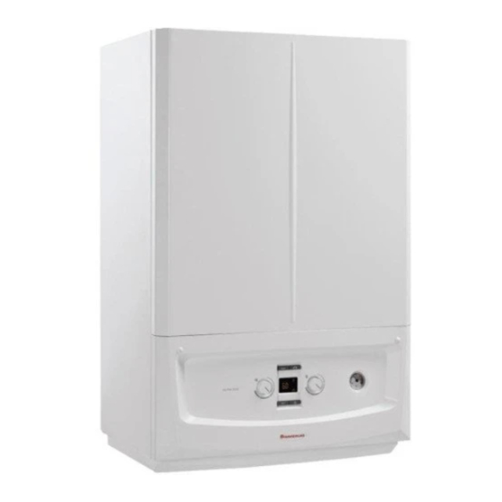
- Page 1 VICTRIX ZEUS 25 Condensing wall hung boiler with built-in storage tank ➢ VICTRIX ZEUS 25 20 kW for CH; 25 kW for DHW ➢ VICTRIX ZEUS 32 28 kW for CH; 32 kW for DHW Customer Service...
- Page 2 VICTRIX ZEUS ➢ Main features ➢ Hydraulic circuit ➢ Gas and flue circuit ➢ Control panel ➢ Electronic board and parameters setting ➢ Calibration ➢ Main options Customer Service...
- Page 3 Main features ➢ Stainless steel primary heat exchanger with aluminum shell ➢ 45 liters stainless steel storage tank ➢ Advanced electronics - Capable to fit any gases changing PCB parameters ➢ Electronic gas valve ➢ Modulation range from 14÷100% ➢ Low consumption modulating pump ➢...
- Page 4 Energy label Customer Service...
- Page 5 Dimensions and connections Height Width Depth (mm) (mm) (mm) Connections System 3/4" 1/2" 1/2" 3/4" 3/4" Key: - Voltage supply - Gas supply - Condensate drain (min. Ø13 mm) - System return - System delivery - DHW recirculation pump (optional) - DHW outlet - DHW inlet Customer Service...
- Page 6 Main components Key: 1 - Filling valve system 2 - Draining valve system 3 - Bypass 4 - 3-way valve (motorised) 5 - 3 bar safety valve 6 - Gas valve 7 - Boiler pump 8 - Air intake pipe 9 - Flow probe 10 - Return probe 11 - Air / gas manifold...
- Page 7 Electrical connections Removing the aesthetic frame and the cover, it is possible to access to the external electrical connection of the PCB. Electrical supply 230Vac 50Hz 21 State signal 40-41 Room thermostat 44-41 CAR 14-15 Safety thermostat Low temp. 38-39 External probe Customer Service...
- Page 8 VICTRIX ZEUS ➢ Main features ➢ Hydraulic circuit ➢ Gas and flue circuit ➢ Control panel ➢ Electronic board and parameters setting ➢ Calibration ➢ Main options Customer Service...
- Page 9 Hydraulic circuit Key: 1 - Gas valve 2 - Condensate drain trap 3 - 3 bar safety valve 4 - System draining cock 5 - System expansion vessel 6 - Air / gas mixer 7 - Fan 8 - Return probe 9 - Ignition/detection electrode 10 - Flue probe 11 - Flue hood...
- Page 10 Condensing module New primary heat exchanger with stainless steel single coil and aluminium shell ➢ No manifolds ➢ Internal section wide and constant ➢ High water flow ➢ Frontal access for servicing Customer Service...
- Page 11 Condensing module N° DESRIPTION MATERIAL Upper half-shell Alluminium FRONT flange Alluminium SPIRAL Steel Rear insulation Vermiculite Rear deflector Alluminium Hydraulic connections XYRON Lower half-shell Alluminium Customer Service...
- Page 12 Condensing module ➢ To protect the inside of the aluminum module casing from the condensate connection, the rear deflector and the lower half-shell are treated with a PTFE (Teflon) coating process: ➢ The rear deflector is covered throughout the surface facing outwards from the combustion chamber, so as to resist the attack of the condensate that may come from the flue gas discharge pipe;...
- Page 13 Condensing module • Increase in useful power by varying only the height of the coil tube, the external dimensions are the same for the different powers dimensional compactness; • The large and constant internal section allows you to limit deposits, with less risk of clogging in the presence of impurities in the water;...
- Page 14 Condensing module Same shelle dimensions for both echanger (25 kW and 32 kW), baut with different coil height. 25 kW The height of the tube reduces the space between the shell 32 kW and the coil Customer Service...
- Page 15 Condensing module The module have the same external dimension for both exchanger (25 kW e 32 kW) but different length of coil. 25 kW 32 kW Different colour: Black for 25 kW Grey for 32 kW Customer Service...
- Page 16 Hydraulic group Pump group in composite material designed in collaboration with Grundfos Automatic air vent valve 3-way valve motor Filling Low consumption modulating System by-pass 3 bar relief valve circulator 6mwc valve Customer Service...
- Page 17 Double NTC probe Functions related to ΔT between flow and return probe: 1. Proportional power limitation ΔT = 30°C → Proportional power limitation ON ΔT = 40°C → Maximum power limitation (boiler works at minimum power) Not enabled during “chimney sweep” mode 2.
- Page 18 Circulator graphic – ZEUS 25 Flow rate l/min. A+B = Available head to the system with closed by-pass = Available head to the system with opened by-pass C+D = Absorbed power with opened by-pass = Absorbed power with closed by-pass Customer Service...
- Page 19 Circulator graphic – ZEUS 32 Flow rate l/min. A+B = Available head to the system with closed by-pass = Available head to the system with opened by-pass C+D = Absorbed power with opened by-pass = Absorbed power with closed by-pass Customer Service...
- Page 20 Modulating pump In DHW mode the pump always runs at maximum speed. In heating mode, the pump speed can be set in 3 different ways by changing the parameters A3, A4 and A5: FIXED SPEED ➢ setting parameter A3 and A4 to the same value CONSTANT ΔT (Standard, parameter A5=15) ➢...
- Page 21 Storage tank Stainless steel 45 litres storage tank with magnesium anode and improved insulation Victrix Zeus 25 Victrix Zeus 32 Bigger coil to allow exchange the 32 kW The same flow limiter used on combi boiler Hydraulic fitting DHW Inlet,...
- Page 22 3-way valve motor The PCB drives the stepper motor following 3 phases: 1. Initial phase: Slow movement to increase torque for the shutter separation 2. Intermediate phase: Fast movement to decrease flow deviation time 3. Final phase: Twitch movement to avoid water hammer With boiler in Stand-by mode, the 3-way valve is positioned in the middle.
- Page 23 Condensate syphon Flue hood connection Condensing module connection Clean the syphon during O-ring the yearly maintenance Condensate discharge Customer Service...
- Page 24 VICTRIX ZEUS ➢ Main features ➢ Hydraulic circuit ➢ Gas and flue circuit ➢ Control panel ➢ Electronic board and parameters setting ➢ Calibration ➢ Main options Customer Service...
- Page 25 Combustion and gas circuit Flue hood Gas nozzle Condensing module gaskets Burner gasket Burner Insulation Air/gas Electronic gas valve mixer Customer Service...
- Page 26 SVG B&P Gas valve - SVG electronic gas valve doesn’t need any mechanical regulation. All the setting and regulations are made through the PCB Key: 1. Outlet pressure point 2. Modulation coil 3. Electrical connection 4. Inlet pressure point Customer Service...
- Page 27 Electronic combustion control Victrix Zeus is equipped with a new electronic system that allows to manage the combustion air and gas ratio. This system is able to control the instantaneous CO value, through the flame flame impedance signal detected by the electrode ( flame Through laboratory tests each values of CO have been matched to a certain...
- Page 28 Electronic combustion control The flame impedance value changes according to the quantity of gas involved in the combustion process. Increasing GAS quantity → decrease flame impedance Decreasing GAS quantity → increase flame impedance Ground Flame signal path Customer Service...
- Page 29 Electronic combustion control (3 starting points) In the PCB software are stored the pre-set impedance values to follow order to maintain the best combustion condition: one for each kind of boilers and for each kind of gas. With these 3 starting points, the PCB creates a working CO curve controlling the boiler modulation.
- Page 30 Electronic combustion control Victrix Zeus 25 - Maximum Power - NG Target flame signal 24 (kΩx10) to guarantee CO level 9,20 Ground Flame signal Increase GAS Decrease GAS Flame signal path Customer Service...
- Page 31 Advantages Electronic combustion control is able to instantaneously adapts the combustion value as the combustion components change (gas and air): - Gas with different composition (especially using LPG) - Different air density No need of manual adjustments on the gas valve No need to nozzle substitution This allows the boiler to constantly keep over time: ➢...
- Page 32 VICTRIX ZEUS ➢ Main features ➢ Hydraulic circuit ➢ Gas and flue circuit ➢ Control panel ➢ Electronic board and parameters setting ➢ Calibration ➢ Main options Customer Service...
- Page 33 Control panel DHW temperature Summer/Winter Reset button Display Pressure regulating knob button gauge CH temperature Information button Off, Stand-by, On button regulating knob Customer Service...
- Page 34 Display DHW request Stand-by Reset block External devices connected Burner on and relative heat output 10. Not enabled Summer mode 11. External probe connected (optional) Winter mode 12. CAR connected (optional) CH request 13. Not enabled Temperatures, error codes and information Customer Service...
- Page 35 Functioning mode Pressing button the boiler Summer/Winter switches from Stand-by mode selection mode to “Summer-Winter” mode Summer Winter Stand-by Pushing button for 8 seconds, the boiler switches off. Pushing again button the boiler switches on in the previous selected mode. Stand-by: Boiler supplied but not active, safeties and faults activated.
- Page 36 VICTRIX ZEUS ➢ Main features ➢ Hydraulic circuit ➢ Gas and flue circuit ➢ Control panel ➢ Electronic board and parameters setting ➢ Calibration ➢ Main options Customer Service...
- Page 37 Victix Zeus 25 - Electrical wiring Customer Service...
- Page 38 Victrix Zeus 32 - Electrical wiring Customer Service...
- Page 39 Electronic control board Indications ➢ Operations, temperatures and diagnostic display Safeties ➢ Pump (30 sec) and 3-way valve (10 sec) anti lock function ➢ Central heating and D.H.W. anti freeze function (-5°C) ➢ Low circulation / locked pump safety ➢ Central heating post-operating pump (10 sec) ➢...
- Page 40 Electronic control board An extractable flash memory is fitted on the electronic board, on which are memorized all the configuration parameters and combustion parameters. When a damaged PCB is replaced, the «old» memory must be used in order to maintain the previous setting.
- Page 41 Air vent function Every time the boiler is electrically supplied, the “Air vent function” is activated. The circulator (100 sec ON, 20 sec OFF) and the 3-way valve (120 sec CH., 120 sec DHW) are cyclically switched on and off. This function takes 8 minutes and it is shown on the display by a countdown (94 steps, 5 seconds each).
- Page 42 Information menu Pressing «info» button for 1 second, the display shows the Information menu. Use «Info» button to scroll the menu till the end. Id Parameter Description d 0.0 Not used d 0.1 Displays the combustion signal d 0.2 Displays the primary heat exchanger output instant heating flow temperature d 0.3 Displays the instant storage tank unit temperature d 0.4...
- Page 43 Error codes Code Anomaly Code Anomaly Block for exceeding the maximum accumulated No ignition block time, close gas valve opening Safety thermostat block (over-temperature) High ΔT between delivery and return probe Flue safety thermostat block Low temperature safety thermostat(optional) Contacts resistance block Burner power limitation Flow probe anomaly CAR Wireless communication failure...
- Page 44 Error codes New error codes related to the modulating pump Error Description Note code The circulator PCB detects an high electrical absorption due to the locked Locked pump pump. The boiler shows the error but it doesn’t switch-off. The circulator PCB detects a low electrical absorption due to the presence Presence of air in the circulator of air in the hydraulic block.
- Page 45 New error codes ERRORE 03 – Flue thermostat The flue gas probe detects at temperature > 113°C for more than 5 sec. the error appears. Press Reset. ERRORE 29 – Flue probe The flue probe is broken or damage. E47 – Burner power limitation If the flue probe detects a flue temperature >...
- Page 46 Parameter programming To enter in the programming phase: - put the D.H.W. knob in position “6” and the central heating knob in position “9”. - push the buttons “RESET” and “Summer/Winter” at the same time for 8 seconds When the function is activated, 5 menus are available (G, P, t, A, F). It is possible to scroll the menus pushing button “Summer/Winter”...
- Page 47 Parameter programming Select the parameter in the active menu by means of the DHW knob Modify the value rotating the CH knob Confirm the modification pressing “RESET” button for 1 second. The display shows “88” to confirm. Customer Service...
- Page 48 Menu P Parameter Description Range Default Par. Defines the maximum heat output percentage of the boiler during the DHW max 0 - 99 % D.H.W. phase compared to the maximum heat output available Defines the minimum heat output percentage of the boiler compared to Min output 0 - P2 the minimum heat output available...
- Page 49 Menù P Parameter Description Range Default Par. 0 = Off 1 = Chiller remote activation 2 =General alarm 3 = CH phase active 4 = External gas valve power supply Relay 3(optional) 0 - 9 5 = heat pump 6 = activation of storage tank pump 7 = Main zone control Do not use on this boiler model Do not use on this boiler model...
- Page 50 Menù t Parameter Description Range Default Par. Central heating set point Defines the minimum flow temperature. 20 ÷ 50 °C minimum temperature Central heating set point Defines the maximum flow temperature. (t0+5) ÷ 85 °C maximum temperature Defines the flow temperature during the storage tank central heating phase 0: Flow temperature = Set DHW + 25°C DHW thermostat...
- Page 51 Menù t Parameter Description Range Default Par. 0 - 840 Central heating ramp In the heating stage, the boiler performs an ignition ramp in order to seconds timer reach the maximum output set (step 10 sec) The boiler is set to switch-on immediately after a request. In the 0 - 600 CH ignition delay from event of particular systems (e.g.
- Page 52 Menu A Parameter Description Range Default Par. Hydraulic model It defines the hydraulic type of the boiler Not available Circulator model It defines the circulator type of the boiler 0 - 3 Modulating pump with PWM signal with return probe Maximum pump speed It defines the max circulator speed 1 ÷...
- Page 53 - LG To enter in submenu “n” and “S” press button “Reset”. Sub menu Description Range Default Boiler model 15=Victrix ZEUS 32 Boiler model 16=Victrix ZEUS 25 Submenu Parameter Description Range Default Minimum power 750 ÷ 1700 rpm 1150 Maximum power S0 ÷...
- Page 54 Menu F Id Par. Parameter Description Range Default Flue pipe lenght It defines the lenght of the flue pipes Not used “F0” allows to define the fan speeds in “S” menu (Min, Ignition, Max) according to the flue pipe length. With the “flue pipe test”...
- Page 55 At this point, it is possible to verify the ΔP connecting a micromanometer to the pressure points. Insert in the parameter F0 the correct value according to the ΔP measured, following this table: Victrix Zeus 25 Parameter F0 Pressure < 90 Pa 90 ÷...
- Page 56 VICTRIX ZEUS ➢ Main features ➢ Hydraulic circuit ➢ Gas and flue circuit ➢ Control panel ➢ Electronic board and parameters setting ➢ Calibration ➢ Main options Customer Service...
- Page 57 Calibration (relation between Impedance and To check the accuracy of the curve functioning , it is necessary to verify and to calibrate the system at 3 specific power output levels: ➢ Maximum power ➢ Intermediate power (ignition) ➢ Minimum power Flame set VICTRIX ZEUS (kΩx10)
- Page 58 Calibration The boiler leaves the factory calibrated according to the following working conditions: Parameter G = nG (natural gas) Parameter F0 = 0 According to the kind of installation, could be necessary to change some combustion parameters. In this case a new calibration is needed. There are 2 types of calibration: (display shows E62) Complete calibration...
- Page 59 Commissioning Needed technical equipment: Micro-manometer Instruction booklet Combustion analyser Start up mandatory conditions: - Closed sealed chamber - Filled syphon - Flue pipe properly installed - Gas pressure within the range Customer Service...
- Page 60 Commissioning Calibration Ignite the boiler (2-3 minutes, to be sure to have only gas and no air into the pipeline) Carry out the Flue pipe test (report the value in the instruction booklet) Display shows E72 Fast Parameter F0=0 calibration required Display shows E62 Parameter G=nG Complete calibration...
- Page 61 Calibration and Maintenance Substituted component Calibration required Gas valve Fast calibration Fast calibration Burner Complete calibration Ignition and detection electrode Complete calibration PCB (with new flash memory) Complete calibration PCB (using flash memory of the removed PCB) No calibration needed Condensing module Fast calibration Customer Service...
- Page 62 Complete calibration To activate the calibration boiler has not to be in Stand-by mode and without active requests (DHW or heating) Rotate DHW selector in position “6” and heating selector in position “9” Insert the combustion analyser in the specific hole and press RESET button for 8 seconds to enable “Chimney sweep”...
- Page 63 Complete calibration When “Chimney sweep” function is enabled (flashing ), press button within 3 seconds to enter in the Complete calibration (flashing … within 3 secs … Customer Service...
- Page 64 Nominal heat output calibration Once the function is enabled, the PCB supplies the gas valve to find out the ignition voltage of it. After that the PCB adjust the gas valve in order to reach the pre-set impedance value at maximum power (DHW). In this phase, the display shows alternatively the instantaneous temperature and the boiler power (99%) When PCB reach the pre-set impedance value, the frame around the flame symbol...
- Page 65 “Intermediate power”. at nominal at intermadiate at minimum Boiler output (99%) power (53%) power (0%) 9,20 ± 0,5 9,00 ± 0,5 9,00 ± 0,5 Victrix ZEUS 25 10,20 ± 0,5 10,00 ± 0,5 10,00 ± 0,5 Customer Service...
- Page 66 modification If the measured CO value is outside the limits, it is possible to correct it. When PCB reach the pre-set impedance value, the frame around the flame symbol on the display starts to flash. At this point, press “RESET” button to enter in the submenu for CO modification.
- Page 67 modification ➢ Press “INFO” button to decrease flame set (increase CO value); ➢ Press “Stand-by” button to increase flame set (decrease CO value); Increase CO Decrease CO Press “RESET” to confirm the new flame set value. Customer Service...
- Page 68 Intermediate power calibration After the nominal heat output calibration, pressing “INFO” button it is possible to proceed with the calibration at “Intermediate power”. In this phase, the display shows alternatively the instantaneous temperature and the intermediate boiler power (normally 44% but it depends from the boiler model) When PCB reach the pre-set impedance value, the frame around the flame symbol on the display starts to flash.
- Page 69 “Minimum power”. at nominal at intermadiate at minimum Boiler output (99%) power (53%) power (0%) 9,20 ± 0,5 9,00 ± 0,5 9,00 ± 0,5 Victrix ZEUS 25 10,20 ± 0,5 10,00 ± 0,5 10,00 ± 0,5 Customer Service...
- Page 70 Minimum power calibration After the intermediate calibration, pressing “INFO” button it is possible to proceed with the calibration at “Minimum power”. In this phase, the display shows alternatively the instantaneous temperature and the minimum boiler power (00%) When PCB reach the pre-set impedance value, the frame around the flame symbol on the display starts to flash.
- Page 71 Before leaving the calibration function, the boiler will work approximately another minute. at nominal at intermadiate at minimum Boiler output (99%) power (53%) power (0%) 9,20 ± 0,5 9,00 ± 0,5 9,00 ± 0,5 Victrix ZEUS 25 10,20 ± 0,5 10,00 ± 0,5 10,00 ± 0,5 Customer Service...
- Page 72 Fast calibration To activate the calibration boiler has not to be in Stand-by mode and without active requests (DHW or heating) Rotate DHW selector in position “6” and heating selector in position “9” Press RESET button for 8 seconds to enable “Chimney sweep”...
- Page 73 Fast calibration When “Chimney sweep” function is enabled (flashing ), press “INFO” button within 3 seconds to enter in the Fast calibration (flashing … within 3 secs … Customer Service...
- Page 74 Fast calibration Once the function is enabled, the PCB supplies the gas valve to find out the ignition voltage of it. After that the PCB adjust the gas valve in order to reach the pre-set impedance value at maximum power, intermediate power and minimum power. The calibration proceeds automatically without the possibility to regulate the flame set and consequently the CO values.
- Page 75 VICTRIX ZEUS ➢ Main features ➢ Hydraulic circuit ➢ Gas and flue circuit ➢ Control panel ➢ Electronic board and parameters setting ➢ Calibration ➢ Main options Customer Service...
- Page 76 Options CRONO 7 Digital room thermostat External probe DOMINUS interface board Configurable relay board Customer Service...
- Page 77 Options Cover kit Frost protection kit (-15°C) Safety thermostat kit for low temperature zone Magnetic filter Polyphosphates kit Customer Service...
- Page 78 Options Multi-zone Condensate discharge electronic board compact pump kit Recirculation kit with DHW pump Recirculation kit - only probe pipe Customer Service...
- Page 79 System manager It is possible to connect the boiler with the System manager in case of integrated system with heat pump. In order to make this configuration it is necessary to: ➢ Set the parameter “P7” must be set on value “CE” ➢...