
Related Manuals for Immergas VICTRIX 75


Summary of Contents for Immergas VICTRIX 75
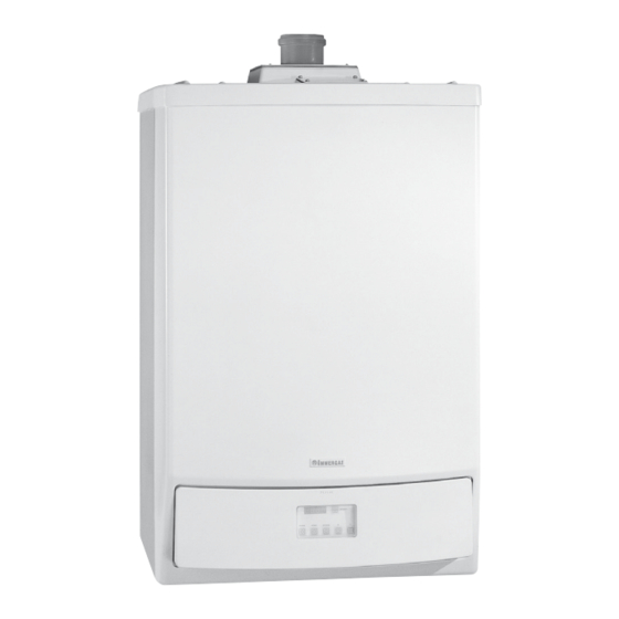
- Page 1 VICTRIX 75 Condensation-type wall-hung boiler for Central Heating only pre-engineered for external storage tank...
- Page 3 -5 °C. The VICTRIX 75 boiler must be installed using specific air/flue kits capacities of 80, 105, 120 and 200 litres. The boiler is approved for installation both inside a heating station...
- Page 4 Technical Documentation Technical Documentation VICTRIX 75 main dimensions. Legend: Height (mm) Width (mm) Depth (mm) V - Electrical connection G - Gas supply R - System return M - System flow Connections SC - Condensate discharge SYSTEM (minimum internal diameter 13 mm Ø)
- Page 5 Technical Documentation Technical Documentation VICTRIX 75 main components. Legend: 15 - System pressure switch 1 - Drain funnel 16 - Flow manifold 2 - Burner 17 - 4-bar safety valve 3 - Draught diverter 18 - P.C.B. 4 - Flue thermostat...
- Page 6 Technical Documentation Technical Documentation VICTRIX 75 Control Panel. Legend: 1 - Main switch 2 - User interface display 3 - Boiler manometer STV75 ed 01/08 VICTRIX 75...
- Page 7 Technical Documentation Technical Documentation VICTRIX 75 hydraulic circuit. 16 - Flue sample point Legend: 1 - External funnel drain 17 - Automatic air vent valve 2 - ISPESL certified 4 Bar safety valve 18 - System flow adjustment probe 19 - System return adjustment probe...
-
Page 8: Operation
D = Head available to the system at second speed with check valve for boilers in cascade (battery) Pump. The pump works on the primary circuit return and it is physi- cally coupled to the components supporting plate. STV75 ed 01/08 VICTRIX 75... -
Page 9: Primary Heat Exchanger
It is located at the front of the flow manifold body to which it is coupled. When this valve trips it causes water to come through the system flow pipe to which an extension pipe (4) is connected that ends with a collection funnel (5). System flow STV75 ed 01/08 VICTRIX 75... -
Page 10: Gas Valve
Through nozzle (6), gas is injected at the inlet of the Venturi pipe (5) where pre-mixing begins with the combustion air. The resulting mix is ignited on the cylindrical burner surface (4) by a spark of the ignition electrodes (10). STV75 ed 01/08 VICTRIX 75... - Page 11 At the end of the Venturi pipe is a pressure pick-up point where the input signal (P1) is read. This signal is conveyed to the pneumatic valve regulating the gas pressure via a silicone pipe. STV75 ed 01/08 VICTRIX 75...
- Page 12 Note: in case of ignition block it’s required to check the dis- tances of the ignition electrodes and of the detection electrodes sticking to the values shown in the figure at this side. Check moreover that there are no insulating cinders on the detection electrodes. STV75 ed 01/08 VICTRIX 75...
- Page 13 Undo the two screws (7) and (6) fastening the module to the two triangular mounting cross-pieces (rails), mounted onto the back of the boiler. Loosen the screw (2) located under the STV75 ed 01/08 VICTRIX 75...
- Page 14 - if the values are incorrect, bring them back to the limits G 31 10.50 % ± 0.2 9.70 % ± 0.2 with the gas valve flow adjustment screw (12). Turn clockwise to reduce the CO , turn counterclockwise to increase it. STV75 ed 01/08 VICTRIX 75...
-
Page 15: Gas Conversion
“No. 26” (see nominal and minimum heat output adjustment). Finally, check the carbon dioxide (CO2) value at maximum and minimum output and if necessary adjust by means of the off-set signal (see air-gas ratio adjustment). STV75 ed 01/08 VICTRIX 75... - Page 16 The flue hood and flue exhaust duct are protected by a thermostat plastic cover) and from where combustion air (8) and flue (9) (12) that is triggered when the temperature exceeds 90 °C. can be sampled. STV75 ed 01/08 VICTRIX 75...
-
Page 17: Air Inlet
(125 Ø) of the concentric adapter (2) slotted into the For a correct installation of the VICTRIX 75 boiler it is neces- draught diverter (1) which is connected to the fan with a sary to use the specific set of air inlet and exhaust pipes that plastic pipe. - Page 18 No.1 - Concentric curve 80/125 Ø at 87° (4) No.1 - Moveable half shell (8) No.1 - Concentric air inlet/exhaust end piece 80/125 Ø (5) No.1 - Internal washer (6) No.1 - External washer (7) STV75 ed 01/08 VICTRIX 75...
- Page 19 Technical Documentation Technical Documentation Fan-assisted open chamber configuration. (type The VICTRIX 75 boilers leave the factory in the B con- 80 Ø vertical exhaust kit. figuration. Connection to the boiler is done using the vertical 80 Ø ex- haust end piece (2) in PPS.
- Page 20 With this kit it is possible to duct 80 Ø pipes of existing turned in any direction and which, using the necessary extensions, flues/stacks/technical slots to be used with one Immergas is connected to the relative exhaust end piece (2) made of PPS.
-
Page 21: Electrical Circuit
- Line fuse (terminal block) - Gas valve (24 Vdc) - Transformer fuse The VICTRIX 75 electrical circuit is connected to a microproc- Some of the device on the circuit work at mains voltage (230 Vac) while others work at a low voltage. -
Page 22: Low Voltage Circuit
When open (N.O. contact) it enables operation in the central heating Summer switch (S16) mode. It enables operation in the domestic hot water mode when the Two-contact switch. contacts are closed. (not provided to Immergas) STV75 ed 01/08 VICTRIX 75... - Page 23 It is powered by the electronic integrated board (24 V). (optional) It is powered (24 V) by the electronic integrated board when burner ignition is necessary. Gas valve (Y1) (main coils) It allows passage of gas to the burner. STV75 ed 01/08 VICTRIX 75...
- Page 24 (E1) and then both gas valve coils (Y1). Burner ignition is detected by the board by way of the ioniza- tion electrode (E2). STV75 ed 01/08 VICTRIX 75...
- Page 25 No. 4 “Central heating flow tempera- ture”, the board enables the start of the ignition cycle. During ignition, the fan works at a speed that is given by the value set with parameter No. 28 - between maximum and minimum. STV75 ed 01/08 VICTRIX 75...
- Page 26 10°C. During operation, the water in the primary circuit remains below 10°C because when this temperature is reached the board switches the burner off. STV75 ed 01/08 VICTRIX 75...
- Page 27 When closed it enables operation in the domestic hot water mode, disabling Heating ON (S16) operation in the central heating mode. Closed = Central (not provided to Immergas) Heating OFF It powers the integrated board and allows operation of the boiler in the Open = Power OFF Main switch central heating or d.h.w.
- Page 28 With it, it is possible to vary the air flow to the Venturi pipe and hence the pressure of the gas to the burner. It is a signal that, according to the keys selected, displays the operating values and the boiler error Display codes. STV75 ed 01/08 VICTRIX 75...
-
Page 29: Safety Devices
Breakage of the flow probe (B1) prevents boiler operation. NTC flow probe breakage Triggering is indicated by error code “E31” or “E36” displayed on the boiler panel monitor. (B1) A manual reset, performed by pressing the relative button, is required to restore operation. STV75 ed 01/08 VICTRIX 75... - Page 30 If there is no fan signal the burner is switched off. Triggering is indicated by error code “E28” or “E29” on the display of the boiler panel monitor. Fan safety device A manual reset, performed by pressing the relative button, is required to restore operation. STV75 ed 01/08 VICTRIX 75...
- Page 31 Technical Documentation Technical Documentation VICTRIX 75 modes and operating status. The boiler is equipped with a self-adjustment board that can be 9 / b xx Burner off for one of the following reasons: accessed after the cover has been opened; it consists of a 4-digit - system flow temperature (T1) higher than 92°C...
- Page 32 Not active (external tempera- -37 (value in °C) ture, if the probe is installed) Flow temperature set-point Value in °C 7, 8, 9 Temperature gradients (cannot °C / s be altered) Flame current value µA STV75 ed 01/08 VICTRIX 75...
- Page 33 Technical Documentation Technical Documentation Programming and setting the VICTRIX 75 parameters. The boiler leaves the factory with the operating parameters Access code: already set. To alter the parameters reserved to the technician the access To adapt the boiler to your particular needs these operating code “54”...
- Page 34 0 = phase with burner on DHW - heating mode transition timer 30 = phase with burner off for 10 s Max. time with DHW prioritised 0 min. 120 min. 0 min. Cascade address NOT ENABLED STV75 ed 01/08 VICTRIX 75...
- Page 35 Min. rpm for pressure switch (x 100) Min. temperature for boiler maintain func- 0 °C 80 °C 0 °C tion Ramp up for heating or heating+DHW 0 (heating only) 1 (heat+DHW) function Pre-ignition time NOT ENABLED STV75 ed 01/08 VICTRIX 75...
- Page 36 Change the electronic board Check the flow probe / electronicboard Block in the flow probe control circuit Change the electronic board Check the circulation of water in the System flow temperature is too high (over 95 °C) system STV75 ed 01/08 VICTRIX 75...
- Page 37 Waiting for the fan to start (insufficient air flow) Check fan function Loss of ionising current during burner ignition (after 3 attempts, Check gas and electricity supplies b 118 fault becomes error "02" ignition inhibition) Check gas supply pressure STV75 ed 01/08 VICTRIX 75...
-
Page 38: Heating Phase
Technical Documentation Technical Documentation VICTRIX 75 operating sequence. Heating phase. Power on Main switch ON Integrated board operation enabled Closing of the main switch contacts (ON position) enables operation in the central heating mode Powering the fan The integrated board powers the fan ... -
Page 39: Technical Specifications
Technical Documentation Technical Documentation Technical specifications. Technical specifications, VICTRIX 75. Nominal heat input kW (kcal/h) 74.6 (64169) Minimum heat input kW (kcal/h) 18.5 (15949) Nominal (useful) heat output kW (kcal/h) 72.6 (62436) Minimum (useful) heat output kW (kcal/h) 18.1 (15566) Effective efficiency 80/60 Nom./Min. - Page 40 30 / 16 389 / 78 31 / 15 Flue temperature at nominal heat output °C Flue temperature at minimum heat output °C VICTRIX 75 variable heat output. NATURAL GAS (G20) BUTANE (G30) PROPANE (G31) HEAT HEAT BURNER GAS FAN SPEED...
- Page 41 Technical Documentation Installation of a single VICTRIX 75 boiler. The VICTRIX 75 boiler can be installed singly and work in the central heating mode only, to which an external storage tank can be coupled if wanted, by way of a specific 3-way diverter valve...
- Page 42 Kit 3-way diverter valve for coupling the exter- G1"1/2 nal storage tank (optional). G1"1/2 With this kit the VICTRIX 75 boiler can be connected - if G1" wanted - to an external storage tank for the production of domestic hot water.
- Page 43 Technical Documentation Technical Documentation Example of a single VICTRIX 75 installation. The above example refers to a boiler equipped with an ISPESL The system is controlled by a zones and cascade regulator (2) safety kit and a distribution manifold. The system consists of...
-
Page 44: General Features
VICTRIX 75 which is designed also for installation in cascade case, for example, of maintenance on one of the connected boilers;... - Page 45 Flue manifold for boilers in a cascade (optional). The VICTRIX 75 boilers installed in a cascade (battery) in the The slanting angle of the 125 Ø discharge manifold must be at configuration, can be connected, by means of a manifold, least 3°...
- Page 46 Technical Documentation Technical Documentation Example of installing VICTRIX 75 in a cascade. The above example refers to three boilers installed in a cascade, The system is controlled by a cascade regulator (2) that controls equipped with an ISPESL safety kit and a mixing manifold the storage tank directly, two zone managers (3) that control the (26).
-
Page 47: List Of Optional Accessories
Flue exhaust manifold kit with flue adjusting device water tank when an additional boiler is added to the cascade code 3.015241 (it includes water tank probe) (it is not to be installed along with a cascade regulator) code 3.015223 STV75 ed 01/08 VICTRIX 75...