Advertisement
Quick Links
Advertisement

Related Manuals for Immergas EOLO Extra 24 kW


Summary of Contents for Immergas EOLO Extra 24 kW
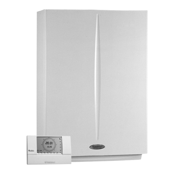
- Page 1 EOLO Extra kW Instant wall-hung boilers airtight chamber for outdoors...
- Page 3 Technical Documentation Technical Documentation EOLO Extra kW Wall-hung room sealed fan assisted boiler for outdoors. EOLO Extra 24 kW EOLO Extra 28 kW EOLO Extra 32 kW General features. EOLO Extra kW is a wall-hung room-sealed fan-assisted The supply of combustion air to inside the sealed chamber and...
- Page 4 Technical Documentation Technical Documentation EOLO Extra 24 kW main dimensions and connections. Height (mm) Width (mm) Depth (mm) CONNECTIONS DOMESTIC SYSTEM WATER 1/2” 1/2” 1/2” 3/4” 3/4” Legend: G - Gas supply AC - D.h.w. outlet AF - D.h.w. (cold) inlet...
- Page 5 Technical Documentation Technical Documentation EOLO Extra kW Control panel. Legend: 1 - Stand by LED 12 - Stand-by / On / Programming / Reset main switch 2 - Burner on LED 13 - Parameters selection knob 3 - D.h.w. on LED 14 - Parameters modification knob 4 - Central heating on LED 15 - Boiler manometer...
- Page 6 Technical Documentation Technical Documentation EOLO Extra 24 kW main components. Legend: 1 - Boiler pressure gauge 15 - Safety thermostat 2 - Domestic water probe 16 - Draught diverter 3 - D.h.w. flow switch 17 - Primary exchanger 4 - Gas valve...
- Page 7 Technical Documentation Technical Documentation EOLO Extra 28-32 kW main components. Legenda: 1 - Domestic water draining fitting 15 - Safety thermostat 2 - Domestic water probe 16 - Draught diverter 3 - D.h.w. flow switch 17 - Primary exchanger 4 - Gas valve 18 - Ignition and detection electrodes 5 - System pressure switch 19 - System expansion vessel...
- Page 8 Technical Documentation Technical Documentation EOLO Extra kW hydraulic diagram. Legend: 14 - System expansion vessel 1 - D.h.w. flow switch 15 - Automatic air vent 2 - Flow limiter 16 - Boiler circulator 3 - System filling valve 17 - System pressure switch 4 - Domestic water probe 18 - D.h.w.
- Page 9 (18). This depends on the position of the motorised 3-way valve EOLO Extra 24 kW Flow-rate l/h EOLO Extra 28 kW Flow-rate l/h A = Head available to the system on maximum speed with the by-pass off.
- Page 10 Technical Documentation Technical Documentation EOLO Extra 32 kW Flow-rate l/h A = Head available to the system on maximum speed with the by-pass off. B = Head available to the system on maximum speed with the by-pass on. C = Head available to the system at second speed with the by-pass off. D = Head available to the system at second speed with the by-pass on.
- Page 11 Technical Documentation Technical Documentation Motorised 3-way valve. It is an electric motor (1) connected to the 3-way unit (2) and locked by a fork that allows, according to the request made Exchanger (d.h.w. or central heating), boiler water to flow into the central Exchanger return delivery...
- Page 12 Technical Documentation Technical Documentation Safety devices and controls. Automatic system by-pass (4). This device guarantees circulation of water in the primary cir- cuit (between delivery and return) even when this is prevented by the system’s high resistance. It is installed between the circulator body and the 3-way unit.
- Page 13 Technical Documentation Technical Documentation Secondary circuit (D.h.w. Circuit). Operation. When domestic hot water is drawn cold water flows inside the d.h.w. flow switch (1) which closes the electrical contact coupled to it (see the electrical circuit). As a result, the integrated board starts the d.h.w. priority phase that ignites the burner and, if there’s an ongoing central heating request, switches the 3-way diverter valve (2) moving it into the working position (see operation of the hydraulic 3-way valve).
- Page 14 Technical Documentation Technical Documentation D.h.w. flow switch (2). Whenever domestic hot water is drawn at a rate of at least 1.5 l/min and a dynamic pressure of 0.3 bar, the flow switch (2) enables the boiler to work in the d.h.w. mode. This is done by means of a magnet that, lifting when hit by the flow of domestic cold water, moves near to an electrical contact (reed relay) causing it to move thanks to the magnetic effect.
- Page 15 Technical Documentation Technical Documentation Gas circuit. This circuit consists of an atmospheric burner and a modulat- Burner. ing gas valve that permit, respectively, the combustion of gas The burner consists of horizontal Venturi pipes (6) inside which and the regulation of its flow rate. gas is injected by the same number of nozzles (7) mounted on the respective manifold (8).
- Page 16 Technical Documentation Technical Documentation Gas adjustments. The maximum and the minimum gas pressure adjustments SIT 845 gas valve can be made on the gas valve respecting the values shown in Adjustment maximum pressure. the heat outputs table, in function of the model and the gas Run off...
- Page 17 Technical Documentation Technical Documentation Flue circuit. Operation. The products of combustion, after having hit the water-gas Flue pressure switch (6). exchanger (2), are slowed down and distributed by the plate It is located at the top inside the sealed chamber and detects, by (12) thus increasing combustion efficiency.
- Page 18 When it triggers it causes a switch to close (S6) that acts on the integrated board enabling or preventing burner ignition. Flue pressure switch triggering pressures Pa (mm H Pa (mm H EOLO Extra 24 kW 52 (5.3) 42 (4.3) EOLO Extra 28 kW 44 (4.5) 36 (3.7) EOLO Extra 32 kW 52 (5.3)
- Page 19 Technical Documentation Technical Documentation Intake and outlet systems. (see the intake and outlet terminal instructions). The EOLO Extra kW boiler is designed for connecting the couple-on air intake/outlet pipes and can be installed indoors or outdoors in the open or in a partly sheltered location in the following configurations: Outdoors (in the open): - room-sealed fan-assisted with direct air intake (type C)
- Page 20 Technical Documentation Technical Documentation Electrical circuit. ������������� ���� ����� ������� ����� ����� ����� E2 - Detection electrode ������������ E4 - Safety thermostat F1 - Line fuse F2 - Neutral fuse M1 - Boiler circulator M20 - Fan M30 - 3-way valve �������...
- Page 21 Technical Documentation Technical Documentation Loads. It is controlled by the integrated board that produces an electric discharge between the Ignition electrodes electrodes. (E1) Upon contact the air-gas mixture ignites. It is powered by the integrated board with a central heating or antifreeze request or with Boiler circulator a d.h.w.
- Page 22 Technical Documentation Technical Documentation It acts on the integrated board and enables boiler operation when Switching Flue pressure switch the flue are extracted correctly. If it is closed with the fan off it does not enable start of the igni- (S6) contact tion cycle.
- Page 23 Technical Documentation Technical Documentation Electrical circuit. Central heating phase. ��� ������� ���� ������� ����������� ������ �� �� ����������� ������� ����������������������������� ����������������� Operating with the Remote Control. The Remote Control (CAR) is enabled when the main selector ignition cycle starts, first controlling the ignition electrodes switch (R10) is in the “ON”...
- Page 24 Technical Documentation Technical Documentation Electrical circuit. Domestic hot water phase. ��� ������� ���� ������� ����������� ������ �� �� ����������� ������� ����������������������������� ����������������� Operation. The Remote Control (CAR) is enabled when the main selector switch (R10) is in the “ON” position. By running off...
- Page 25 Technical Documentation Technical Documentation Integrated board. NAT-LPG FUSES D.H.W. CENTRAL MAIN SELECTOR SWITCH HEATING TRANSFORMER of the 3-way valve which keeps working until limit switch “3” Inside the boiler’s panel is a microprocessor controlled p.c.b. opens when the central heating position is reached. that controls the appliance’s electrical devices, sees to the linear In the meantime, if the flue pressure switch (S6) contact is modulation of burner output and, by means of LEDs, shows...
- Page 26 Technical Documentation Technical Documentation Domestic hot water request. “Chimneysweep” request. When the d.h.w. flow switch (S4) closes, burner ignition pro- By turning the main switch (R10) round to Reset for 8 to 15 ceeds in the same way as for the central heating phase. seconds, upon its release the board enables boiler ignition and During the first few seconds from when the gas valve (Y1) was keeps it working at the maximum central heating power set...
- Page 27 Technical Documentation Technical Documentation Inputs. Zone control unit (CZ) It sends signals to the board concerning operating requests of zone valves or connected (external optional) external pumps (see zone control unit operation). Remote control It sends signals to the board of the SUMMER/WINTER selector switch concerning d.h.w. (CAR) and central heating temperature adjustment and the central heating request (times, room temperature, error codes, etc…).
- Page 28 Technical Documentation Technical Documentation Outputs. 230 Vac = coils Gas valve power supply It is a 230 V ac signal indicating that the main gas valve coils are energised (Y1) energised (Y1). 0 Vac = coils not energised It is a high voltage signal (higher than 16 kV) that determines an electrical discharge at the Ignition electrodes (E1) ends of the ignition electrodes located on the burner.
- Page 29 Technical Documentation Technical Documentation Safety devices. The circulator (M1) and 3-way valve (M30) work for 30 seconds subsequent to: Circulator antiblock function / - 24 hours of being idle with the CAR SUMMER/WINTER selector on SUMMER. 3-way valve - 3 hours of being idle with the CAR SUMMER/WINTER selector on WINTER. In the event of high resistance of the system pressure switch, safety thermostat or flue pressure switch contact (not completely closed or worn), the integrated board effects a reset Electromechanical contacts...
- Page 30 Technical Documentation Technical Documentation To prevent the water-gas exchanger from overheating, at the end of each central heating, an- Post-circulation circulator tifreeze or “chimneysweep” request the circulator (M1) keeps working for 150 seconds. Sealed chamber After the burner switches off at the end of a request the combustion chamber is washed post-ventilation and the fan works for 30 seconds.
- Page 31 Technical Documentation Technical Documentation Indications and malfunctions. The EOLO Extra kW boiler signals malfunctions with the flashing of one of the LEDs, from 5 to 11, coupled to the (alternate) flashing of LED 1. CHANGE PARAMETERS SELESCT PARAMETERS Operating indications Remote display Boiler powered but no flame LED 1 on...
- Page 32 Technical Documentation Technical Documentation Programming the integrated board. The EOLO Extra kW boiler is designed for programming some For the association of the LED to the value, see the following operating parameters if wanted. tables: By modifying these parameters the boiler can be adapted to meet one’s specific requirements.
- Page 33 Technical Documentation Technical Documentation Permanent timing reduction. The boiler is fitted with an Central heating ignitions delayed due to Room thermostat electronic timer that prevents the burner igniting too frequently or Remote control requests. The boiler is set to turn on im- in the central heating phase.
- Page 34 Technical Documentation Technical Documentation Gas G110 – China Gas. The setting of this function serves to adjust the boiler to work with the gases of the first family. LED flashing China Gas Gas G110 - (first family gas) (slow) Off (Standard setting) LED 2 LED 11 Relay 1 operation*.
- Page 35 Technical Documentation Technical Documentation EOLO Extra kW operating sequence. Heating Phase D.h.w. Phase Switching on Switching on Turn the main boiler selector switch “ON” Turn the main boiler selector switch “ON” Ú Ú Enabling the integrated board and CAR (Remote Control) Enabling the integrated board and CAR (Remote Control) When the contacts of the main selector switch close the When the contacts of the main selector switch close the...
- Page 36 Technical Documentation Technical Documentation Technical data. EOLO Extra 24 kW technical data. Nominal heat input kW (kcal/h) 25,9 (22241) Minimum heat input kW (kcal/h) 10,7 (9195) Nominal heat output (useful) kW (kcal/h) 24,0 (20640) Minimum heat output (useful) kW (kcal/h) 9,3 (8000) Efficiency at 100%...
- Page 37 Technical Documentation Technical Documentation EOLO Extra 28 kW technical data. Nominal heat input kW (kcal/h) 30,1 (25892) Minimum heat input kW (kcal/h) 12,0 (10345) Nominal heat output (useful) kW (kcal/h) 28,0 (24080) Minimum heat output (useful) kW (kcal/h) 10,5 (9000) Efficiency at 100% 93,0 Efficiency at 30% of load...
- Page 38 Technical Documentation Technical Documentation EOLO Extra 32 kW technical data. Nominal heat input kW (kcal/h) 34,3 (29528) Minimum heat input kW (kcal/h) 12,2 (10500) Nominal heat output (useful) kW (kcal/h) 32,0 (27520) Minimum heat output (useful) kW (kcal/h) 10,5 (9030) Efficiency at 100% 93,2 Efficiency at 30% of load...
- Page 39 Technical Documentation Technical Documentation EOLO Extra 24 kW variable heat output. METHANE (G20) BUTANE (G30) PROPANE (G31) INJECTOR INJECTOR INJECTOR HEAT HEAT FLOWRATE PRESSURE FLOWRATE PRESSURE FLOWRATE PRESSURE OUTPUT OUTPUT BURNER BURNER BURNER BURNER BURNER BURNER (kW) (kcal/h) (mbar) (mm H...
- Page 40 Technical Documentation Technical Documentation EOLO Extra 32 kW variable heat output. METHANE (G20) BUTANE (G30) PROPANE (G31) INJECTOR INJECTOR INJECTOR HEAT HEAT FLOWRATE PRESSURE FLOWRATE PRESSURE FLOWRATE PRESSURE OUTPUT OUTPUT BURNER BURNER BURNER BURNER BURNER BURNER (kW) (kcal/h) (mbar) (mm c.a.) (kg/h) (mbar) (mm c.a.)