
Related Manuals for Comtrend Corporation GCA-6000


Summary of Contents for Comtrend Corporation GCA-6000
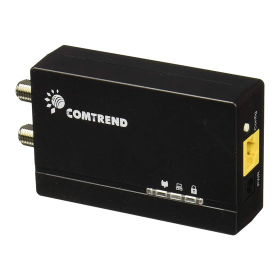
- Page 1 GCA- 6000 G.hn Coax Et hernet Adapt er User Manual Version A2.1, July 6, 2016 261072-037...
- Page 2 Preface This m anual provides inform at ion relat ed t o t he inst allat ion and operat ion of t his device. The individual reading t his m anual is presum ed t o have a basic underst anding of t elecom m unicat ions t erm inology and concept s.
- Page 3 Protect Our Environment This sym bol indicat es t hat when t he equipm ent has reached t he end of it s useful life, it m ust be t aken t o a recycling cent re and processed separat e from dom est ic wast e. The cardboard box, the plastic contained in the packaging, and the parts that make up this Coax ADAPTER can be recycled in accordance with regionally established regulations.
-
Page 4: Table Of Contents
Table of Contents Chapter 1 Quick Installation ........................... 5 Chapter 2 Introduction ............................9 2.1 Front Panel and LED indicators ........................9 2.2 Bottom Panel .............................. 10 2.3 How to understand the COVERAGE LED colors ..................11 2.4 Point-to-Point Network ..........................12 2.5 Point-to-Multipoint Network ........................ - Page 5 13.3 Factory Reset ............................33...
-
Page 6: Chapter 1 Quick Installation
Chapter 1 Quick Installation Understanding Your G.hn Coax Adapter NOTE: The following st eps show how t o creat e or add ont o a G.hn Coax Net work ( A m inim um of t w o G.hn Coax Adapt ers ar e required t o creat e a proper connect ion.) ... - Page 7 2. Connect the coaxial cable to the “IN” of the Coax Adapt er and t o a cable wall out let . 3. Ensur e t hat your net w ork device is pow ered on. Connect t he Coax Adapt er t o t he LAN port of t he network device with an Ethernet cable.
- Page 8 Note: The “TV” port on the Coax Adapter is meant for traditional Cable TV services. We do not recommend using t he Coax Adapt er if you receive Cable TV/ I nt ernet services. is off, press t he “Config” but t on on each We recom m end a secure net w ork.
- Page 9 ETHERNET LED is OFF: I f t he ETHERNET LED fails t o light up, check t hat t he LAN port of t he GCA- 6000 unit is connect ed firm ly t o t he LAN port of t he ot her device. To check t he condit ion of t he Et hernet cable, use anot her cable t o t est t he sam e connect ion.
-
Page 10: Chapter 2 Introduction
Chapter 2 Introduction Comtrend’s I TU-T G.hn net working st andard com pliant Et hernet adapt er provides t he best qualit y dat a t ransm ission at high- speed. The GCA- 6000 allows users t o ext end a local area net w ork via exist ing coax cables, elim inat ing t he need for ext ra Et hernet wiring. -
Page 11: Bottom Panel
Node is secur e ( it has eit her received or generat ed net w ork key s) Securit y Node is not secure, it has neit her received nor generat ed net w ork key param et ers ( dom ain Green nam e and encrypt ion key) Slow: Device is pairing... -
Page 12: How To Understand The Coverage Led Colors
2.3 How to understand the COVERAGE LED colors The COVERAGE LED display s qu alit y of t h e n et w or k an d pr ov ides im por t ant infor m at ion t hat w ill pr ov ide solut ion s t o com m on qu est ions, such as w hy a High Definit ion ( HD) m ov ie is not show ing or show s w it h pixels. -
Page 13: Point-To-Point Network
2.4 Point-to-Point Network CASE 1: Est im at ed t hroughput is less t han 20 Mbps. The Coax channel is not able t o t ransm it an SDTV channel. The COVERAGE LED will be RED as shown in t he following figure: ... -
Page 14: Point-To-Multipoint Network
2.5 Point-to-Multipoint Network I n t he case where t he Coax net work is com posed of t hree or m ore adapt ers, sim ilar sit uat ions could arise as wit h a point - t o- point net work. ... -
Page 15: Chapter 3 Log In Procedure
Chapter 3 Log In Procedure 3.1 Configure STATIC IP MODE I n st at ic I P m ode, you assign I P set t ings t o your PC m anually. Follow t hese st eps t o configure your PC I P address t o use subnet 192.168.0.x. NOTE: The following procedure assum es you ar e running Windows. -
Page 16: Logging In
3.2 Logging In Perform t he following st eps t o login t o t he web user int erface. STEP 1: St art t he I nt ernet brow ser and ent er t he default I P address for t he device in t he Web address field. For exam ple, if t he default I P address is 192.168.0.5, t ype ht t p: / / 192.168.0.5 STEP 2: A dialog box will appear, such as t he one below. -
Page 17: Chapter 4 G.hn Interface
Chapter 4 G.hn Interface... -
Page 18: Basic Configuration
4.1 Basic Configuration Domain Name a group nam e of all nodes in t he net w ork. Force node Type forces t he m odem t o have a part icular role ( END POI NT or DOMAI N MASTER) ... -
Page 19: Chapter 5 Ip Interface
Chapter 5 IP Interface... -
Page 20: Ip Config
5.1 IP config I n t he IP configuration t ab of one G.hn node, t he I Pv4 and I Pv6 set t ings can be read and changed. I Pv4 subsect ion: DCHPv4 enabled: t o enable t he I Pv4 DHCP configurat ion or choose not t o. I n t he case of choosing ”NO"... -
Page 21: Chapter 6 Ethernet Interface
Chapter 6 Ethernet Interface The Et hernet t able show s t he st at us & I nfo of t he Et hernet int erface; including I nt erface, Speed, Duplex, I nt erface Type, Mode, I nt ernal PHY & Link . Powersaving Et hernet powersaving can be disabled, enabled by Et hernet link or enabled by Et hernet act ivit y;... -
Page 22: Chapter 7 Device Interface
Chapter 7 Device Interface 7.1 HW information I n t his t ab, basic inform at ion such as Serial Num ber , MAC Address, HW Product and Revision is shown. 7.2 SW information Shows t he FW version and syst em upt im e. -
Page 23: Security
7.3 Security Configuration password The nodes in t he net work: t o change t he configurat ion password st ring from t he default ( " pat erna" ) t o anot her; decided by t he user. 7.4 SW Update Firmware update: This sect ion provides a m et hod t o upgrade t he flash m em ory in t he GCA- 6000 unit from a serv er using FTP or TFTP pr ot ocol. -
Page 24: Chapter 8 Multicast Interface
Chapter 8 Multicast Interface 8.1 MCAST Configuration I n t he MCAST Configuration t ab IGMP snooping and MLD feat ures can be enabled or disabled. Also, I GMP m ult icast I P addresses ranges which t he G.hn PLC net work will sniff; can be configured. ... -
Page 25: Chapter 9 Qos Interface
Chapter 9 QoS Interface... -
Page 26: Qos Configuration
9.1 QoS Configuration I n t he QoS configurat ion t ab, t he packet classifier can be m anaged t o define a QoS rule for incom ing Et hernet t raffic, and assign a priorit y t o be used in t he G.hn net work. Press t he “OK" but t on for loading t he newly configured set t ings: Example 1... - Page 27 QoS CRITERION: a general crit erion can be chosen am ong " None" ( no QoS) , " Cust om " and " 802.1p" . Type of Frame: wit h t his param et er t he t ype of Et hernet t raffic being t ransm it t ed by t he G.hn net work should be select ed.
- Page 28 Example 2 I f QoS crit erion: 802.1p, all ot her opt ions ar e grayed out , and follow t he QoS rules below. According t o G.9960 specs, t he priorit y m apping recom m ended by [ I EEE 802.1D] subclause 7.7.3 is present ed in t he t able below for eight priorit y queues.
- Page 29 Priority Acronym Traffic Types 0 ( Third) Backgr ound 1 ( lowest ) Best Effort 2 ( lowest ) Excellent Effort 3 ( Third) Crit ical Applicat ions 4 ( second) Video, < 100 m s lat ency and j it t er 5 ( second) Voice, <...
-
Page 30: Chapter 10 Vlan Interface
Chapter 10 VLAN Interface 10.1 VLAN Configuration I n t he VLAN Configuration t ab of one G.hn node, a VLAN t ag can be added or rem ov ed per int erface. Also, rem oving a t ag at egress per int erface can be also enabled or disabled: ... -
Page 31: Chapter 11 G.hn Spectrum Interface
Chapter 11 G.hn spectrum Interface 11.1 Notches I n t his t ab a t able wit h all configured Notches of select ed node will be shown. I t is com posed of opt ions for ev ery not ch: Not ch I ndex, St art Frequency ( KHz) , St op Frequency ( KHz) , Dept h ( in dB) . The first 2 not ches ( Regulat ion) are Read Only, RO, in t he syst em and t hey can be neit her rem oved nor m odified. - Page 32 To add new not ches t he user should fill t he " Add a new User Notch" fields, set t ing St art and St op frequencies in KHz and dept h in dB of not ch and t hen press t he " OK" but t on. They will be added in first User free posit ion from num ber 0 t o 9 aft er t he screen refreshes.
-
Page 33: Chapter 12 Log File Interface
Chapter 12 Log file Interface 12.1 Log File I n t he Log File configurat ion t ab t he following set t ings can be read, and changed by clicking on t he " OK" but t on. Enable Log File set t o YES for enabling Log File funct ionalit y in t he node and set t o NO for disabling it . -
Page 34: Chapter 13 Advanced Interface
Chapter 13 Advanced Interface 13.1 Broadcast Suppression Broadcast t raffic higher t han t he input t ed value will be dropped. I nput t he required value ( Mbps) and click t he OK but t on. To deact ivat e t his funct ionalit y , set t he value t o 0. 13.2 Hardware Reset Click on t he Hardware Reset but t on t o perform a reboot ( hardw ar e reset ) .