
Related Manuals for Immergas VICTRIX 20 Plus


Summary of Contents for Immergas VICTRIX 20 Plus
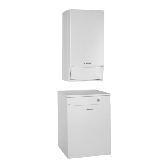
- Page 1 VICTRIX Plus Condensation-type wall-hung room sealed fan-assisted boiler for central heating only or with an external storage tank.
- Page 3 VICTRIX PLUS Condensation-type wall-hung room sealed fan-assisted boiler for central heating only or with an external storage tank. VICTRIX 20 Plus VICTRIX 27 Plus General features. VICTRIX Plus is a condensation type wall-hung room sealed The VICTRIX Plus boiler has to be installed using the suc- fan-assisted boiler for central heating only, designed to work tion/exhaust kit or the ducting systems (60 mm Ø...
- Page 4 Technical Documentation Technical Documentation VICTRIX 20 Plus main dimensions. 80-litre storage tank 105-litre storage tank 120-litre storage tank Legend: V - Power connection U - D.h.w. outlet 200-litre storage tank G - Gas supply RB - Boiler return MB - Boiler delivery A - System filling...
- Page 5 Technical Documentation Technical Documentation VICTRIX 27 Plus main dimensions. 80-litre storage tank 105-litre storage tank 120-litre storage tank Legend: V - Power connection 200-litre storage tank U - D.h.w. outlet G - Gas supply RB - Boiler return MB - Boiler delivery A - System filling E - D.h.w.
- Page 6 Technical Documentation Technical Documentation VICTRIX Plus main components. (from the serial number 3035590 for VICTRIX 20 Plus) (from the serial number 2773117 for VICTRIX 27 Plus) Legend: 1 - System filling valve 17 - Sleeve with Venturi housing 2 - Gas valve 18 - Electronic control unit 3 - System drainage fitting...
- Page 7 Technical Documentation Technical Documentation Storage tank main components. 105-litre storage tank 80-litre storage tank 120-litre storage tank Legend: 1 - Thermometer 2 - D.h.w. probe 3 - D.h.w. drainage cock 4 - D.h.w. expansion vessel 5 - Coil 6 - Magnesium anode 7 - Double coil 8 - Coil for use with solar panels 200-litre storage tank...
- Page 8 Technical Documentation Technical Documentation VICTRIX Plus control panel. Boiler control panel Storage tank control panel Legend: 1 - Central heating ON light 2 - Central heating temperature selector switch 3 - D.h.w. temperature selector switch 4 - D.h.w. ON light 5 - D.h.w./Remote Control –...
- Page 9 Technical Documentation Technical Documentation VICTRIX Plus hydraulic circuit. (from the serial number 3035590 for VICTRIX 20 Plus) (from the serial number 2773117 for VICTRIX 27 Plus) ������ ������������������������������ Legend: 1 - Gear motor for 3-way diverter valve 24 - Expansion vessel...
-
Page 10: Operation
It is connected to the enbloc by means of a threaded connec- tion while the condensation module and the expansion vessel are connected by means of coupling pipes (2) and an O ring VICTRIX 20 Plus (3), locked by special forks (1). Flow litres/h Head available to the system on maximum speed with the by-pass off... - Page 11 When this valve trips it causes water to exit from the delivery pipe. One-way valve (4). (up to serial number 2279840 for VICTRIX 20 Plus) During the d.h.w. mode it prevents natural circulation starting in the central heating system. “Europa” type one-way valve (5).
-
Page 12: Storage Tank
Technical Documentation Technical Documentation Secondary circuit (domestic hot water circuit). The secondary circuit comes into use whenever it is necessary This keeps the water inside the storage tank at a constant to bring the temperature in the storage up to the temperature temperature and, when water is drawn, the instant produc- tion of hot water. - Page 13 Technical Documentation Technical Documentation ON-OFF thermostat kit (12) (optional). This kit adapts storage tank operation to systems with ON- OFF type temperature control. It consists of a thermostat whose bulb is put in place of the NTC sensor and electrically wired to the storage tank’s control panel terminal board.
- Page 14 (optional) must have load losses less than those indicated in the following graphs according to the boiler model and type of storage tank Available head for the storage tank with Victrix 20 Plus. MAX HEAT EXCHANGE MAX HEAT EXCHANGE 80-litre STORAGE TANK COIL...
- Page 15 Technical Documentation Technical Documentation Motorised 3-way diverter valve. PUMP RETURN CENTRAL HEATING SIGNAL D.H.W. SIGNAL SYSTEM RETURN COMMON COIL RETURN This electric 3-way diverter valve works on the primary circuit return and, depending on the request made (d.h.w. or central heating), it transfers boiler water to the central heating system or to the storage tank coil.
- Page 16 Technical Documentation Technical Documentation Air-gas circuit. Suction and exhaust systems. (see suction and exhaust terminal instructions). Operation (see VICTRIX). Conventional flue configuration (type B ) for indoor installation (see VICTRIX). Gas valve (see VICTRIX). Fan-assisted sealed chamber configuration (type Fan (see VICTRIX). C) (see VICTRIX).
-
Page 17: Electrical Circuit
Technical Documentation Technical Documentation Electrical circuit. (from the serial number 3035590 for VICTRIX 20 Plus) (from the serial number 2773117 for VICTRIX 27 Plus) ������� ������� ���� ����� ������������������������������ ����������������������������� �������������������������� ����� ������� ������ ����� ��������� ������ ������ ����������������� ����������... - Page 18 Clicson twin-con- (from the serial number 3035590 It is positioned on the condensation module close to the draught tact thermostat for VICTRIX 20 Plus) (from the serial number 2773117 diverter. for VICTRIX 27 Plus) Loads.
-
Page 19: Low-Voltage Circuit
Technical Documentation Technical Documentation Low-voltage circuit. Safety devices and controls. It permits operation of the boiler with 3 zone valves or external pumps Zone control unit (CZ) See zone control controlled by the relevant room thermostats. (external optional) unit operation Zone 1 is controlled (times and temperatures) by the CAR (if mounted). - Page 20 Technical Documentation Technical Documentation Electrical circuit. Heating phase. ������������������ �������������� ������� ������� ���� ������ ������������� ����������������� ���������� Operating with a room thermostat. Operation with the Amico Remote Control. With the main switch (S1) on WINTER it powers the modu- With the main switch (S1) on SUMMER, the modulating lating control board and enables operation in the heating control board and the Amico Remote Control (CAR) are mode.
- Page 21 Technical Documentation Technical Documentation Electrical circuit. Domestic Hot Water Phase. ������������������ �������������� ������� ������� ���� ������ ������������� ����������������� ���������� Operation. With the main switch (S1) on SUMMER or WINTER, the modulating control board is powered and operation in the domestic hot water mode is enabled. If the temperature detected by the NTC d.h.w.
- Page 22 Technical Documentation Technical Documentation Modulating Control Board. ���� ���� ����� ������ �� �������������� ������� ����� PUMP FA N SWITC� SPEED POT. C.H. TEMP. SWITCH C.H. POT. The boiler features a microprocessor-controlled electronic This results in power reaching the control unit (IGN. BOARD) board used both on models with the electric 3-way diverter and the start of the ignition cycle.
- Page 23 Technical Documentation Technical Documentation “Chimneysweep” request. This results in the control unit (IGN. BOARD) being powered and the ignition cycle starting which proceeds in the same way By pressing the reset button (PU1) for at least 10 seconds and as the heating request with a room thermostat. then releasing it, the board enables ignition of the boiler and During the ignition phase, the fan works at a speed equivalent keeps it working at maximum power in the heating phase for...
- Page 24 Technical Documentation Technical Documentation Inputs. This signal is sent by the control unit (IGN BOARD) indicating a burner ignition failure. The alarm is displayed by means of an error code on the board display (01) or on the Amico Flame block Remote Control if mounted (see CAR operation).
- Page 25 Technical Documentation Technical Documentation Open = heating This is a clean-contact switch that enables operation in the heating phase Room thermostat (TA) (external optional) when room temperature is below that required. Closed = heating This is a square wave signal detected by a Hall effect sensor fitted in the fan. Fan speed It enables the board to read fan speed and correct this if it is different to that required.
-
Page 26: Safety Devices
Technical Documentation Technical Documentation Depending on its position, it enables the heating potentiometer to adjust Heating temperature range Engaged = Range 1 switch the temperature between 25ºC and 85ºC (range 1) or between 25ºC and Not engaged = Range 2 45ºC (range 2). - Page 27 Technical Documentation Technical Documentation If a fan speed outside safety limits is detected (700-5,700 rpm), the burner is switched off and prevented from restarting for 7.5 minutes. Triggering is indicated by error code 17 on the boiler panel display. Fan speed safety device If the speed read drops to 500 rpm without the previous safety device triggering, the boiler switches to “fan stop”...
-
Page 28: Heating Phase
Technical Documentation Technical Documentation VICTRIX Plus operating sequence. Heating phase Domestic hot water phase Switching on Switching on Main switch on Winter Main switch on Summer or Winter Ú Ú Adjustment board and CAR powering Adjustment board and CAR powering (Amico Remote Control) (Amico Remote Control) Closing of the main switch contacts (Winter position) powers the... - Page 29 Technical Documentation Technical Documentation Technical data. VICTRIX 20 Plus technical data. Nominal heat input kW (kcal/h) 24,0 (20622) 5,0 (4301) Minimum heat input kW (kcal/h) 23,5 (20210) Nominal heat output (working) kW (kcal/h) Minimum heat output (working) kW (kcal/h) 4,7 (4000) 98,0 / 93,0 Working heat performance 80/60 Nom./Min.
- Page 30 Technical Documentation Technical Documentation VICTRIX 27 Plus technical data. Nominal heat input kW (kcal/h) 32,6 (27996) Minimum heat input kW (kcal/h) 6,6 (5638) Nominal heat output (working) kW (kcal/h) 32,0 (27520) Minimum heat output (working) kW (kcal/h) 6,3 (5418) Working heat performance 80/60 Nom./Min. 98,3 / 96,1 Working heat performance 50/30 Nom./Min.
- Page 31 Technical Documentation Technical Documentation Variable heat output VICTRIX 20 Plus. METHANE (G20) BUTANE (G30) PROPANE (G31) GAS FLOW- GAS FLOW- GAS FLOW- HEAT HEAT NOZZLE PRESSURE NOZZLE PRESSURE NOZZLE PRESSURE RATE RATE RATE OUTPUT OUTPUT BURNER BURNER BURNER BURNER BURNER...