Table of Contents
Advertisement
Quick Links
- 1 Wiring Schematic Motorhead Variant
- 2 Electrical Fault Diagnostic - Motorhead Variant
- 3 Cable Rewind Replacement - Removal
- 4 Motor Bucket Assembly Replacement - Removal
- 5 Sub-Assemblies - Power Wand Hose Assembly
- 6 Cyclone and bin Assemblies
- 7 Wand and Hose Assemblies
- 8 Power Floor Tool Assembly
- Download this manual
Advertisement
Table of Contents

Related Manuals for Dyson DC 23


Summary of Contents for Dyson DC 23
- Page 1 Service manual Issue 2 (Issued Feb 08)
-
Page 3: Table Of Contents
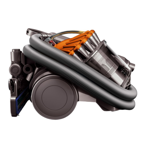
Service manual This manual is written specifically for Dyson trained engineers and covers the full DC23 range. The service instructions assume the engineer has the approved tools and test equipment with them. Contents Page Features and benefits Electrical safety testing... - Page 4 Service manual The full-sized cylinder with hygienic bin emptying Doesnʼt lose suction and captures more microscopic dust Combines Cyclone technology with a core separator an extra cyclonic stage between the outer and inner cyclones to separate particles as small as 0.5 micron from the Sits on the stairs airflow.
-
Page 5: Electrical Safety Testing
The following tests must be performed prior Motorhead variant to and upon completion of all repairs to Dyson floorcare products and before any functional checks. You must ensure that a full visual inspection of the product is completed prior to repair. -
Page 6: Electrical Overview
Service manual Test results If you cannot repair a product with an An insulation test reading of >2 MW is acceptable. insulation test reading of below 2MW you must inform the customer that the A reading of below 2 MW is not considered product is unsafe to use. -
Page 7: Wiring Schematic Motorhead Variant
Service manual Wiring schematic Motorhead variant... -
Page 8: Electrical Fault Diagnostic - Motorhead Variant
Service manual Electrical fault diagnostic - Motorhead variant Note: check ‘points’ refer to the wiring schematic on page 4. No power to either motor 1. Check for damage/electrical failure to the plug and powercord. 2. Carry out a resistance test across the fuse (UK only). 3. -
Page 9: Cable Rewind Replacement - Removal
Service manual General notes Disconnect the machine from the electrical outlet at all times during repair and test. Failure to do so could result in electric shock or personal injury. Wire colours may vary between territories. All screws used in DC23 are Torx T15 unless otherwise stated. - Page 10 Service manual 02 Push the hose bracket release catch to remove the hose and wand assemblies from the front of the product. Motorhead variant only 03 Press the release catch on the cyclone inlet to release the hose and wand assemblies from the product.
- Page 11 Service manual 05 Undo the two screws in the side of the product. 06 Undo the five screws in the upper chassis. 07 Lift off the upper chassis.
- Page 12 Service manual 08 Slide the cyclone inlet off the upper chassis.* 09 Disconnect the two wires from the switch. 10 Remove the switch actuator and spring from the switch housing.* *Not necessary if replacing the cable rewind only.
- Page 13 Service manual 11 Remove the switch from the switch housing.* 12 Remove the screw in the switch housing. 13 Remove the switch housing from the product. *Not necessary if replacing the cable rewind only.
- Page 14 Service manual Motorhead variant only 14 If the PCB assembly needs replacing, carefully detach all wires from it and remove it from the product. 15 Slide a large flat bladed screwdriver down the channel between the cable rewind assembly and the main chassis to activate the cable rewind release clip.
- Page 15 Service manual 17 Release the motor wire from the cable rewind assembly. 18 Unclip the cable rewind actuator from the product. 19 Slide the cable rewind actuator and spring out of the upper chassis.
- Page 16 Service manual 20 Remove the cable guard screw. 21 Insert a Torx T15 screwdriver into the detail at the bottom of the cable rewind actuator housing and lever down to release the cable guard from the upper chassis. 22 Release the cable from the upper chassis.
-
Page 17: Cable Rewind Replacement - Fitting
Service manual Cable rewind replacement - fitting 23 Locate the cable into the cable rewind housing. 24 Locate the cable guard onto the detail on the rear of the upper chassis. 25 Press the cable guard onto the upper chassis. Fit the screw on the underside. - Page 18 Service manual 26 Locate the cable rewind actuator and spring into the upper chassis. 27 Attach the motor wire onto the cable rewind. 28 Dress the wires neatly within the clips on the cable rewind holder.
- Page 19 Service manual 29 Lower the cable rewind into the side of the product ensuring the release mechanism locates within the channel. 30 Ensure any wires are located under the detail on the top of the cable rewind holder. 31 Dress all wires neatly within the channels provided.
- Page 20 Service manual Motorhead variant only 32 If previously removed, locate the PCB assembly onto the product. Carefully connect all wires. 33 Lower the switch housing onto the detail on the side of the chassis ensuring the wires are retained within the detail on the front of the housing.
- Page 21 Service manual 35 Attach the wires to the switch. 36 If previously removed push the on/off actuator onto the switch ensuring the lugs click into the switch housing. 37 Dress the switch wires into the channels provided on the switch housing.
- Page 22 Service manual 38 If previously removed slide the cyclone inlet onto the UMC. Motorhead variant only 39 Ensure the cyclone inlet cable is located into the channel provided on the front of the main chassis. 40 Lower the upper chassis onto the main body.
- Page 23 Service manual 41 Fit the five screws on the front of the product. 42 Fit the two screws on the side of the product. 43 Locate the rear wheel onto the side of the product. Press firmly to fit.
- Page 24 Service manual 44 Slide the hose into the cyclone inlet. 45 Clip the hose retainer onto the front of the product. 46 Replace the cyclone and the bin assemblies onto the product.
-
Page 25: Motor Bucket Assembly Replacement - Removal
Service manual Motor bucket assembly replacement - removal Before continuing the following parts should be removed as previously shown: Cable rewind and PCB assembly (pages 6-13) 47 Unlock the pre-filter cover fastener. 48 Open the pre-filter cover assembly. Should it need replacing it can be pulled firmly off the hinge points on the rear of the product. - Page 26 Service manual 50 Remove the four Philips screws from the pre-filter housing. 51 Remove the pre-filter housing. 52 Twist the the bleed valve cap to unlock it.* * Only necessary if replacing the bleed valve assembly.
- Page 27 Service manual 53 With the bleed valve cap unlocked all parts can be pulled away from the pre-filter housing. All parts can be fitted in reverse.* 54 Remove the post filter assembly. 55 Remove the four Torx T-10 screws from the side of the cable rewind assembly.
- Page 28 Service manual 56 Snip the connector clip off the end of the motor wiring assembly (Motorhead models only). Push the wiring grommet through the main chassis. 57 Remove the motor bucket from the product. 58 Remove the four screws from the top of the motor bucket.* * Only necessary if replacing the motor wiring assembly.
- Page 29 Service manual 59 Remove the six screws from the side of the motor bucket. Unclip the motor wires from the side of the bucket.* 60 Separate the two halves of the motor bucket.* 61 Separate the motor wires.* * Only necessary if replacing bleed valve assembly. All parts are offered together within the motor bucket assembly...
-
Page 30: Motor Bucket Assembly Replacement - Fitting
Service manual Motor Bucket assembly replacement - fitting 62 Connect the motor wiring assembly to the motor wires. 63 Locate the cable clips neatly within the fancase. 64 Fit the upper half of the motor bucket over the motor ensuring the motor wires are located within the slot. - Page 31 Service manual 65 Fit the four screws in the motor bucket. 66 Fit the six screws in the side of the motor bucket. 67 Neatly dress the motor wiring assembly under the clip and within the channels on the end of the motor bucket.
- Page 32 Service manual 68 Pull the motor wires through the hole in the main body. Ensure the grommet is adequately seated in the hole. 69 Locate the exhaust of the motor onto the detail in the main chassis. 70 Fit the four Torx T-10 screws.
- Page 33 Service manual 71 Fit the post filter assembly. 72 Fit the pre-filter housing. Fit the four Philips screws. 73 Fit the pre-filter assembly.
- Page 34 Service manual 74 If previously removed clip the pre-filter cover onto the hinge points on the side of the product. 75 Twist and lock the pre-filter cover fastener. 76 Attach the connector clip onto the ends of the motor wiring assembly (Motorhead models only).
-
Page 35: Main Chassis Replacement - Dismantle
Service manual Main chassis replacement - dismantle Before continuing the following parts should be removed as previously shown: Cable rewind and PCB assembly (pages 6-13) Motor bucket assembly (pages 22-26) 77 Prise the castor wheel and axle out of the castor body. 78 Prise the castor body off the base of the chassis. - Page 36 Service manual 80 Release the top edge of the exhaust seal from the main chassis. Release the tool storage and all parts attached to it from the main chassis. 81 Remove the screw and rear hose guide from the tool storage.* 82 Carefully remove the cyclone release catch spring.* *Only necessary if replacing any of the components attached to the tool storage.
- Page 37 Service manual 83 Prise the cyclone release catch out of the cyclone release catch housing.* 84 Remove the screw and cyclone release catch housing from the tool storage.* 85 Remove the screw and parking yoke from the tool storage.* *Only necessary if replacing any of the components attached to the tool storage.
- Page 38 Service manual 86 Remove the three screws in the duct cover. 87 Remove the duct cover and seal. 88 Pull the duct cover seal off the duct cover.
- Page 39 Service manual 89 Pull the cyclone exhaust seal off the main chassis.
-
Page 40: Main Chassis Replacement - Assemble
Service manual Main chassis replacement - assemble 90 Locate the duct cover seal onto the duct cover. One spot of glue should be applied to each side of the duct cover too hold the ends of the duct cover seal in place. 91 Fit the duct cover and seal onto the main chassis. - Page 41 Service manual 93 Locate the cyclone release catch housing onto the front of the tool storage. Fit the screw. Locate the spring onto the cyclone release catch. Insert the cyclone release catch into the housing ensuring the spring locates onto the cruciform in the cyclone release catch housing.
- Page 42 Service manual 96 Apply one spot of glue to the four locations shown. Fit the cyclone exhaust seal onto the main chassis. 97 Peel the top edge of the exhaust seal from the main chassis. Position the front of the tool storage onto the main chassis.
-
Page 43: Sub-Assemblies - Bin Assembly
Service manual Sub-assemblies - Bin assembly 99 Firmly pull back the bin base assembly to remove from the bin assembly. 100 The bin base seal can be replaced by firmly pulling it off the bin base assembly. When fitting ensure the seal is adequately seated around all edges and details. - Page 44 Service manual 102 To fit the bin base assembly locate the two lugs into the bin assembly and push firmly until clicked into place.
-
Page 45: Sub-Assemblies - Power Wand Hose Assembly
Service manual Sub-assemblies - Power wand hose assembly 103 To remove the wand handle from the power wand hose assembly, undo the two screws on the top of the wand. 104 Undo the two Torx T-8 screws on the rear of the wand handle. 105 Slide the wand handle out of the rear of the power wand hose assembly. - Page 46 Service manual 106 The wand handle cover can be replaced by removing the Torx T-8 screw in the rear of the cover. 107 With the screw removed carefully prise out from the rear using a thin, flat bladed screwdriver. Fit in reverse. 108 The wand cuff cover can be replaced if necessary by undoing the two screws shown and lifting...
- Page 47 Service manual 109 Before fitting a new cover, ensure all wires are located within the channels and retainers provided. 110 To fit, locate the detail on the rear of the cover under the lip on the wand. Lower the cover onto the wand.
-
Page 48: Sub-Assemblies - Power Floor Tool - Dismantle
Service manual Sub-assemblies - Power floor tool - dismantle 111 The stow wheel or axle can be replaced by prising out the stow using a thin, flat bladed screwdriver. To fit, push both parts firmly into the stow. 112 To replace the stow neck cover, stow microswitch cam or spring remove the two short screws in the cover. - Page 49 Service manual 114 Carefully prise the microswitch cam and spring out of the neck. 115 When fitting the spring, ensure the tail of the spring locates into the channel in the microswitch cam. 116 Locate the pillar on the cam into the hole in the side of the neck.
- Page 50 Service manual 117 If either outer wheel hub, glamour cap or the axle need replacing, prise the relevant glamour cap off the wheel hub using a thin, flat bladed screwdriver. 118 Carefully remove the e-clip and washer. 119 Slide the wheel hub off the axle.
- Page 51 Service manual 120 The axle, outer wheel hub, glamour cap and remaining washers can then be removed from the side of the floor tool if necessary. 121 Fit in reverse ensuring all washers are fitted (two on either side of each wheel). 122 The internal hose can be replaced by simply lifting out the top of the floor tool.
- Page 52 Service manual 123 Turn the endcap fasteners counter-clockwise using a large, flat bladed screwdriver or coin. 124 Twist the endcap assemblies off the sides of the brush housing. 125 Slide each half of the brushbar assembly out of the brush housing.
- Page 53 Service manual 126 The soleplate wheels or axles can be prised out from the soleplate assembly if necessary using a thin, flat bladed screwdriver. To fit, firmly press both parts into the soleplate assembly. 127 Undo the seven Philips screws in the soleplate assembly.
- Page 54 Service manual 129 The bumper strip can be replaced by pushing very firmly away from the front of the brush housing. 130 Undo the three screws in the brushbar motor cover lower. 131 Lift the brushbar motor cover lower off the brushbar motor cover.
- Page 55 Service manual 132 Disconnect the two brushbar motor wires from the connectors. 133 Carefully release the brushbar microswitch loom from the rubber retainer on the rear of the brushbar motor. 134 Release the brushbar motor from the brushbar motor front mount.
- Page 56 Service manual 135 Remove the brushbar motor from the brush housing. Note: it may be necessary to use a screwdriver to carefully ease the motor out. 136 Carefully prise the brushbar microswitch holder off the retaining peg on the brushbar motor cover.
- Page 57 Service manual 138 If the brushbar actuator needs replacing, release the lip of it firmly from the brushbar motor cover using a large, flat bladed screwdriver. 139 Undo the two long screws in the underside of the brushbar motor cover. 140 Lift the gimble cover off the top of the brushbar motor cover.
- Page 58 Service manual 141 Undo the two screws in the top of the brushbar motor cover. 142 If the brush housing needs replacing, slide it away from the front of the brushbar motor cover. Remove the brushbar motor front mount from the front of the brush housing.
-
Page 59: Sub-Assemblies - Power Floor Tool - Assemble
Service manual Sub-assemblies - Power floor tool - assemble 143 Slide the brush housing under the brushbar motor cover and into the neck. Refit the two screws. 144 Ensure all wires are correctly located within the neck and can move freely. 145 Locate the rear of the of the gimble cover into the neck. - Page 60 Service manual 146 Locate the front of the brushbar actuator into the top of the brushbar motor cover. Force the rear of the actuator into the cover Turn the floor tool over and locate the lip of the actuator over the ledge in the underside of the brushbar motor cover.
- Page 61 Service manual 149 Firmly press the brushbar microswitch holder over the retaining peg on the brushbar motor cover. 150 Locate the brushbar motor front mount into the front of the brush housing.
- Page 62 Service manual Brushbar microswitch loom Ensure the motor wires sit under the motor brushes Brushbar motor end mounts Transmission manifold 151 Ensure the brushbar motor wires are looped under the motor brushes. Important: Hold the brushbar microswitch loom out of the way. Lower the brushbar into the brushbar motor cover. When correctly located the brushbar motor end mounts will sit onto the shelves.
- Page 63 Service manual 153 Attach the motor wires to the connectors. Ensure the wires are retained in the channels on the connector housing. 154 Lower the brushbar motor cover lower onto the brush housing. Fit the three screws. 155 Ensure if previously removed that all lengths of ropeseal are fitted into the edges of the brush housing.
- Page 64 Service manual 156 Press the bumper strip firmly onto the front of the brush housing if previously removed. 157 Lower the soleplate assembly onto the brush housing. 158 Locate the two halves of the brushbar assembly into the transmission of the brushbar motor.
- Page 65 Service manual 159 Locate the endcap assemblies onto the ends of the brushbar assembly. Twist into position on the brush housing. 160 Twist the endcap fasteners clockwise to lock in position.
-
Page 66: Main Body
Service manual Main body Cable Rewind Actuator Spring On/Off Actuator Switch Spring Screw Switch Housing Cable Rewind Cyclone Release Catch Assy Spring Screw Cyclone Release Catch Housing Upper Chassis Rear Hose Guide Screw Tool Storage Screw Park Yoke (Motorhead) Cyclone Inlet (Passive) Park Yoke Cyclone Inlet... -
Page 67: Cyclone And Bin Assemblies
Service manual Cyclone and bin assemblies Cyclone Assy Bin Assy Bin Base Seal FDC/IDC Seal Bin Base Assy... -
Page 68: Wand And Hose Assemblies
Service manual Wand and hose assemblies Screw Stubborn Dirt Brush Assy Wand Handle Cover Wand Handle Universal Fit Adaptor Screw Flexi Crevice Screw Tool Assy Universal Fit Adaptor Power Wand Hose Assy Hard Floor Tool Assy Wand Cuff Cover Screw Mini Turbine Head Assy Wand Handle... -
Page 69: Power Floor Tool Assembly
Service manual Power floor tool assembly Screw Gimble Cover Axle Brushbar Actuator Washer Spring Glamour Cap Stow Microswitch Cam E-Clip Screw Outer Wheel Hub Stow Neck Cover Internal Hose Assy Stow Wheel Axle End Cap Assy Right Brushbar Motor Brush Housing Brushbar Motor End Mount Ropeseal...