Table of Contents
Advertisement
Quick Links
Advertisement
Table of Contents

Related Manuals for Teledyne Lecroy WaveSurfer 3104Z


Summary of Contents for Teledyne Lecroy WaveSurfer 3104Z
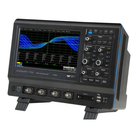
- Page 1 WaveSurfer 3000z Oscilloscopes Getting Started Guide...
- Page 2 Teledyne LeCroy documentation for internal educational purposes. Teledyne LeCroy is a trademark of Teledyne LeCroy, Inc. Other product or brand names are trademarks or requested trademarks of their respective holders. Information in this publication supersedes all earlier versions. Specifications are subject to change without notice.
-
Page 3: Table Of Contents
Welcome Thank you for buying a Teledyne LeCroy product. We’re certain you’ll be pleased with the detailed features unique to our instruments. This guide is intended to help you set up a WaveSurfer 3000z oscilloscope and learn some basic operating procedures, so you're quickly working with waveforms. -
Page 4: Introduction
A fast waveform update rate used in conjunction with history mode, Materials List WaveScan, sequence sampling mode, and mask testing facilitates outstanding waveform anomaly detection. Check that you have all the parts listed here. Contact Teledyne LeCroy immediately if any part is missing. Biggest Touch Screen Display •... -
Page 5: Safety
SAFETY Safety Precautions Observe generally accepted safety procedures in addition to the Use proper power cord. Use only the power cord shipped with this precautions listed here. instrument and certified for the country of use. Operating Environment Maintain ground. This product is grounded through the power cord Temperature 0 °C to 50 °C grounding conductor. -
Page 6: Overview
OVERVIEW Front of Oscilloscope A. Touch Screen Display B. Front Panel C. Ground and Calibration Terminals D. USB 2.0 Ports E. Mixed Signal Interface F. Channel Inputs G. Rotating / Tilting Feet H. Power On/Off Button 934416-00 Rev A... -
Page 7: Powering On/Off
OVERVIEW Powering On/Off The touch screen display is the principal viewing and control center of Connect the line cord rated for your country to the AC power inlet on the the oscilloscope. See p.10 for an overview of its components. back of the instrument, then plug it into a grounded AC power outlet. -
Page 8: Back Of Oscilloscope
OVERVIEW Back of Oscilloscope A. Built-in Carrying Handle B. WaveSource Output C. Kensington Lock D. Micro SD Card (removable drive) E. EXT Trigger Input F. AUX Output G. VGA Video Output to external monitors H. Ethernet Port I. USBTMC Port for remote control J. -
Page 9: Connecting To External Devices/Systems
OVERVIEW Connecting to External Devices/Systems After start up, configure external connections using the menu options listed below. See the WaveSurfer 3000z Oscilloscopes Operator’s Manual WaveSurfer 3000z is preset to accept DHCP network addressing over a for more detailed instructions. TCPIP connection. Just connect a cable from the Ethernet port on the back panel to a network access device. - Page 10 WaveSurfer 3000z oscilloscopes are compatible with the included passive Each flying lead has a signal and a ground connection. A variety of ground probes and most Teledyne LeCroy ProBus active probes that are rated for extenders and flying ground leads are available for different probing the oscilloscope’s bandwidth.
-
Page 11: Front Panel
OVERVIEW Front Panel Most of the front panel controls duplicate functionality available through the touch screen display. They are covered in more detail in the Basics section and in the WaveSurfer 3000z Oscilloscopes Operator’s Manual. Shortcut buttons arranged across the top of the front panel give quick access to commonly used functions. -
Page 12: Touch Screen Display
OVERVIEW Touch Screen Display The entire display is a capacitive touch screen. Use your finger or a capacitive stylus (not included) to touch, double-touch, touch-and-drag, or draw a selection box. Many controls that display information also work as “buttons” to access other functions. If you have a mouse installed, you can click anywhere you can touch to activate a control;... - Page 13 OVERVIEW The Action toolbar on the main Channel, Math, and Memory dialogs A menu bar of drop-down menus lets you access set up dialogs and other offers shortcuts to common actions so you don’t have to leave the functions. All functionality can be accessed through the menu bar. underlying dialog.
-
Page 14: Basics
BASICS Changing the Display Grid Mode The grid is 8 Vertical divisions representing 256 Vertical levels and 10 The grid area can contain multiple grids, each representing the full Horizontal time divisions. The value represented by each division depends number of Vertical levels, so vertical precision is always maintained. on the scale settings of the traces that appear on it. - Page 15 BASICS Line and Intensity Grid Intensity makes the grid lines dimmer or brighter relative to the trace. The front panel Intensity button sets the Adjust knob to control the trace intensity You can also apply Axis Labels to show the value currently represented setting.
-
Page 16: Working With Traces
BASICS Working with Traces Active vs. Inactive Trace The easiest way to turn on a trace is to press the front panel C1-C4, Math, and Zoom buttons. Provided there is a signal, a waveform appears on the Although several traces may be open and appear on the display, only one at grid, a new descriptor box opens at the bottom of the grid area, and the a time is active. - Page 17 BASICS Adjusting Setups Touch & Drag On trace setup dialogs, many entries can be made by selecting from the pop- Just as you change the display by using the setup dialogs, you can up menu that appears when you touch a control. change the setups by moving different display objects.
-
Page 18: Vertical
BASICS Vertical Vertical controls adjust analog traces along the Y axis. Traces represent eight Vertical divisions of the source signal at the selected number of Volts or Amperes per division. The zero level is at the center grid line unless you add positive or negative Offset. The front panel Volts knob also controls the Vertical Scale of zoom, math, and memory traces. - Page 19 BASICS From the Touch Screen Touch Channel descriptor once to reactivate the trace, twice to reopen the Cn dialog. Enter Attenuation for non-Teledyne LeCroy probes. Optionally, change Vertical Unit of grid from Volts to Amperes. Refine Volts/div or Offset. Enter signal Enter Coupling and Bandwidth.
-
Page 20: Digital
BASICS Digital On instruments with a Mixed Signal probe option, Digital selections are added to the Vertical menu, and the front panel Vertical knobs control active Digital line and bus traces. From the Front Panel Digital Descriptor Box Turn Offset to # Digital Lines in Group raise/lower group Vertical Position,... - Page 21 BASICS From the Touch Screen On the Logic Setup tab, choose a standard Logic Family, or enter a custom Threshold. Separate controls allow you to set different values for each lead bank. Touch Digital descriptor once to activate digital trace. twice to open Digitaln dialog.
-
Page 22: Horizontal (Timebase)
BASICS BASICS Horizontal (Timebase) Horizontal controls adjust traces along the X axis. Analog traces usually represent one acquisition of the source signal for 10 divisions of the selected Time per division. The trigger event is shown at the center of the grid, unless you add positive or negative Delay time. The front panel Time knob also controls the Horizontal Scale of zoom, math and memory traces, allowing you to "zoom in"... - Page 23 BASICS From the Touch Screen Touch the Timebase descriptor to open Timebase setup dialog. Refine Time/div. Select Sampling Mode. When Average, also enter the number of Sweeps. Optionally, enter Delay, Set To Zero Enter Maximum Points (negative) time before or removes Delay.
-
Page 24: Triggers
BASICS Triggers Triggers tell the oscilloscope when to perform an acquisition. The acquisition starts as soon as the trigger is armed and all trigger conditions are met, unless postponed by a Holdoff count of time or number of trigger events. Trigger types and modes are described at more length in the WaveSurfer 3000z Oscilloscopes Operator’s Manual. - Page 25 BASICS From the Touch Screen Touch Trigger descriptor to open Trigger setup dialog. Choose trigger Source channel. Open tab to set trigger Holdoff. Choose trigger Type. Set trigger Level, Set other conditions, Icon summarizes the or Find Level based trigger selections. such as Slope and Coupling on the input signal.
-
Page 26: Zoom
BASICS Zoom Zoom traces display a magnified portion of another trace. Any trace can be zoomed, although Zoom is most useful for channel traces, as it allows you to see the source at the original Timebase at the same time as the Zoom "close up." From the Front Panel When you use the front panel Zoom button, a new Zoom trace is created for every open trace, showing a 10x magnification of the source trace. - Page 27 BASICS From the Touch Screen Draw a Zoom box over a Zoom descriptor portion of the source trace. opens Zoom dialog to make other Repeat on another section to adjustments. reposition the Zoom trace. On the source trace setup dialog, touch Action Toolbar Zoom button to create a new zoom of just that source trace.
-
Page 28: Cursors
BASICS Cursors Cursors set measurement points on the Vertical or Horizontal axis of a trace (or both). The five preset cursor types are described in more detail in the WaveSurfer 3000z Oscilloscopes Operator’s Manual. All show the absolute value where the cursor intersects the waveform and the delta of the two lines. From the Front Panel Apply cursor. -
Page 29: Measurements & Statistics
BASICS Measurements & Statistics Measurements are waveform parameters that can be expressed as numerical values, such as amplitude or frequency. You can set up-to-six simultaneous measurements on one or more traces and view the active readout in a table below the grid. Statistics can be added to the readout along with histicons, a miniature histogram of the statistical distribution. -
Page 30: Math
BASICS Math Math creates a new trace that displays the result of applying a mathematical function (e.g., Sum, Product, FFT) to one or more source traces. Operations can be chained by using one math function as a source for the other. The math trace always opens in a separate grid from the source and can be viewed along side it. -
Page 31: Memories (Reference Waveforms)
BASICS Memories (Reference Waveforms) Memories are traces stored for reference. They can be recalled to the display for comparison with other traces. A memory can be zoomed or measured for better analysis of historical data. You can store up-to-two internal memories (M1-M2). After that, new memories will overwrite previously stored data. Internal memories persist only until the oscilloscope is rebooted. -
Page 32: Wavesource
BASICS WaveSource The optional WaveSource Waveform Generator allows you to output multiple types of waveform signals, including arbitrary waveforms, from the WaveSurfer 3000z. To use it, just connect a BNC cable from the WaveSource output on the back of the oscilloscope to the input device and set up the waveform on the WaveSource dialog. -
Page 33: Saving And Sharing Data
BASICS Saving and Sharing Data Setup, Waveform and Table Data Use the oscilloscope File menu options to save and recall data. See the The current oscilloscope configuration can be saved to internal setup WaveSurfer 3000z Oscilloscopes Operator’s Manual for more information on panels or setup (.LSS) files and later recalled. -
Page 34: Maintenance
MAINTENANCE Cleaning Calibration Clean the outside of the WaveSurfer 3000z using a soft cloth moistened The WaveSurfer 3000z is calibrated at the factory prior to being shipped. with water or isopropyl alcohol solution. Do not use harsh or abrasive The calibration is run at 23 °C (± 2 °C) and is valid for temperatures ± 5 °C cleansers. -
Page 35: Firmware Updates
MAINTENANCE Firmware Updates Language Selection Free firmware updates are available periodically from the Teledyne LeCroy To change the language that appears on the oscilloscope touch screen, from website at teledynelecroy.com/support/softwaredownload. Registered the menu bar, choose Utilities > Preference Setup > Preferences and make users will receive email notification when a new update is released. -
Page 36: Service
Return shipments must be prepaid. Teledyne LeCroy cannot accept COD Service Centers or Collect shipments. We recommend air freighting. Insure the item you’re For a complete list of Teledyne LeCroy offices by country, including our returning for at least the replacement cost. . sales and distribution partners, visit: teledynelecroy.com/support/contact... -
Page 37: Reference
See p.30. The product is warranted for normal use and operation, within specifications, for a period of three years from shipment. Teledyne LeCroy will either repair or, at our The Spectrum Analyzer option (WS3K-SPECTRUM-1) simplifies setup option, replace any product returned to one of our authorized service centers within and use of the oscilloscope for analyzing frequency-dependent effects. -
Page 38: Certifications
1 To ensure compliance with all applicable EMC standards, use high-quality shielded interface cables. 2 Emissions which exceed the levels required by this standard may occur when the instrument is Teledyne LeCroy certifies compliance to the following standards as of the time of publication. Please see the EC Declaration of Conformity connected to a test object. - Page 39 Many countries prohibit the disposal of waste outlets and similar). electronic equipment in standard waste receptacles. For more information about proper disposal and recycling of your Teledyne LeCroy product, • Measuring Circuit Terminals: No rated measurement category.
- Page 40 934416-00 Rev A, January, 2022 © 2022 Teledyne LeCroy, Inc. All rights reserved.