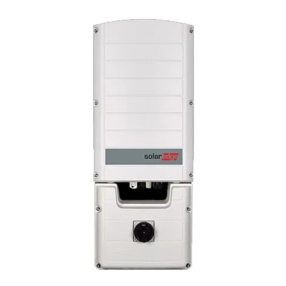
Summary of Contents for SolarEdge SE K-AU I Series
- Page 1 Three Phase Inverter with SetApp Configuration PN: SEXXK-AUXXIXXXX Quick Installation Guide For Australia Version 1.1...
- Page 2 This symbol appears at grounding points on the Turn ON/OFF the main circuit SolarEdge manuals and equipment. board AC switch, and wait 5 minutes WARNING! Denotes a hazard. It calls attention to a 9.0 N*m / 6.6 ft.*lb...
-
Page 3: Installing The Power Optimizers
Step Installing the Power Optimizers Verify string design with Designer 10 mm / 0.4" 25 mm / 1" (P860, M1600) 10 mm / 0.4" 25 mm / 1" (P860, M1600) 12.7 mm / 0.5” M6 (1/4’’) or M8 (5/16”) stainless steel 9.5 N*m / 7 lb*ft 10 mm / 0.4" 25 mm / 1" 10 mm / 0.4"... - Page 4 Step 1 Scan stickers using Mapper Complete site registration and physical layout in the monitoring platform MAN-01-00695-1.1...
- Page 5 Step 1 Extension cables (4mm /1.6" between optimizers are allowed between rows and Input from module around obstacles 2:1 series connection Output to string Use a dual input optimizer (P800p) for parallel connection of two PVs . Use a branch cable to connect two PVs to a single input optimizer. MAN-01-00695-1.1...
- Page 6 Step 1 Check string polarity and measure each string’s voltage to verify 1±0.1V per optimizer Example: 8 optimizers = ~8V To minimize electromagnetic interference (EMI), make sure to minimize the distance between the positive and negative DC cables MAN-01-00695-1.1...
-
Page 7: Installing The Inverter
Step Installing the Inverter On mesh fence On mesh fence Indoor Outdoor 40 cm / 16” 40 cm / 16” 1 15 cm / 6” 10 cm / 4” 10 cm / 4” 5 cm / 2” 30 cm / 11.8” 20 cm / 8” where annual average high temperature is above 25˚C / 77˚F 40 cm / 16”... - Page 8 Step 2 4.0 N*m / 3 lb.*ft. CAUTION! Do not block Airflow Use 3/4” or 1” Unibit drill to create holes for AC and DC conduits MAN-01-00695-1.1...
-
Page 9: Connecting The Pv Array
Step Connecting the PV Array 6-35mm 25 mm Solid, stranded or fine stranded conductor. When using a stranded copper wire, use of ferrule is at the installer discretion. Bi-metal ferrule must be used for aluminum conductor. PV Solar Arrays Combiner To add strings in parallel, use external For inverters up to SE25K ≤300m (For SE25K and above: ≤700m) combiner box... - Page 10 Step Connecting to the AC Grid 1.2-1.5 N*m Connect PE first L1 L2 L3 N PE 4 -16 mm 10-11 mm When using a stranded wire, use of ferrule is at the installer discretion Rated currents: I solar at 40°C and I solar at 60°C shade ambient air temperature is 55A MAN-01-00695-1.1...
-
Page 11: Setting Up Communication
Step Setting up Communication Built-in: 1. Ethernet (see page 11) 2. RS485 (see page 11) Optional Wi-Fi (Requires antenna) Wi-Fi (L’antenne est nécessaire) Wi-Fi (Antenne is vereist) Wi-Fi (È necessaria l’antenna) Wi-Fi (Antenne wird benötigt) MAN-01-00695-1.1... - Page 12 Step 5 Wi-Fi antenna PRI Control RS485-2 RS485-1 Ethernet Scan QR for communication options Scan QR for troubleshooting MAN-01-00695-1.1...
- Page 13 Step Creating Ethernet (LAN) Connection LAN Router 5.5 N*m / 4 ft.*lb MAN-01-00695-1.1...
- Page 14 Step 6 T568B T568A Wire Color 10Base-T Signal RJ45 100Base-TX Signal Pin # T568B T568A White/Orange White/Green Transmit+ Orange Green Transmit- White/Green White/Orange Receive+ Blue Blue Reserved White/Blue White/Blue Reserved Green Orange Receive- White/Brown White/Brown Reserved Brown Brown Reserved ¹ The inverter connection does not support RX/TX polarity change. Supporting crossover Ethernet cables depends on the switch capabilities MAN-01-00695-1.1...
- Page 15 Step Creating RS485 Bus Connection Master Slaves (up to 31 inverters) RS485-1 RS485-1 RS485-1 RS485-1 B A G B A G B A G B A G < 1km /3300 ft. Min. 3-wire shielded twisted pair (a 4-wire cable may be used). Wire cross-section: 0.2-1 mm² MAN-01-00695-1.1...
- Page 16 Step 7 Move SW1 switch to ON (up) to terminate first and last inverters on RS485 bus G - Green wire A - Blue/White wire B - Blue wire 4 N*m / 3 ft.*lb MAN-01-00695-1.1...
- Page 17 Step First time SetApp Installation Login: 1. Open SetApp and follow the instructions 2. Log-in with your monitoring Username and password MAN-01-00695-1.1...
- Page 18 Step Activating SetApp creates a Wi-Fi connection with the inverter Follow the SetApp instructions Scan inverter QR code; for RS485 bus, scan master first MAN-01-00695-1.1...
- Page 19 Step Commissioning Set Country and Language Set all other parameters From the Commissioning menu, select Set communication to the monitoring Pairing to pair the optimizers with the inverter platform and to the other inverters MAN-01-00695-1.1...
-
Page 20: Viewing System Status
Step Viewing System Status SetApp Status screen Monitoring platform Main LEDs Indications Status Inverter SN 07318000C Power Voltage Frequency XX kW XXX Vac XX Hz Optimizers Connected Communication S_OK P_OK Ethernet 30 of 30 Status Switch Production Cos Phi Limit Country 1.00 No Limit Australia Voltage... - Page 21 Support Contact Information If you have technical problems concerning SolarEdge products, please contact us: https://www.solaredge.com/service/support Subject to change without notice. Copyright © SolarEdge Inc. All rights reserved. February 2022.


