Table of Contents
Advertisement
Quick Links
510062
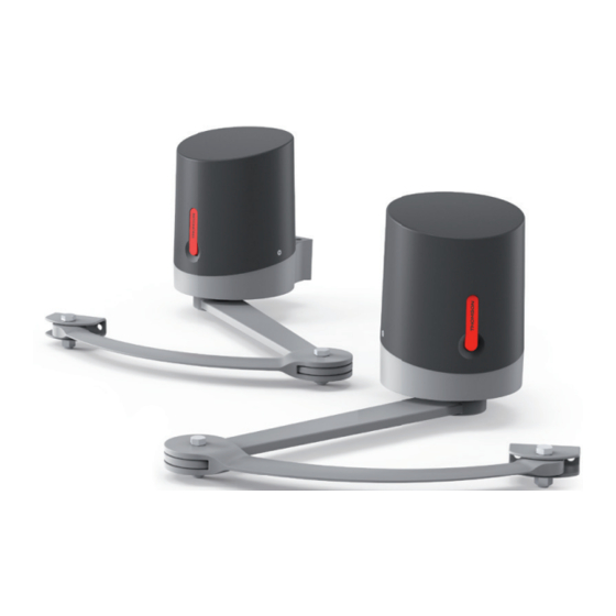
SESAME 250 - CONNECT
EN
Pivoting arm motor drive kit
For 2-panel swing gates
2,50m / 250kg
per panel
Solar
/ 250kg
anel
OPTION
24V
Solar
OPTION
24V
Solar Power
emergency
battery
OPTION
0kg
Solaire
nt
V1
24V
Solar
OPTION
24V
Solar Power
emergency
battery
Solar Power
emergency
battery
24V
OPTION
Batterie
de secours
Solar Power
emergency
battery
www.mythomson.com
0 892 701 369
Available on the
Free available on
Google Play
0,35 € / min
V6
Advertisement
Table of Contents

Related Manuals for THOMSON SESAME 250

Summary of Contents for THOMSON SESAME 250
- Page 1 510062 SESAME 250 - CONNECT Pivoting arm motor drive kit For 2-panel swing gates Solar Solar Power 2,50m / 250kg per panel emergency OPTION battery Solar Solar Power / 250kg anel OPTION emergency battery Solar Solar Power emergency OPTION battery...
-
Page 2: Table Of Contents
MOTOR DRIVE FOR 2-PANEL GATES - CONNECT CONTENTS A - SAFETY INSTRUCTIONS 1 - OPERATING PRECAUTIONS 2 - INSTALLATION PRECAUTIONS 3 - MAINTENANCE AND CLEANING 4 - RECYCLING B - PRODUCT DESCRIPTION 1 - KIT CONTENTS 2 - EQUIPMENT REQUIRED (NOT INCLUDED) C - INSTALLATION 1 - HAZARD ANALYSIS 1.1 - Regulations... - Page 3 3 - INSTALLING THE MOTOR DRIVE 3 .1 - Installing the stops 3.2 - Assembling the pivoting arm 3.3 - Installing the motors - for opening towards the inside of the property 3.4 - Installing the motors - for opening towards the outside of the property 4 - INSTALLING THE FLASHING LIGHT 5 - INSTALLING THE SET OF PHOTOCELLS 5 .1 - Opening outwards 5 .2 - Opening inwards 5.3 - 2 set of photocells (optional) 6 - CONNECTIONS 6 .1 - The mains electricity 6.2 - Motors 6.3 - Flashing light...
- Page 4 MOTOR DRIVE FOR 2-PANEL GATES - CONNECT CONTENTS continued D - BEGINNING OPERATION 1 - SETTINGS INTERFACE 2 - BASIC SETTINGS (MENU 1) 2 .1 - Menu structure 2 .2 - Photocell alignment procedure (optional) 2 .3 - Operating mode 2 .4 - Time delay 2 .5 - Motor force 2 .6 - Speed 2 .7 - Self-learning 2 .8 - Programming remote controls...
- Page 5 5 - PHOTOCELLS 5 .1 - Obstacle detection 6 - MANUAL MOVEMENT F - MAINTENANCE AND UPKEEP 1 - MAINTENANCE WORK 2 - OPERATING INDICATORS 2.1 - History of events and error codes 2.2 - Manual control 2.3 - Total reset 2.4 - Replacing the remote control battery 2.5 - Replacing the power fuse G - TECHNICAL AND LEGAL INFORMATION 1 - COMPATIBLE ACCESSORIES 2 - TECHNICAL CHARACTERISTICS 3 - WARRANTY...
-
Page 6: A - Safety Instructions
MOTOR DRIVE FOR 2-PANEL GATES - CONNECT A - SAFETY INSTRUCTIONS In our efforts to continually improve our products, • D o not manually activate the gate when the we reserve the right to make any changes to the motor drive is not disengaged from the gate. technical, functional, or aesthetic characteristics • A vidsen cannot be held liable for any use that related to their development. does not comply with the instructions in this This motorised gate, and its manual, were manual and causes damage. -
Page 7: Maintenance And Cleaning
MOTOR DRIVE FOR 2-PANEL GATES - CONNECT A - SAFETY INSTRUCTIONS • I f installation does not correspond to one of the 4 - RECYCLING cases shown in this manual, you must contact us so that we can provide all the components Disposing of used batteries in necessary for smooth installation with no risk of household waste is strictly forbidden. -
Page 8: B - Product Description
MOTOR DRIVE FOR 2-PANEL GATES - CONNECT B - PRODUCT DESCRIPTION 1 - KIT CONTENTS N L O SC S N L O SC S Main motor with electronic card M8 CHC – L30 screw Secondary motor M8 washer Remote control M8 spring washer Flashing light and screws M12 locknut Rear arm M10 nut Front arm M10 spring washer Post mounting bracket M10 washer Gate mounting bracket M10 - L120 fastening pin M12 – L40 screw... -
Page 9: Equipment Required (Not Included)
MOTOR DRIVE FOR 2-PANEL GATES - CONNECT B - PRODUCT DESCRIPTION 2 - EQUIPMENT REQUIRED (NOT INCLUDED) The tools and screws required for the installation must be in good condition and compliant with applicable safety standards. 1 measuring tape 1 x 19mm box spanner 1 spirit level 1 pencil and 1 x 13mm box spanner 1 drill 1 x 13mm spanner 1 flat head screwdriver 1 Phillips screwdriver Flashing light Motor Photocells Attachment of Attachment Attachment of the the flashing light of the motors brackets on the gate: Ø12 onto the post on the posts Choose a screw/ Ø6... -
Page 10: C - Installation
MOTOR DRIVE FOR 2-PANEL GATES - CONNECT C - INSTALLATION 1. HAZARD ANALYSIS 1.2. Specifications of the gate to motorise 1.1. Regulation This motor drive can automate swing gates up to 2.50m wide and 2.80m high and weighing 250kg. Installation of a motorised gate or a motor drive on an existing gate within the framework These maximum dimensions and weights are for an openwork-type gate and for use in an... -
Page 11: Safety Rules
MOTOR DRIVE FOR 2-PANEL GATES - CONNECT C - INSTALLATION 1.4. Safety rules The actual opening of a gate may create dangerous situations for people, goods and vehicles in the vicinity that by nature, cannot always be avoided by design. The possible hazards depend on the state of the gate, the manner in which it is used and the installation site. After having checked that the gate to be motorised complies with the requirements given in this chapter and before beginning the installation, a hazard analysis of the installation must be conducted in order to eliminate all dangerous situations or to indicate them if they cannot be eliminated. 2. ELIMINATION OF HAZARDS The hazards posed by a two-panel motorised gate, as well as the adapted solutions to eliminate those hazards, are as follows: 2.1. -
Page 12: Between The Panels And The Fixed Parts Close To Each Other
MOTOR DRIVE FOR 2-PANEL GATES - CONNECT C - INSTALLATION Hazard Solution gate gate gate 5mm 50mm maximum hazardous zone minimum view in profile 2.3. Between the panels and the fixed parts close to each other Depending on the configuration of the site where the motorised gate is installed, there may be confinement areas between the panels in open position and the fixed parts close to them. To remove these areas, it is mandatory to leave a safe distance of 500mm between the fixed part and the moving parts of the motorised gate. -
Page 13: Prevention Of Other Hazards
MOTOR DRIVE FOR 2-PANEL GATES - CONNECT C - INSTALLATION 2.4. Prevention of other hazards The body of a switch with no lock must be located in direct view of the driven part but away from moving parts. Unless it operates with a key, it must be installed at a minimum height of 1.5m and must not be accessible to the public. After installation, ensure that the components of the gate do not hang above a footpath or public access road. 3. INSTALLING THE MOTOR DRIVE The motor drive must be installed by qualified personnel, in compliance with all the indications provided in the “General warnings.” Before starting installation, ensure that: • Hazards can be minimised by following the recommendations under the Chapter “Hazard analysis.” • The desired use has been correctly defined. • T he gate complies with the specifications provided in the Chapter “Specifications of the gate to motorise.”... -
Page 14: Installing The Stops
MOTOR DRIVE FOR 2-PANEL GATES - CONNECT C - INSTALLATION Tip: Position the motor containing the electronic card on the post where the 230V electrical supply is located. If the 230V electrical supply is already located on the left post, the connections do not need to be reversed. If the electrical supply is located on the right post, it is sufficient to reverse the motor connection polarity in order to reverse the direction of rotation with respect to the assembly described in these instructions (normal mounting with motor and electronic card on the left). List of cables: Connection Cable Max length Cable 3 x 2.5mm (more than 30m long) 230Vac power line Unlimited Cable 3 x 1.5mm (less than 30m long) Flashing light Cable 2 x 0.5mm Secondary motor 2 x 1.5mm² cable Reception photocell (RX) 4 x 6/10 cable Transmission photocell (TX) 4 x 6/10 cable 3.1. Installing the stops This gate motor drive is a self-locking motorisation system. Your 2-panel gate must be equipped with a central stop and side stops (not included). -
Page 15: Assembling The Pivoting Arm
MOTOR DRIVE FOR 2-PANEL GATES - CONNECT C - INSTALLATION If the positive distance D is greater than 200 mm or if distance D is negative, the configuration of the posts must be adjusted. Determine the opening angle of each panel based on the data in the following table. The opening angle may be different for each panel but must never be less than 40°. central stop For Distance D opening up to (in mm) 90° -50 < D < 200 98° -50 < D < 150 105° -50 < D < 100 opening opening side... -
Page 16: Installing The Motors - For Opening Towards The Inside Of The Property
MOTOR DRIVE FOR 2-PANEL GATES - CONNECT C - INSTALLATION Note: do not overtighten the parts together, the different pivoting parts must be able to turn freely. 3.3 - Installing the motors - for opening towards the inside of the property • P lace the mounting brackets against the posts, 14mm above the rigid part of the gate where the ends of the pivoting arms will be fastened. - Page 17 MOTOR DRIVE FOR 2-PANEL GATES - CONNECT C - INSTALLATION • U se plugs and screws that are suitable for the post material (example: for concrete, use ø12mm plugs and ø8mm lag screws with a length of 80mm). After tightening, the mounting bracket must be completely horizontal and 14mm above the middle of the rigid part of the gate. Make sure not to weaken the posts.
- Page 18 MOTOR DRIVE FOR 2-PANEL GATES - CONNECT C - INSTALLATION • P osition the bracket on the post (using distance X) and mark the locations of the holes. 115 mm 12mm bit for 12 plugs • O pen the cover of the motors...
- Page 19 MOTOR DRIVE FOR 2-PANEL GATES - CONNECT C - INSTALLATION • F asten the motors on the mounting brackets Screw 11 Washer 18 www.mythomson.com Spring washer 17 Nut 16 • A ssemble the pivoting arms and motors Washer 12 Washer 14 Screw 10...
- Page 20 MOTOR DRIVE FOR 2-PANEL GATES - CONNECT C - INSTALLATION • Motor disengagement • Disengage the motors in order to manually manoeuvre the arms • Close the gate by pressing it firmly against the central stop. • P osition the pivoting arms against the gate at a distance of 75cm and mark the location of the holes on the gate. Important: The ends of the right arms should be at the middle of the rigid part of the gate so that the pivoting arms are completely horizontal.
- Page 21 MOTOR DRIVE FOR 2-PANEL GATES - CONNECT C - INSTALLATION • Remove the gate bracket from the arm in order to fasten it to the gate. • Use screws and nuts that are suitable for the gate material. • Reassemble the end of the arm and the gate bracket. www.mythomson.com Important: At this point in the installation, the motors are disengaged. The gate may be set in motion by the wind or an external push. Be careful or block the gate to avoid any hazards during the rest of the installation. ž Or engage the motors:...
-
Page 22: Installing The Motors - For Opening Towards The Outside Of The Property
MOTOR DRIVE FOR 2-PANEL GATES - CONNECT C - INSTALLATION 3.4 - Installing the motors - for opening towards the outside of the property • P lace the mounting brackets against the posts, 14mm above the rigid part of the gate where the ends of the pivoting arms will be fastened. Inner side of the property • U se plugs and screws that are suitable for the post material (example: for concrete, use ø12mm plugs and ø8mm lag screws with a length of 80mm). After tightening, the mounting bracket must be completely horizontal and 14mm above the middle of the rigid part of the gate. Make sure not to weaken the posts. - Page 23 MOTOR DRIVE FOR 2-PANEL GATES - CONNECT C - INSTALLATION 115 mm www.mythomson.com 12mm bit for 12 plugs • O pen the cover of the motors...
- Page 24 MOTOR DRIVE FOR 2-PANEL GATES - CONNECT C - INSTALLATION • F asten the motors on the mounting brackets Screw 12 Nut 16 • A ssemble the pivoting arms and motors Washer 14 Washer 20 Screw 13...
- Page 25 MOTOR DRIVE FOR 2-PANEL GATES - CONNECT C - INSTALLATION • M otor disengagement • Disengage the motors in order to manually manoeuvre the arms. • Open the gate up to the side stops. • Turn the pivoting arm to press the gate bracket against the gate as far as possible from the hinges: www.mythomson.com • Mark the holes for fastening the bracket on the gate. Important: The ends of the right arms should be at the middle of the rigid part of the gate so that the pivoting arms are completely horizontal.
- Page 26 MOTOR DRIVE FOR 2-PANEL GATES - CONNECT C - INSTALLATION • Remove the gate bracket from the arm in order to fasten it to the gate. • Use screws and nuts that are suitable for the gate material. • Reassemble the end of the arm and the gate bracket Important: At this point in the installation, the motors are disengaged. The gate may be set in motion by the wind or an external push. Be careful or block the gate to avoid any hazards during the rest of the installation. ž Or engage the motors:...
-
Page 27: Installing The Flashing Light
MOTOR DRIVE FOR 2-PANEL GATES - CONNECT C - INSTALLATION 4. FLASHING LIGHT INSTALLATION The flashing light must be fastened at the top of the post on which the switchgear is attached and must be visible both inside and outside. Only use the light provided in the kit (24 V - 2 W). The flashing light may be fastened on the wall with or without support. • W ith a screwdriver, remove the transparent part of the flashing light by unscrewing the 2 screws that hold the upper part of the flashing light. • S till with a screwdriver, remove the flashing light bracket by unscrewing the 2 screws inside the light. • Fasten the flashing light bracket to the wall (ignore this step if you are fastening the light directly to the wall). • R un the wires into the flashing light and connect them to the LED lightbulb (maintaining the “+” and “-” polarity). • Screw the flashing light to its bracket and screw in the transparent part www.mythomson.com... -
Page 28: Installing The Set Of Photocells
MOTOR DRIVE FOR 2-PANEL GATES - CONNECT C - INSTALLATION 5. ATTACHING THE SET OF PHOTOCELLS 5.1 - Opening inwards 1 set of photocells • I nstall the reception photocell (RX indicated on the back) on the motor post containing the electronic card. The surface of the posts must be perfectly flat in order to properly align the infrared beam of the photocells. • P lace the photocells at exactly the same height from the ground; they must be perfectly aligned and parallel to each other. The distance between the outer side of the gate and the photocells must be between 10cm and 15cm. • Mount the photocells on the posts. 30cm min 60cm max Outer side of the property 10 cm min 15 cm max Perfect alignment... -
Page 29: Opening Outwards
MOTOR DRIVE FOR 2-PANEL GATES - CONNECT C - INSTALLATION 20mm Outer side of the property Outer side of the property Outer side of the property 5.2 - Opening outwards 1 set of photocells • I nstall the reception photocell (RX indicated on the back) on the motor post containing the electronic card. The surface of the posts must be perfectly flat in order to properly align the infrared beam of the photocells. • P lace the photocells at exactly the same height from the ground; they must be perfectly aligned and parallel to each other. • Mount the photocells on the posts. www.mythomson.com 30cm min 60cm max Inner side of the property... -
Page 30: Nd Set Of Photocells (Optional)
MOTOR DRIVE FOR 2-PANEL GATES - CONNECT C - INSTALLATION 10 cm min 15 cm max Perfect alignment View from above Inner side of the property 20mm Inner side of the property Inner side of the property Inner side of the property 5.3 - 2 set of photocells (optional) For use when the gate is not visible. You must install a second set of photocells to prevent the gate from opening when an item (car, person, etc.) is behind the gate. Installation: • The photocells must be perfectly aligned and parallel to each other. • T he reception photocells (RX indicated on the back) must be installed facing the motor post where the electronic card is located (see drawing below). • A dditional photocells must be installed on the inner side for opening inward or on the outer side for opening outward. The distance between the main edges of the gate in an open position at 90° and the photocells must be between 10cm and 15cm maximum. - Page 31 MOTOR DRIVE FOR 2-PANEL GATES - CONNECT C - INSTALLATION 30cm mini 60cm maxi pair 1 90° 90° www.mythomson.com 10 cm min 15 cm max pair 2 Opening inwards view from above pair 2 10 cm min 15 cm max 90° 90° pair 1 Opening outwards view from above...
-
Page 32: Connections
MOTOR DRIVE FOR 2-PANEL GATES - CONNECT C - INSTALLATION 6. CONNECTIONS • The cable run between must comply with applicable standards (NFC 15-100). • E ither the cable is 80cm deep with red warning mesh, or the cable is run through a sheath. 230Vac Safety instructions • A ll electrical connections must be performed with the power switched off (safety switch in OFF position) and the battery disconnected. - These connections must be made by a qualified electrician. 6.1 - The mains electricity • O pen the motor cover containing the control electronics to access the 230V power supply terminal block. Use the insulating screw joints provided to connect the 230V power supply. Neutral Earth Phase... -
Page 33: Motors
MOTOR DRIVE FOR 2-PANEL GATES - CONNECT C - INSTALLATION 6.2 - Motors For motor wiring without the electronic card, use a 2x1.5mm² cable and an insulating screw joint placed in the motor. Run the cable through the cable clamp and tighten • For inward opening with the motor mounted on the left post OR • For outward opening with the motor mounted on the right post (view from inside) BAT TRANS PROG The motor that opens first must be connected to the M1 output of the electronic card. Black Black • For outward opening with the motor mounted on the left post (view from inside) OR • For inward opening with the motor mounted on the right post www.mythomson.com BAT TRANS PROG The motor that opens first must be connected to the M1 output of the electronic card. -
Page 34: Photocells
MOTOR DRIVE FOR 2-PANEL GATES - CONNECT C - INSTALLATION BAT TRANS PROG 6.4 - Photocells BAT TRANS • If there are no photocells, leave the connector between GND and PHO. • With one set of photocells, remove the connector between GND and PHO. photocell RX1 photocell TX1 NO COM NC BAT TRANS • With 2 sets of photocells, remove the connector between GND and PHO photocell RX1 photocell TX1 NO COM NC... -
Page 35: Connection Of The Guardian Connected Module (Ref: 520015)
MOTOR DRIVE FOR 2-PANEL GATES - CONNECT C - INSTALLATION 6.5 - Connection of the Guardian connected module (ref: 520015) N.B. this module is compatible with all ADSL 2.4GHz routers. This micromodule will enable you to control your gate or your garage door remotely from your smartphone and the At Home application. The module has two outputs, one to open the gate, the other to open in door mode if the motor drive allows it. IMPORTANT: Before permanently attaching your accessory, it is recommended that you check the range. To do so, place your micro module as close as possible to its final location before you attach it and test your accessory. - Page 36 MOTOR DRIVE FOR 2-PANEL GATES - CONNECT C - INSTALLATION • D ownload the Thomson At Home application • T he module is in pairing mode by default. If it from the Android Play Store or Apple store has previously been paired, press the RESET button for 10s to reset the module and make pairing possible.
- Page 37 MOTOR DRIVE FOR 2-PANEL GATES - CONNECT C - INSTALLATION • C heck the connection and press START • P lease wait during the pairing procedure. This CONFIGURATION stage can take several minutes. • I n case of failure, check the Guardian module wifi range. To do so, set up short wiring, in the vicinity of your wifi network. Check your www.mythomson.com network password and check that you are on 2.4GHz wifi.
- Page 38 MOTOR DRIVE FOR 2-PANEL GATES - CONNECT C - INSTALLATION • Y our module has been paired successfully. • T he icon changes to green a few seconds You can set a name and press FINISH after gate activation. If this does not happen and the icon remains grey, you must have a connection problem. Check the range and your WIFI connection.
-
Page 39: Control Parts (Optional)
MOTOR DRIVE FOR 2-PANEL GATES - CONNECT C - INSTALLATION 6.6 - Control parts (optional) BAT TRANS Note: These control parts must be normally open dry contacts. push button, intercom output. 6.7 - Backup battery (optional) It is possible to connect a backup battery to perform some manoeuvres in the event of power failure. • Type of battery: NiMH • Battery voltage: 24V • Configuration: 20xAAA / 800mAh • U se the connection cable supplied in the kit to connect the battery. Cut unnecessary terminals and use an insulating screw joint to connect the battery wires to this connecting cable. • Observe the connection polarity (red on + and black on -) www.mythomson.com • A fter connecting the battery, it will charge for up to 48H. -
Page 40: Solar Power Kit (Optional Ref. 114373)
MOTOR DRIVE FOR 2-PANEL GATES - CONNECT C - INSTALLATION 6.8 - Solar power kit (optional ref. 114373) The 24V solar power kit is plugged into the same connector as the backup battery. The solar power kit (which already has a battery) and a backup battery cannot be connected at the same time. For installation, refer to the solar power kit instructions. When a solar power kit is connected, if you press the “OK” button on the electronic card, the number of red LEDs that light up indicates the battery charge level. -
Page 41: D - Beginning Operation
MOTOR DRIVE FOR 2-PANEL GATES - CONNECT D - BEGINNING OPERATION 1. SETTINGS INTERFACE 2. BASIC SETTINGS (MENU 1) Indicators 2.1. Menu Structure After it is switched on, all LEDs will be turned off except the green LED • I f the green LED is off, the card is on standby mode. Press on PROG once (press and release) to activate the card. If no lights turn •... - Page 42 MOTOR DRIVE FOR 2-PANEL GATES - CONNECT D - BEGINNING OPERATION...
-
Page 43: Photocell Alignment Procedure (Optional)
MOTOR DRIVE FOR 2-PANEL GATES - CONNECT D - BEGINNING OPERATION 2.2. Photocell alignment procedure Collective mode (mode 3) (optional) This mode is used for a collective access gate. • C losed gate: pressing and releasing the gate The electronic card of this motorised gate is on command once opens the gate, which remains standby after 1 minute with no action. open for a certain time (adjustable time, see On standby, the photocells no longer have “Time delay”), then closes automatically. -
Page 44: Motor Force
MOTOR DRIVE FOR 2-PANEL GATES - CONNECT D - BEGINNING OPERATION • P ress “+” once. L2 will turn on instead of L1. To adjust the force, follow the procedure • P ress OK, and the number of red LEDs that below turn on will indicate the set value. • P ress PROG for 3 seconds. L0 will flash once • U se the “–” and “+” buttons to change this and L1 will turn on. - Page 45 MOTOR DRIVE FOR 2-PANEL GATES - CONNECT D - BEGINNING OPERATION IMPORTANT Error during self-learning • T he panels must have fixed stops at the end If self-learning does not work as described of the closing motion (central stop) and at the above and stops earlier than expected (the end of the opening motion (side stops), during motors and the flashing light stop), some of the self-learning, and they must not be moved or...
-
Page 46: Programming Remote Controls
MOTOR DRIVE FOR 2-PANEL GATES - CONNECT D - BEGINNING OPERATION Note 1: many possible causes: In phase 1, motor M1 • T he motor was not recognised as compatible reached the stop after with the electronic card. opening for less than 3s: • There is a fault in the motor. reduce the speed. • T he section of the motor cable is too weak In phase 1, motor M2 • A gust of wind prevented the system from reached the stop after recognising the motor. opening for less than 3s: ž Repeat the self-learning procedure and assist reduce the speed. -
Page 47: Advanced Settings
MOTOR DRIVE FOR 2-PANEL GATES - CONNECT D - BEGINNING OPERATION • I f the red LEDs all flash 3 times, this means • P ress OK for 3 seconds. All the LEDs will turn that the system has waited for more off and turn on to confirm the operation. than 10 seconds without receiving valid information. Restart the programming. 3. ADVANCED SETTINGS • Programming a button for the Pedestrian Certain adjustments may be necessary in the OPENING command: event of a problem or for specific use of the... -
Page 48: Access To Advanced Settings (Menus 2 And 3)
MOTOR DRIVE FOR 2-PANEL GATES - CONNECT D - BEGINNING OPERATION 3.1. Access to advanced settings (MENUS 2 and 3) To access menus 2 and 3, follow the procedure below • P ress PROG for 3 seconds. L0 will flash once, L1 will turn on and you will be in menu 1 (basic settings). • P ress PROG again for 3 seconds. L0 will flash twice, L1 will turn on and you will be in menu 2 (advanced settings). - Page 49 MOTOR DRIVE FOR 2-PANEL GATES - CONNECT D - BEGINNING OPERATION N.B. If the acceleration setting is changed, self- 3.2.3. Type of gate learning must be repeated. To operate the electronic card on a single-panel gate, this setting must be changed. By default, 3.2.2. Photocell mode this value is set to 0 (2-panel gate mode). In addition, the motor output that remains active The photocells are active when the panels close in side gate mode is M1 (not to be confused with because they are placed between the posts (pair the pedestrian passage function). 1) to secure the passage between panels. The installation of a second set of photocells is To activate or deactivate this function, useful to completely protect the gate movement follow the procedure below...
- Page 50 MOTOR DRIVE FOR 2-PANEL GATES - CONNECT D - BEGINNING OPERATION However, the accuracy of the system depends 3.3. - Advanced settings menu (MENU 3) on many parameters, such as temperature, motor quality, the type of motor cables and the flexibility and weight of the gate. Depending on Décalage fermeture – Temps préclignotement these parameters, the path measuring system may not be accurate enough to operate with PROG PROG...
- Page 51 MOTOR DRIVE FOR 2-PANEL GATES - CONNECT D - BEGINNING OPERATION • P ress PROG for 3 seconds. L0 will flash 3 • I f L1 is off, the time is 1 second. Press “+” to times. increase it to 3 seconds, then OK to confirm. • P ress OK. The number of LEDs that turn on will All LEDs will turn on and off to confirm the indicate the set value.
-
Page 52: E - Operation
MOTOR DRIVE FOR 2-PANEL GATES - CONNECT E - OPERATION 1. WARNINGS • I n the event of a malfunction, disassemble the motors to allow passage and contact your A motorised gate is a product that can cause injury installer. Do not attempt to fix the product yourself. to people and animals and damage to property. • D o not alter or add components to the system Our motorised gate as well as its installation and user guides were designed to remove all... -
Page 53: Semi-Automatic Closing" Mode
MOTOR DRIVE FOR 2-PANEL GATES - CONNECT E - OPERATION 4.1. “Semi-automatic closing” mode • 2 .5 seconds later, panel M2 starts opening. • B oth panels open up to their opening stop. Description of operation from the closed gate • W hen the two panels have reached their opening position: stop, the flashing light begins to flash differently (1 flash every 1.25 seconds) and the time delay before To open the gate: closing starts. -
Page 54: Photocells
MOTOR DRIVE FOR 2-PANEL GATES - CONNECT E - OPERATION 5. PHOTOCELLS 6. MANUAL MOVEMENT • D uring closure, if an object or a person obstructs To manually operate the gate, simply disengage the infrared beam between the two photocells, each motor using the key provided (part 21). the gate will stop and start opening again. If Insert the key into the override system under automatic closure is activated, the time delay... -
Page 55: F - Maintenance And Upkeep
MOTOR DRIVE FOR 2-PANEL GATES - CONNECT F - MAINTENANCE AND UPKEEP 1. MAINTENAINCE WORK Maintenance work must be carried out by the installer or a qualified individual to guarantee the installation’s operation and safety. The number of maintenance and upkeep operations must be proportional to the frequency the motorised gate is used. For use of about 10 cycles per day, it is necessary to provide: • m aintenance of the mechanical parts every 12 months: tightening screws, lubrication, checking the hinges, stops and gate balance, etc. -
Page 56: Operating Indicators
MOTOR DRIVE FOR 2-PANEL GATES - CONNECT F - MAINTENANCE AND UPKEEP 2. OPERATING INDICATORS This system has two operating indicators: the battery charge level (optional) and the history of events. historique des événements Code 4 – Code 3 du plus récent OK 3s – au plus efface historique ancien Code 2 PROG – Charge batterie Code 1 PROG 2.1. -
Page 57: Manual Control
MOTOR DRIVE FOR 2-PANEL GATES - CONNECT F - MAINTENANCE AND UPKEEP An obstacle has been detected in M2 when opening. Motor M1 is not connected or incorrectly connected (contact failure). Check connections. Motor M2 is not connected or incorrectly connected (contact failure). Check connections. The maximum operating time has been reached (a motor is idle and the stop has not been reached?). Check that the motor is engaged. Panel M1 closed before panel M2. Increase the time interval between the movement of both panels. Three obstacles detected in a row during opening. Check the gate movement area. Three obstacles detected in a row during closing. Check the gate movement area. The main power supply has been cut during a movement phase OR the battery is too weak for proper operation. Self-learning is not valid (it was never performed or a setting that requires repetition of self-learning has been changed). Start self-learning. Automatic closure has been cancelled. Generated if the gate re-opens 3 times (10 in collective mode) after a photocell has been obstructed during www.mythomson.com automatic closure OR if the beam was obstructed for more than 3 minutes. The gate control input (2B) is permanently earthed. Check the connections. -
Page 58: Total Reset
MOTOR DRIVE FOR 2-PANEL GATES - CONNECT F - MAINTENANCE AND UPKEEP • To enter manual mode, press OK for 3 seconds. • O therwise, after a minute with no action on LED L4 will flash. a button, the system will automatically exit • Press and hold the button for the desired manual control. -
Page 59: Replacing The Power Fuse
MOTOR DRIVE FOR 2-PANEL GATES - CONNECT F - MAINTENANCE AND UPKEEP • C lose the remote control and screw in the 2.5. Replacing the power fuse fastening screws. • Switch the motor drive off. • Use a 250V 5A time-delay fuse www.mythomson.com... -
Page 60: G - Technical And Legal Information
MOTOR DRIVE FOR 2-PANEL GATES - CONNECT G - TECHNICAL AND LEGAL INFORMATION 1. COMPATIBLE ACCESSORIES DESCRIPTION REFERENCE Solar power kit 114373 Thomson 4-button remote control 510050 Key control 104258 Wireless keypad 104252 Additional 433.92 MHz antenna 104445 A set of general purpose 12/24 V photocells 114359 A 24V 800mA/h rechargeable battery 580293 General purpose remote control pack for all Thomson powered equipment 500021 2. TECHNICAL CHARACTERISTICS The technical characteristics are provided as an indication only and for a temperature of +20°C. - Page 61 MOTOR DRIVE FOR 2-PANEL GATES - CONNECT G - TECHNICAL AND LEGAL INFORMATION Operating temperature -10°C/+50°C Storage temperature -20°C/+70°C Electrical supply 230Vac / 50Hz or 24V DC Average consumption < 1 W Protection rating IP20 Weight Radio frequency 2.4GHz Radio range Unobstructed range: 80 m / Through stonework: 20 m CONTROL ELECTRONICS BUILT INTO THE MOTOR Contents 1 AVLO electronic card, 1 230V/24V transformer Power supply...
- Page 62 MOTOR DRIVE FOR 2-PANEL GATES - CONNECT G - TECHNICAL AND LEGAL INFORMATION FLASHING LIGHT LED lighting 2W max, flashing managed Type by the electronic card Power supply 24V impulse relay Operating temperature -20°C/ +60°C Protection rating IP44 BATTERY OOK AM modulation. 16-bit Rolling code encoder (i.e. Type 65,536 possible combinations) Frequency 433.92 MHz Open air range 80 m Power supply 2x CR2016 Buttons 4 keys Radiated power...
-
Page 63: Warranty
6PM CET. • T he warranty does not cover: consumables (batteries, etc.) and damage caused by The Thomson chatbot is available for free misuse, improper use, improper installation, 24/7: external intervention, damage due to physical or electrical shocks, dropping or atmospheric http://www.avidsen.com/chatbot-thomson.html... -
Page 64: Declaration Of Conformity
MOTOR DRIVE FOR 2-PANEL GATES - CONNECT G - TECHNICAL AND LEGAL INFORMATION 6. DECLARATION OF CONFORMITY With the RED directive, avidsen declares that the following equipment: Sesame 250 CONNECT pivoting arm motor drive kit reference 510062 complies with the RED 2014/53/EU directive and its conformity has been assessed pursuant to the applicable standards in force: • RED EN 300 220-1 V3.1.1 • RED EN 300 220-2 V3.1.1 • LVD EN 62479:2010 • LVD EN 60335-1:2012 + A11:2014 • LVD EN 60335-2-103:2015 • EMC EN 301 489-1 V2.2.0 •...