Table of Contents
Advertisement
Quick Links
Advertisement
Table of Contents

Related Manuals for Immergas NIKE Mini Export


Summary of Contents for Immergas NIKE Mini Export
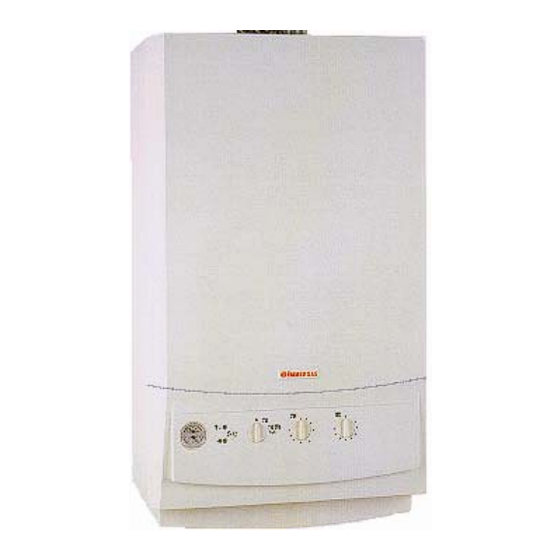
- Page 1 NIKE Mini Export Compact wall-hung instantaneous conventional flue boilers...
- Page 3 Technical documentation Technical documentation NIKE Mini Conventional flue wall-hung boiler with instantaneous production of D.H.W. and compact dimensions NIKE Mini - GENERAL FEATURES NIKE MINI is a wall-hung conventional flue for central heating and the production of domestic hot water that stands out for its compact dimensions (773 x 450 x 250). The boiler features a microprocessor-controlled electronic board that electronically controls burner ignition, central heating and d.h.w.
-
Page 4: Main Component Parts
Technical documentation Technical documentation MAIN COMPONENT PARTS (until serial number 2243650) 1 - Adjustment and limit NTC sensor 8 - Expansion vessel 15- Primary heat exchanger 2 - 3-way hydraulic valve 9 - Combustion chamber 16- Ignition and detection electrodes 3 - Gas valve 10- Automatic air vent valve 17- Burner... -
Page 5: Control Panel
Technical documentation Technical documentation MAIN COMPONENT PARTS (from serial number 2243651) 7 - Adjustment and limit NTC sensor 1 - 3-way hydraulic valve 13- 3-bar safety valve 8 - Expansion vessel 2 - Gas valve 14- System drain valve 9 - Combustion chamber 3 - System filling valve 15- Primary heat exchanger 10- Automatic air vent valve... -
Page 6: Hydraulic Circuit
Technical documentation Technical documentation HYDRAULIC CIRCUIT (until serial number 2243650) 1 - System filling valve 2 - Hot water flow switch micro. 3 - Gas valve 4 - 3-way hydraulic valve 5 - Adjustment and limit NTC sensor 6 - D.h.w exchanger 7 - Burner 8 - Primary heat exchanger 9 - Stack safety thermostat... -
Page 7: Primary Circuit
Technical documentation Technical documentation The hot water used for central heating and the d.h.w. supply is produced by a primary circuit and a secondary circuit (domestic hot water), which operate according to need. PRIMARY CIRCUIT (BOILER CIRCUIT) The primary circuit with relevant control and safety devices is started every time there is a central heating, domestic hot water request or antifreeze request. -
Page 8: Primary Heat Exchanger
Technical documentation Technical documentation - PRIMARY HEAT EXCHANGER This is a blade type water-gas exchanger consisting of four pipes connected together in series. This is connected to pump delivery (return) and to primary circuit delivery (delivery) by means of coupling pipes (3) featuring O.R. seals (5) secured by means of special forks (4). (until serial number2243650) (from serial number 2243651) At the outlet.(delivery) is the overheating safety... - Page 9 Technical documentation Technical documentation - SAFETY DEVICES AND CONTROLS System bypass (1) (optional) Ensures circulation of water in the primary circuit (between delivery and return) even when the high resistance of the system does not permit. It is fitted between the system delivery and return connection pipes.
-
Page 10: Secondary Circuit
Technical documentation Technical documentation HYDRAULIC CIRCUIT SECONDARY CIRCUIT (DOMESTIC HOT WATER CIRCUIT) - OPERATION A d.h.w. request causes cold water to flow through the 3-way valve (1) and its subsequent movement to operating position (see hydraulic 3-way valve operation). This causes the delivery pipe (M) to close with simultaneous opening of the passage towards the d.h.w. exchanger (2). - Page 11 Technical documentation Technical documentation - 3-WAY HYDRAULIC VALVE Whenever a domestic hot water request is made, the 3-way valve has to deviate the flow of water of the primary circuit from the central heating system to the plate exchanger. It is therefore connected to both the primary circuit (primary circuit delivery, system delivery and d.h.w.
- Page 12 Technical documentation Technical documentation Idle position (central heating) The thrust exercised by the spring “1” affects the diaphragm plate “4” and the d.h.w. valve “3” fastened to rod “5”. The valve “2” is thus kept up tight with consequent closing of the passage towards the d.h.w.
-
Page 13: Gas Circuit
Technical documentation Technical documentation GAS CIRCUIT The circuit consists of an atmospheric burner and a modulating type valve for gas combustion and gas flow adjustment respectively. - OPERATION When the main coils (3) are energised, both inner valve shutters open, allowing the gas to flow towards the burner. - Page 14 Technical documentation Technical documentation - BURNER From serial number 1618839 the burner consists of 12 horizontal venturi pipes (6) (ramps were previously 11) in which the gas is injected by an equal number of nozzles (7) mounted on the special collector (8).
-
Page 15: Gas Adjustments
Technical documentation Technical documentation GAS ADJUSTMENTS Max and minimum gas pressure adjustments can be made by means of the gas valve respecting the values shown on the tables relating to each boiler for the type of corresponding gas. After fitting a pressure gauge to the gas valve outlet (see illustration alongside), proceed as follows: - VALVE VK 4105 M (with yellow protection cap) - Page 16 Technical documentation Technical documentation - CHANGING TYPE OF GAS Adaptation to a type of gas different to that for which the boiler is intended, can be done by using the special kits (natural gas or LPG). The changeover consists in replacing the burner nozzles and in moving to the modulation board of the “NATURAL GAS- LPG”...
-
Page 17: Electrical Circuit
Technical documentation Technical documentation ELECTRICAL CIRCUIT E1/E2 - Ignition electrodes - Fault indicator red led - Room thermostat - Detection electrode MOD - Modulation coil - Flue safety device - Fuse - Circulating pump - Overheating safety device - Main switch - Delivery sensor TS2 (*) - Exchanger overheating safety - Gas selector... -
Page 18: Low Voltage Circuit
Technical documentation Technical documentation LOADS This is powered by the adjustment board whenever there is a demand for heating, domestic Circulating pump hot water or antifreeze. (MP) Permits circulation of water in the boiler circuit. This is powered by the ignition circuit of the adjustment board when the burner has to be Gas valve (VG) ignited. - Page 19 Technical documentation Technical documentation By means of the adjustment board, this enables operation of the boiler during heating when room temperature is below that required. Room thermostat (TA) If fitted singly, connection is made to terminals 6 and 9 of connector M3 Double-contact (external optional) after removing the pre-existing jumper P1.
-
Page 20: Heating Phase
Technical documentation Technical documentation ELECTRICAL CIRCUIT HEATING PHASE (*) the main coils of the gas valve run at mains voltage rectified by means of a diode jumper only on the Honeywell VK 4105 gas valve (diode jumper fitted on the valve connection connector) (**) the overheating thermostat TS2 equipped the boiler until the serial number2243650 Operation When the main switch (IG) is in WINTER position, it powers the low-voltage circuit and enables... - Page 21 Technical documentation Technical documentation ELECTRICAL CIRCUIT DOMESTIC HOT WATER PHASE (*) the main coils of the gas valve run at mains voltage rectified by means of a diode jumper only on the Honeywell VK 4105 gas valve (diode jumper fitted on the valve connection connector) (**) the overheating thermostat TS2 equipped the boiler until the serial number 2243650 Operation When main switch (IG) is in SUMMER position, it powers the ignition and modulation board and...
- Page 22 Technical documentation Technical documentation MODULATION BOARD Inside the NIKE MINI control box is a microprocessor-controlled electronic board that, in case of need, can be replaced with that of the EOLO Mini (and not vice versa), without having to make any adjustments or bypass any controls or safety devices.
- Page 23 Technical documentation Technical documentation Subsequently, the signal varies in a way directly proportionate to the difference between the temperature set by means of the heating potentiometer (C.H.) and that read by the NTC heating sensor (NM) and, if necessary, increases so as to reach in 100 seconds the value set by means of the maximum heating output trimmer (C.
- Page 24 Technical documentation Technical documentation INPUTS open = heating Clock programmer This is a clean contact switch controlled by a clock that enables or switch (OP) disables boiler operation in heating phase during selected time closed = heating (optional) intervals This is a resistance that can be varied in a way inversely proportionate to NTC sensor Delivery sensor the temperature of the delivery water of the primary circuit.
-
Page 25: Safety Devices
Technical documentation Technical documentation This is a single-pole relay for controlling the pump (MP). It is excited when operation is PUMP RELAY required. This is a single-pole relay which is excited when the burner has to be ignited. REQUEST RELAY By means of its contact, the adjustment board ignition circuit is controlled. - Page 26 Technical documentation Technical documentation To prevent the water/gas exchanger from overheating, at the end of each heating Pump post- circulation request (opening of room thermostat or antifreeze), the circulator is kept operating for 30 seconds. In the event of the flue thermostat contact being opened (low chimney draught with return of flues into environment) boiler operation is stopped for 30 minutes.
-
Page 27: Flame Detection
Technical documentation Technical documentation NIKE Mini OPERATION SEQUENCE Heating phase Hot water phase POWER SUPPLY POWER SUPPLY Main switch in WINTER position Main switch SUMMER or WINTER position ⇓ ⇓ CLOSING OF ROOM THERM. SWITCH HOT WATER OPERATION REQUEST Room thermostat request Drawing of hot water ⇓... - Page 28 Technical documentation Technical documentation NIKE Mini TECHNICAL DATA Nominal heat input kW (kcal/h) 25.8 (22198) Minimum heat input kW (kcal/h) 10.8 (9324) Nominal heat output (useful) kW (kcal/h) 23.3 (20000) Minimum heat output (useful) kW (kcal/h) 9.3 (8000) Efficiency at 100 % 90.1 Efficiency at 30% (load) Heat loss from casing with burner on / off...
-
Page 29: Combustion Parameters
Technical documentation Technical documentation COMBUSTION PARAMETERS (with combustion air temperature 15 ºc ) Mass flue rate at nominal power kg/h Mass flue rate at minimum power kg/h at nominal power at minimum power CO at 0% of O at nominal power CO at 0% of O at minimum power at 0% of O...