Table of Contents
Advertisement
Quick Links
Technical documentation
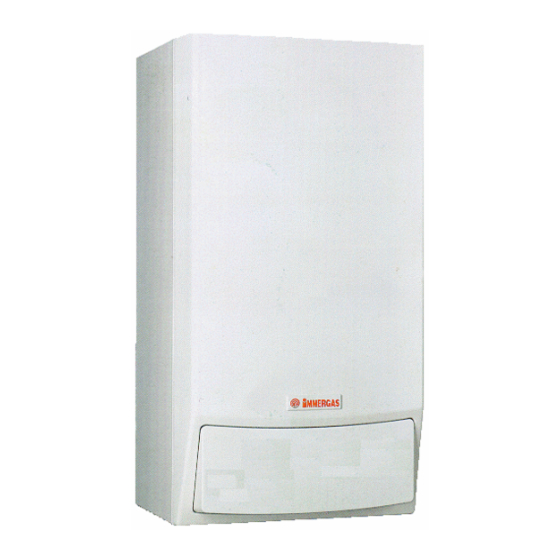
EOLO Superior PLUS
- GENERAL FEATURES
The EOLO Superior Plus is a wall boiler designed to be used together with PLUS storage
tanks ( 80 l, 105 l and 120 l).
Adjustment and control of the two units are entrusted to a microprocessor-controlled
electronic board which, thanks to a display, shows operating conditions (settings,
temperatures, safety devices, etc.).
The boiler has an efficiency over 90% and features a standard anti-frost device which
protects it down to temperatures of -5°C.
The hydraulic circuit features a high-head copper water-gas exchanger, an electric 3-way
valve and an adjustable system by-pass.
Combustion air flow into the sealed chamber and flue extraction are ensured by a fan, the
correct operation of which is controlled by a differential pressure switch.
The appliance is prearranged for the connection to a remote control panel (see Remote
Friend Control technical sheet), to the area control unit (see area control unit technical
sheet) and to the Multisystem Water Disconnector (see D.I.M. technical sheet).
The AISI 316 L STAINLESS STEEL storage tanks feature a standard anode and expansion
vessel and can be connected to the re-circulation system by means of a special kit (optional).
STESP ed 02/02
Wall-hung
combustion chamber and fan-
assisted with external storage tank
EOLO 24 Superior PLUS
1 1
Technical documentation
boiler
with
sealed
EOLO SUPERIOR PLUS
Advertisement
Table of Contents

Related Manuals for Immergas EOLO Superior PLUS 24


Summary of Contents for Immergas EOLO Superior PLUS 24
- Page 1 Technical documentation Technical documentation EOLO Superior PLUS Wall-hung boiler with sealed combustion chamber and fan- assisted with external storage tank EOLO 24 Superior PLUS - GENERAL FEATURES The EOLO Superior Plus is a wall boiler designed to be used together with PLUS storage tanks ( 80 l, 105 l and 120 l).
- Page 2 Technical documentation Technical documentation MAIN DIMENSIONS AND CONNECTIONS BOILER STORAGE TANK UNIT DIMENSIONS (mm) HEIGHT WIDTH DEPTH CONNECTIONS SYSTEM RB-MB RI-MI 1/2 “ 3/4 “ 3/4 “ V - power connection G - gas supply RB - boiler return MB - boiler flow A - system filling RI - system return DIMENSIONS (mm)
-
Page 3: Control Panel
Technical documentation Technical documentation EOLO Superior PLUS MAIN COMPONENTS 1 - Intake points (A=air) (F=fumes) 9 - Sealed chamber 17- 3-way valve 2 - Flue safety pressure switch 10 - Expansion vessel 18- Adjustable automatic by-pass 3 - Fan 11 - Adjustment and limit NTC probe 19- Positive signal pressure point 4–... - Page 4 Technical documentation Technical documentation PLUS STORAGE TANK MAIN COMPONENTS Storage tank 80 l Storage tank 105 l Storage tank 120 l 1 - D.h.w. NTC sensor 4 - D.h.w. expansion vessel 2 - D.h.w. drain valve 5 - Coil 3 - Thermometer 6 - Anode CONTROL PANEL 1 - Storage-tank ON-OFF...
-
Page 5: Hydraulic Circuit
Technical documentation Technical documentation HYDRAULIC CIRCUIT 1 - Gas valve 2 - 3-way valve gearmotor 3 – Electric 3-way valve 4 - Burner 5 - Primary exchanger 6 - Sealed chamber 7 - Draught diverter 8 - Fan fan 9 - Flue safety pressure switch 10- NTC limit and adjust. - Page 6 Technical documentation Technical documentation - CIRCULATOR This operates on the primary circuit return and is located on the brass header assembly. It is connected to the monobloc and exchanger by means of threaded connecting pieces, while the primary exchanger expansion vessel connected by coupling pipes (2) with O.R.
- Page 7 Technical documentation Technical documentation - SAFETY DEVICES AND CONTROLS System bypass (3) This ensures water circulation in the primary circuit (between flow and return) even when this is prevented by the high resistance of the system. It is mounted on a monobloc and can be adjusted by means of a screw accessible from the bottom part of the valve plate.
-
Page 8: Secondary Circuit
Technical documentation Technical documentation HYDRAULIC CIRCUIT - SECONDARY CIRCUIT (D.H.W. CIRCUIT) The domestic hot water circuit is engaged every time the water contained in the storage tank and measured by means of the d.h.w. NTC sensor (4) has to be restored to the desired temperature. - OPERATION Following a d.h.w. - Page 9 Technical documentation Technical documentation - STORAGE TANK UNIT (optional) Re-circulation kit (11) (optional) The PLUS storage tank units ( 80 l, 105 l and 120 Permits connecting the pipes of any d.h.w. re- l) consist of a coil storage tank unit insulated with circulation system.
- Page 10 Technical documentation Technical documentation - MOTORISED 3-WAY VALVE This is a 3-way electric valve operating on the return pipe of the primary circuit that permits, according to the type of request (d.h.w. or central heating), running boiler water into the central heating system or into the storage tank coil.
-
Page 11: Gas Circuit
Technical documentation Technical documentation GAS CIRCUIT - OPERATION (See EOLO Maior @) - MODULATING GAS VALVE (See EOLO Maior @) - BURNER (See EOLO Maior @) GAS ADJUSTMENTS minimum pressure adjustments can be made by means of the gas valve respecting the values shown on the tables relating to each boiler for the type of corresponding gas. - Page 12 Technical documentation Technical documentation - VALVE VK 4105 M-M with integrated flanges (with transparent protection cap) Maximum pressure adjustment - Do a d.h.w.request (open a tap) and setting temperature selector maximum. Turn nut ”3” clockwise to increase pressure to the burner and anticlockwise to decrease pressure Minimum pressure adjustment (operation to be performed after maximum...
- Page 13 Technical documentation Technical documentation FLUE CIRCUIT - OPERATION (See EOLO Maior @) - FAN (See EOLO Maior @) - FLUE PRESSURE SWITCH (See EOLO Maior @) - AIR/FLUE SAMPLING SUMPS (See EOLO Maior @) - FLUE PRESSURE SWITCH SIGNAL PRESSURE POINT (See EOLO Maior @) EXTRACTION AND EXHAUST SYSTEMS (see extraction and exhaust end instructions )
-
Page 14: Electrical Circuit
Technical documentation Technical documentation ELECTRICAL CIRCUIT CAR Remote control Main switch Reset button Control xone unitt MOD Modulation coil Pump pressure switch Central heating operation LED Circulator Flue pressure switch D.h.w. operation LED Room thermostat Flame LED D.h.w. NTC sensor Overheat. - Page 15 Technical documentation Technical documentation LOADS Deviates the flow of water of the primary circuit from the heating circuit to the boiler coil 3-way electric valve and vice versa. (VD) It is powered by the modulation card. Permits circulation of water in the primary circuit. Circulator This is powered by the modulation board whenever there is a demand for d.h.w., (MP)
- Page 16 Technical documentation Technical documentation This acts on the modulation board and permits interrupting power to Double-contact Pump pressure switch the control unit in the event of there being no circulation in the boiler switch (SP) circuit. Permits remote control of boiler (iSUM/WINT switch, temperature See Remote adjustment and indication, alarm display, reset, etc.) and acts as a Remote control (CAR)
- Page 17 Technical documentation Technical documentation ELECTRICAL CIRCUIT CENTRAL-HEATING PHASE (*) only on the Honeywell VK 4105 gas valve, the main coils are powered at mains voltage by means of a diode bridge (fitted in the connection connector) When the mainr switch (IG) is in WINTER position, it powers the modulation card and enables operation in central heating mode.
- Page 18 Technical documentation Technical documentation ELECTRICAL CIRCUIT D.H.W. PHASE (*)only on the Honeywell VK 4105 gas valve, the main coils are powered at mains voltage by means of a diode bridge (fitted in the connection connector) Operation When the main switch (IG) is in SUMMER or WINTER position, it powers the modulation board and enables operation in d.h.w.
- Page 19 Technical documentation Technical documentation MODULATION CARD The boiler is equipped with a microprocessor-controlled electronic board used on both the models with 3-way electric valve (Zeus Superior, Eolo Superior Plus) and on the models with central-heating and d.h.w. pumps (Hercules). The different type of operation is obtained by adjusting diode D9 (diode engaged = electric 3-way valve, diode disengaged = double pump).
- Page 20 Technical documentation Technical documentation The circulation of the water causes the pump pressure switch (SP) to close and because this is connected in series to the NC contact of the flue pressure switch (SV) powers the coil of relay “K5”. If the temperature detected by means of NTC central-heating sensor (NR) is below that set by means of the central heating potentiometer of the remote control (CAR), the adjustment circuit excites relay “K5”...
- Page 21 Technical documentation Technical documentation INPUTS This is a resistance that varies in a way inversely proportionate to the Sensor NTC Central-heating sensor temperature of the water flow in the primary circuit. 10 kohm 25 ºC (NR) It is used as a limit thermostat (90 ºC). Sensor NTC D.h.w.
- Page 22 Technical documentation Technical documentation OUTPUTS This relay permits powering the motor of the 3-way electric valve (VD). 3-way valve relay (R3V) It is excited by a central-heating request and remains idle with a d.h.w. request. This signal enables the control zone unit to know the operating condition of the Control zone unit (CZ) appliance (d.h.w./heating) and, if fitted, to recognise the CAR as area 1 room (optional )
-
Page 23: Safety Devices
Technical documentation Technical documentation ADJUSTMENTS C.-heating potentiometer Permits setting the temperature of the water for central-heating use between 38ºC (HEATING) and 85 ºC. At each switch-off due to temperature being reached during Central-heating timing absent = 30 s central-heating, a delay is engaged of 3 min / 30 s until the next present = 3 min (J1) re-ignition for the same type of request. - Page 24 Technical documentation Technical documentation INDICATORS (display board) This green LED lights up when the boiler is working in central-heating and antifreeze mode. This green LED lights up when the boiler is working in d.h.w. mode. This orange LED lights up when the burner is operating. Depending on the condition, this indicates: - the value of the temperature detected by the delivery sensor (NR) during operation in central-heating, d.h.w., antifreeze and chimneysweep mode.
- Page 25 Technical documentation Technical documentation EOLO Superior PLUS OPERATION SEQUENCE Central-heating phase D.h.w. phase STARTING STARTING Main switch in WINTER position Main switch in SUMMER or WINTER position ⇓ ⇓ ⇓ ⇓ MODULATION CARD AND CAR (remote MODULATION CARD AND CAR (remote control) POWER SUPPLY control) POWER SUPPLY When the main switch contacts close (WINTER position)
- Page 26 Technical documentation Technical documentation EOLO 24 SUPERIOR PLUS TECHNICAL DATA Nominal heat input kW (Kcal/h) 30.0 (25834) Minimum heat input kW (Kcal/h) 12.2 (10466) Nominal heat output (useful) kW (Kcal/h) 27.9 (24000) Minimum heat output (useful) kW (Kcal/h) 10.5 (9000) Useful heat efficiency at rated power 92.9 Useful heat efficiency at 30% load at nominal output...
-
Page 27: Combustion Parameters
Technical documentation Technical documentation COMBUSTION PARAMETERS (with combustion air temperature 15 ºC) Nominal output fume mass flow kg/h Minimum output fume mass flow kg/h at nominal output at minimum output CO at 0% of O at nominal output CO at 0% of O at minimum output at 0% of O at nominal output...