
Related Manuals for Samsung CE115KSR


Summary of Contents for Samsung CE115KSR
-
Page 1: Table Of Contents
MICROWAVE OVEN CE115KSR SERVICE Manual MICROWAVE OVEN CONTENTS 1. Precaution 2. Specifications 3. Operating Instructions 4. Disassembly and Reassembly 5. Alignment and Adjustments 6. Troubleshooting 7. Exploded Views and Parts List 8. PCB Diagrams 9. Schematic Diagrams... - Page 2 ELECTRONICS © Samsung Electronics Co., Ltd. March 2004 This Service Manual is a property of Samsung Electronics Co.,Ltd. Any unauthorized use of Manual can be punished under applicable Printed in Korea International and/or domestic law Code No. : DE68-03425A...
- Page 3 PRECAUTIONS TO BE OBSERVED BEFORE AND DURING SERVICING TO AVOID POSSIBLE EXPOSURE TO EXCESSIVE MICROWAVE ENERGY (a) Do not operate or allow the oven to be (c) Before turning on microwave power operated with the door open. for any service test or inspection within (b) Make the following safety checks on the microwave generating all ovens to be serviced before activating...
-
Page 4: Precaution
1. Precaution Follow these special safety precautions. Although the microwave oven is completely safe during ordinary use, repair work can be extremely hazardous due to possible exposure to microwave radiation, as well as potentially lethal high voltages and currents. 1-1 Safety precautions ( 11. - Page 5 1-2 Special Servicing Precautions (Continued) 17. When checking the continuity of the witches or transformer, always make sure that the power is OFF, and one of the lead wires is disconnected. 18. Components that are critical for safety are indicated in the circuit diagram by shading, or .
-
Page 6: Specifications
2. Specifications 2-1 Table of Specifications TIMER 99 MINUTES POWER SOURCE 230V 50Hz, AC POWER CONSUMPTION MICROWAVE : 1,500W OUTPUT POWER 900W(10 LEVER POWER) (IEC-705 TEST PROCEDURE) OPERATING FREQUENCY 2,450MHz MAGNETRON OM75PH(31) COOLING METHOD COOLING FAN MOTOR OUTSIDE DIMENSIONS 547(W) x 339(H) x 528(D)mm NET WEIGHT 26.0 kg SHIPPING WEIGHT... -
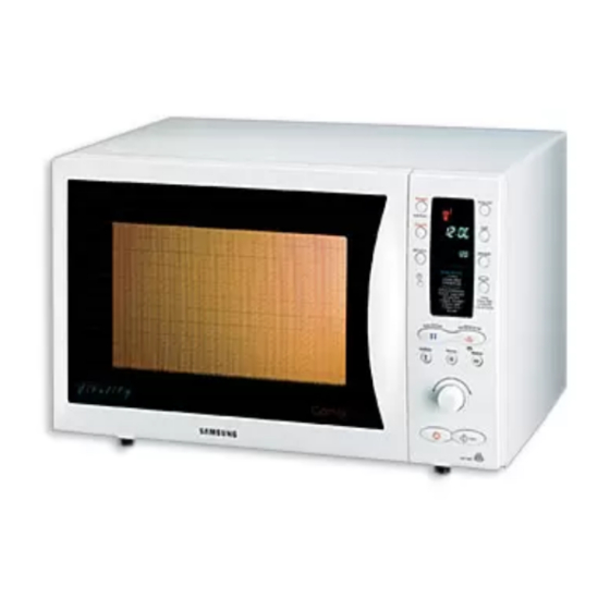
Page 7: Operating Instructions
3. Operating Instructions 3-1 Control Panel 3-2 Features & External Views Ventilation Slot Light Door Safety Interlock Holes Control Pane Guide Roller Glass Plate Door Latches 225mm 547mm 528mm - 4 -... -
Page 8: Disassembly And Reassembly
4. Disassembly and Reassembly 4-1 Replacement of Magnetron, Motor Assembly and Lamp Remove the magnetron including the shield case, permanent magnet, choke coils and capacitors (all of which are contained in one assembly). 1. Disconnect all lead wires from the magnetron and lamp. - Page 9 4-3 Replacement of Door Assembly 4-3-1 Removal of Door Assembly 4-3-4 Removal of Key Door &Spring Remove pin hinge from Door "E" Remove screws securing the upper hinge and Detach spring from Door "E" and key door. lower hinge. Then remove the door assembly 4-3-2 Removal of Door "C"...
- Page 10 4-3-6 Reassembly Test After replacement of defective component parts of the door, reassemble it and follow the instructions below for proper installation and adjustment so as to prevent an excessive microwave leakage. 1. When mounting the door to the oven, be sure to adjust the door parallel to the bottom line of the oven face plate by moving the upper hinge and lower hinge in the direction necessary for proper alignment.
- Page 11 4-6 Replacement of Control Circuit Board 4-6-1 Removal of Control Box 1. Be sure to disclyarge any static electricity from your body, and avoid touching the " Touch control" circuitry. 2. Disconnect the connectors from the control circuit board. 3. Remove screws securing the control circuit board. 4.
-
Page 12: Troubleshooting
6. Troubleshooting PRECAUTION 1. CHECK GROUNDING BEFORE CHECKING FOR TROUBLE. 2. BE CAREFUL OF THE HIGH VOLTAGE CIRCUIT. 3. DISCHARGE THE HIGH VOLTAGE CAPACITOR. 4. WHEN CHECKING THE CONTINUITY OF THE SWITCHES OR TRANSFORMER, DISCONNECT ONE LEAD WIRE FROM THESE PARTS AND THEN CHECK CONTINUITY WITHOUT THE POWER SOURCE ON. - Page 13 6-1 Electrical Malfunction(continued) SYMPTOM CAUSE CORRECTIONS Oven lamp and fan motor turn on 1. Misadjustment or loose wiring Adjust door and latch switches. of primary latch switch 2. Defective primary latch switch Oven can program but timer 1. Open or loose wiring of does not start.
-
Page 14: Exploded Views And Parts List
7. Exploded Views and Parts List 7-1 Exploded Views M001 M002 P186 M003 W006 W021 W003 M005 M013 M113 M058 M095 M054 M008 M010 M015 M011 M053 H008 M019 M031 M017 M012 M116 M063 M020 W002 M004 M029 M114 M036 M025 M051 D048... - Page 15 7-2 Main Parts List Code No. Description Specification Q'ty Remark B001 3405-001034 SWITCH-MICRO 125/250VAC,16A,200GF,SPST-N B002 3405-001032 SWITCH-MICRO 125/250VAC,16A,200GF,SPDT B006 DE66-40021A LATCH-BODY -,-,-,RE-330,-,-,- B009 DE66-90054A LEVER-SWITCH POM(F20-02),15G,NTR,RE-330, B018 DE93-20020A ASSY BODY LATCH RE-43B/90B,-,-,-,- D048 DE63-90062A CUSHION-RUBBER DOOR -,RUBBER(CR),T9,W30, H008 DE60-40026B WASHER-PLAIN ID5.5,OD12,T1.0,SBC1,ZNC3,- M001 DE70-30120K...
- Page 16 7-2 Main Parts List Code No. Description Specification Q'ty Remark M040 DE61-50106A BRACKET-HVC -,SECC,T0.8,W31,L125.8,-,- M041 DE59-00002A DIODE-H.V ESJC13-12B,12KV,-,-,-,MWO ALL, M042 DE91-70061A ASSY-H.V.FUSE THV060T-0800-H,5KV/0.80A,W M044 DE26-20152A TRANS L.V SLV-105E,230V,50HZ,AC17V/3V,-, M046 DE60-60025A PIN-FOOT PP-JI350,BLK,-,-,-,-,-,- M047 DE61-40026A FOOT -,PP-JI350,-,BLK,-,-,- M048 DE80-10115A BASE-PLATE -,SGCC1-Z,T0.8,W544,L345.5,CE M049 DE31-10170A MOTOR SYNCHRONOUS...
- Page 17 MB245,Y745STC,S7A77,T3.0,W26 D010 DE61-80006B HINGE-LOWER -,SHV-745CC1,SSEC,T3.0,ZN(PL D011 DE64-40175A DOOR-KEY -,POM(TC3005),RE-330,-,-,-,13G, D016 DE64-40286A DOOR-SUB 100G,PC,L402.6,-,-,-,W267.6,- D017 DE60-60008F PIN-HINGE PI4,L15,NYLON#66,CE115K,BLK,-, D019 DE64-20117C HANDLE-DOOR CE119KFS/XEF,PC,-,-,-,-,SIL, D024 DE67-20163L SCREEN-DOOR(B) SILVER,CE115KSR/BWT,-,-,- D049 ASSY DOOR CE115KSR/BWT,SILVER,BIO MARK P S.N.A S.N.A : SERVICE NOT AVAILABLE - 18 -...
- Page 18 C035 C043 C045 C012 C041 C082 Code No. Description Specification Q'ty Remark C003 RCS-115K-01 ASSY PCB PARTS CE115K,230V50HZ C005 DE72-00097B CONTROL-PANEL CE115KSR/BWT,PC,-,-,-,-,SI C009 DE67-40150F WINDOW-DISPLAY -,ACRYL,SMG,30G,CE118KFR( C011 DE66-20192C BUTTON-SELECT(A) CE119KFS/XEF,-,-,-,-,- C012 DE66-20196C BUTTON-SELECT(B) CE119KFS/XEF,-,-,-,-,- C025 DE64-10132D KNOB CE119KFS/XEF,PC,-,-,-,-,SIL,COATING C035 DE66-20195C...
- Page 19 7-5 Casing Parts List H001 H012 H013 H003 H011 H004 H002 H005 H002 H006 H024 H007 H008 H016 Code No. Description Specification Q'ty Remark H001 DE31-10171A MOTOR CONVECTION SMC-105EA,230V/50HZ,280 H002 DE31-90019A BLADE-FAN SECC,T0.6,-,-,-,-,- H002 DE31-90020A BLADE-FAN ALSTAR,T0.6,W250,L250,-,-,- H003 DE47-70077A HEATER-CONVECTION SHC-118E1,-,-,1680W,-, H004 DE61-50484A...
- Page 20 7-6 Standard Parts List Code No. Description Specification Q'ty Remark DE60-20014A BOLT-FLANGE M5,L10,MSWR3,FEFZY,-,-,-,-,- HINGE DE60-30016A NUT-FLANGE M4,MSWR10,-,-,-,-,-,-,- SENSOR DE60-30016B NUT-FLANGE M4,MSWR10,FEFN,-,-,-,-,-,- 6006-001171 SCREW-ASSY MACH WS,PH,+,M4,L8,NI PLT B/EART 6006-001170 SCREW-ASSY TAPP WS,TH,+,M4,L10,ZPC(YEL) CH-PCB 6006-001170 SCREW-ASSY TAPP WS,TH,+,M4,L10,ZPC(YEL) P-C-EA 6006-001170 SCREW-ASSY TAPP WS,TH,+,M4,L10,ZPC(YEL) PCB-EA 6006-001174...
- Page 21 8-2 P.C.B Parts List Code No. Description Specification Q'ty Remark DE30-20016A BUZZER CBE2220BA,STICK,-,-,-,-,-,-,- BUZ1 2401-000244 C-AL 100uF,20%,10V,GP,TP,6.3x7,5 C03,C15 2401-000360 C-AL 100uF,20%,50V,GP,TP,8x11.5,5 2401-000466 C-AL 10uF,20%,35V,GP,TP,5x7,5 2401-000598 C-AL 1uF,20%,50V,GP,TP,4x7,5 2401-000911 C-AL 22uF,20%,16V,GP,TP,5x7,5 2401-001415 C-AL 470uF,20%,35V,GP,TP,10x20,5 2401-002075 C-AL 4.7uF,20%,50V,GP,TP,5x11,5 2202-000205 C-CERAMIC,MLC-AXIAL 22pF,5%,50V,SL,TP,1.9x3.5,- C11,C12 2202-002037 C-CERAMIC,MLC-AXIAL 100nF,80-20%,50V,Y5V,TP,2.2x3.
-
Page 22: Schematic Diagrams
9. Schematic Diagrams 9-1 Schematic Diagrams ( This Document can not be used without Samsung's authorization ) ASSY CHOCK P.C.B CAVITY PRIMARY T.C.O T.C.O SWITCH H.V.T H.V.D 230V~ 50Hz H.V.C MONITER SWITCH H.V.FUSE (0.8A) Thermistor Sensor RESISTOR INRUSH MAIN RELAY...