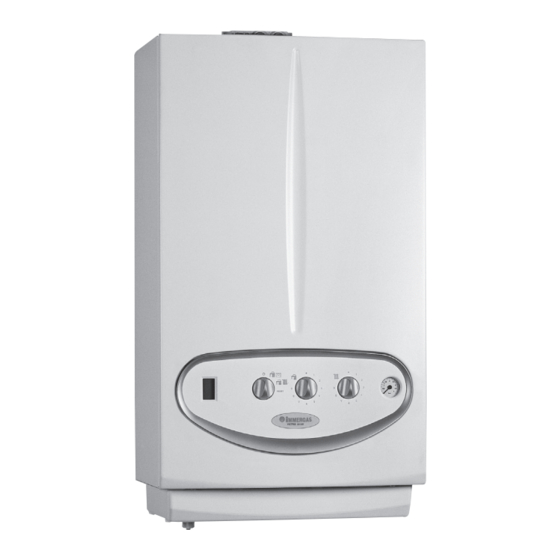
Immergas VICTRIX 26 2 I Manual
Condensation-type wall-hung boiler
Hide thumbs
Also See for VICTRIX 26 2 I:
- Instruction booklet and warning (28 pages) ,
- Manual (23 pages) ,
- Instruction booklet and warning (36 pages)

Related Manuals for Immergas VICTRIX 26 2 I


Summary of Contents for Immergas VICTRIX 26 2 I
- Page 1 VICTRIX 26 2 I Instant wall-hung boilers condensation-type VICTRIX X12 2 I - X 24 2 I Condensation-type wall-hung boiler for central heating only or with an external storage tank...
-
Page 3: General Features
VICTRIX 26 2 I General features. VICTRIX 26 2 I is a wall-hung sealed instant boiler (type C) exchanger) the hydraulic circuit is also made up from the with useful heat output of 23.6 kW (20,296 kcal/h) in central hydraulic unit in composite material. - Page 4 Ø 80 mm rigid and Ø 80 mm flexible) realised in plastic and Adjustment and control of the appliance are entrusted to designed expressly for Immergas condensing boilers. a P.C.B. with micro processor with continuous flame mo- dulation, which using a back-lit display shows the boiler functioning status (temperatures, safety devices, etc.)and allows...
- Page 5 Ø 80 mm rigid and Ø 80 mm flexible) realised in plastic and Adjustment and control of the appliance are entrusted to a designed expressly for Immergas condensing boilers. P.C.B. with micro processor with continuous flame modu- lation, which using a back-lit display shows the boiler fun- ctioning status (temperatures, safety devices, etc.) and allows...
- Page 6 Technical Documentation Technical Documentation VICTRIX 26 2 I main components and connections. Height (mm) Width (mm) Depth (mm) CONNECTIONS DOMESTIC SYSTEM HOT WATER 3/4” 1/2” 1/2” 3/4” 3/4” Key: V - Electric connection G - Gas supply AC - Domestic hot water outlet AF - Domestic hot water inlet SC - Condensate drain (minimum internal diameter Ø...
- Page 7 Technical Documentation Technical Documentation VICTRIX X 12 2 I main components and connections. Height (mm) Width (mm) Depth (mm) CONNECTIONS DOMESTIC SYSTEM 3/4” 1/2” 3/4” 3/4” Key: V - Electric connection G - Gas supply RU - Cylinder unit return (optional) MU - Cylinder unit flow (optional) RR - System filling SC - Condensate drain (minimum internal diameter Ø...
- Page 8 Technical Documentation Technical Documentation VICTRIX 2 I control panel. Key: 1 - Boiler status signal display 2 - Stand-by-Domestic water / Remote Control - Domestic water and Heating-Reset Selector switch 3 - Domestic hot water temperature selector switch 4 - Central heating temperature selector switch 5 - Boiler manometer STV2I ed 11/09 VICTRIX 2 I Export...
- Page 9 Technical Documentation Technical Documentation VICTRIX 26 2 I main components. Key: 1 - Electric connection terminal board (very low voltage) 2 - Condensate drain trap 19 - Positive signal pressure point 3 - D.h.w. heat exchanger 20 - Igniter 4 - Gas valve...
- Page 10 Technical Documentation Technical Documentation VICTRIX X 12 2 I - X 24 2 I main components. Key: 1 - Electric connection terminal board 17 - Manual air vent valve (very low voltage) 18 - Negative signal pressure point 2 - System draining valve 19 - Positive signal pressure point 3 - Gas valve 20 - Sample points (air A) - (flue F)
- Page 11 Technical Documentation Technical Documentation VICTRIX 26 2 I hydraulic diagram. Key: 1 - Condensate drain trap 2 - Domestic hot water flow switch 3 - Flow limiter 4 - System filling valve 5 - Domestic hot water probe 6 - Gas valve...
- Page 12 Technical Documentation Technical Documentation VICTRIX X 12 2 I - X 24 2 I hydraulic diagram. Key: 1 - Condensate drain trap 2 - System filling valve 3 - Gas valve 4 - Gas valve outlet pressure point (P3) 5 - Venturi positive sign (P2) 6 - Venturi negative sign (P2) 7 - Air/gas Venturi manifold 8 - Fan...
- Page 13 The water is introduced directly into the system or can be diverted inside the stainless steel instant plate heat exchanger (32). VICTRIX 26 2 I - VICTRIX X 24 2 I Flow rate Litres/h VICTRIX X 12 2 I Flow rate Litres/h...
-
Page 14: Boiler Pump
(see flue circuit). VICTRIX 26 2 I and VICTRIX X 24 2 I: The first three elements are affected directly by the action of the cylindrical burner applied to the front, while the fourth is arranged in the condensation chamber, which is separated from the combustion chamber by sheet steel (see flue circuit). - Page 15 Technical Documentation Technical Documentation Motorised three-way valve for instant versions only. It is made up from a small electric motor (1) connected, by Heat exchanger means of a relevant clip, to the 3-way valve group (2). Flow According to the request (DHW or CH), the 3-way valve allows to introduce boiler water into the central heating system or Heat exchanger Return...
- Page 16 Technical Documentation Technical Documentation Safety devices and controls for instant versions. System automatic by-pass (4). Guarantees the circulation of water in the primary circuit (between flow and return) also when the high resistance of the system does not allow it. It is mounted between the pump body and the 3-way valve group.
- Page 17 Technical Documentation Technical Documentation Small motor for 3-way valve (optional) for cen- tral heating versions only. A small electric motor (1) connected to the 3-way valve group (2) and blocked using a relevant clip that allows, according Heat exchanger to request (DHW or CH), to introduce the boiler water Return into the heating system or into the domestic hot water heat exchanger(Separate 80, 105, 120 and 200 litre storage tank...
- Page 18 Technical Documentation Technical Documentation Safety devices and controls for central heating only versions. System automatic by-pass (4). Guarantees the circulation of water in the primary circuit (between flow and return) also when the high resistance of the system does not allow it. It is mounted between the pump body and the 3-way valve group.
-
Page 19: Operation
Technical Documentation Technical Documentation Secondary circuit (Domestic Hot water Circuit) for instant versions. Operation. A DHW withdrawal leads to the passage of cold water inside the DHW flow switch (1) and the consequent closure of the electric contact coupled to it (see electric circuit). Following this, the integrated P.C.B. -
Page 20: Dhw Heat Exchanger
Technical Documentation Technical Documentation Domestic hot water flow switch (2). With respect to a withdrawal of DHW with a flow rate of at least 1.5 l/min and a dynamic pressure of 0.3 bar, the flow switch (2) enables the boiler functioning in DHW mode. This takes place by means of a magnet which, lifting when it is hit by the flow of domestic cold water, approaches an electric contact (reed relay) and causes shifting due to the... -
Page 21: Gas Valve
Technical Documentation Technical Documentation Air-gas circuit. The calibration of the ratio between the air and gas pressures are carried out on the valve (off-set) (see gas regulations). Electric coils (4). There are two ON-OFF coils that are powered (230 V AC) by the integrated P.C.B. - Page 22 Technical Documentation Technical Documentation Fan. Operates upstream from the combustion chamber and is positioned under the condensation module. It is controlled by the integrated P.C.B. with a positive square wave signal with variable ON-OFF (duty-cycle) ratio. Its speed is adjusted (from about 1000 to about 5500 rpm) depending on the power requested and is controlled using a sensor with Hall effect, which detects the number of revs.
-
Page 23: Ignition Electrodes
Technical Documentation Technical Documentation Ignition electrodes (7). They are controlled by an igniter (activated by the integrated P.C.B.) that causes an electrical spark between the two electro- des on which, on contact, the air-gas mixture ignites. The electrode (8) has no ceramic insulation and is connected directly to earth (blind electrode). - Page 24 Technical Documentation Technical Documentation Disassembly of combustion circuit main components. Before disassembling the components, make sure the gas cock including the flue hood from the flange with sample points. is closed. Loosen the four screws (6) that fix the condensation module (7) to the support sheet steel (4), which are fixed using the screws Gas nozzle replacement (17).
- Page 25 Technical Documentation Technical Documentation Air-gas adjustments. The calibration of the total premix combustion system, when water adjustment selector switch on notch N° 6 and the necessary envisions the adjustment of the nominal heat output central heating adjustment selector switch on notch N° 9. and the air-gas ratio (off-set).
- Page 26 Domestic hot water Central heating central heating and domestic VICTRIX 26 2 I - X 24 2 I position on hot water minimum speed notch 5 adjustment...
-
Page 27: Gas Transformation
Technical Documentation Technical Documentation To carry out the control correctly and, if necessary, regulate By turning in a clockwise direction the CO value decreases, the air-gas ratio, proceed as follows: by turning in an anti-clockwise direction, it increases. VK 4115 gas valve Gas transformation. -
Page 28: Condensate Drain Trap
Technical Documentation Technical Documentation Flue circuit. Flue exhaust Condensate Drain Operation. The functioning of the fan positioned at the entry of the air- gas mixing pipe, guarantees the fan-assisted expulsion of the combustion products (5). These directly hit the first two elements (version 12 2 I) or three elements (version 26 2 I) of the primary heat exchanger inserted in the sealed combustion chamber (6), which has a sheet steel section on its base (7) that divides it from the... - Page 29 The generators with condensation technology must be installed using the specific series of intake and exhaust pipes, which have been designed to be coupled exclusively to the Immergas condensing boiler. ment, making use of the free space between the lower part of The “GREEN SERIES”...
- Page 30 Technical Documentation Technical Documentation ter of 80 in an individual flue or directly to the outside. 60/100 push-fitting horizontal concentric kit. The exhaust pipe in PPS (Ø 60 mm) is inserted inside the aluminium exhaust pipe (Ø 100 mm). Configuration with sealed chamber and fan- Connection to the boiler takes place using a 90º...
- Page 31 Connections to the boiler take place using the two appropriate Immergas condensing appliance. flanges that allow exhaust (4) from the central fitting and Fit a 90° bend (5) to the appliance exhaust pipe which, using...
- Page 32 It is a kit that allows ducting Ø 80 mm of existing flues/ chimneys/technical slots to be used exclusively with a unique chimneys/technical slots to be used exclusively with a unique Immergas condensing appliance. Immergas condensing appliance. Fit a 90° bend (5) to the appliance exhaust pipe which, using Fit an 87°...
-
Page 33: Electric Circuit
- Room thermostat jumper - Boiler pump - Gas valve The electric circuit of the VICTRIX 26 2 I is completely in- The control and safety devices partly operate at network voltage terlocked to a P.C.B. with integrated microprocessor, which (230 V AC) and partly at low voltage. - Page 34 Technical Documentation Technical Documentation Cuts the power supply to the circuit transformer off (230V/24V) Transformer fuse 315 mAT 250 V in low voltage when the current absorbed exceeds 315mA. It is 230V / 24V delayed fuse (F2) inserted onto the integrated P.C.B. When the flue safety temperature is exceeded (115 °C) remove the Flue safety thermofuse power supply to the main coils of the gas valve.
-
Page 35: Low Voltage Circuit
Technical Documentation Technical Documentation Low voltage circuit. Safety devices and controls. Allows long distance control of the generator (SUM/WIN selector Comando Amico Remoto See Comando Ami- switch, temperature adjustment and indication, alarms display, reset, remote control co Remoto remote etc.) and acts as weekly timer thermostat. (CAR) control functio- If the CAR is installed the pre-existing X40 jumper must be eli-... -
Page 36: Display Board
Technical Documentation Technical Documentation Enables functioning in CH mode when the room temperature is Room thermostat (S20) below that requested. Contact in (external optional) If the CAR is installed, the room thermostat must be disconnected Shut-off without restoring the pre-existing jumper X40. Loads. - Page 37 Technical Documentation Technical Documentation Electric circuit. CH mode. SAFETY EXTRA LOW VOLTAGE CIRCUIT WINTER ONE RELAY BOARD ZONES CONTROL (OPTIONAL) UNIT (OPTIONAL) ONE RELAY BOARD (OPTIONAL) FAN SPEED Operating with room thermostat. Operating with Comando Amico Remoto remote The main switch (S2) in “WINTER" position enables fun- control.
-
Page 38: Dhw Mode
Technical Documentation Technical Documentation Electric circuit. DHW mode. SAFETY EXTRA LOW VOLTAGE CIRCUIT WINTER ONE RELAY BOARD ZONES CONTROL (OPTIONAL) UNIT (OPTIONAL) ONE RELAY BOARD (OPTIONAL) FAN SPEED Operation. The main switch (S2) in “SUMMER or WINTER" position enables functioning in the DHW mode. A withdrawal of DHW causes the contact to close (S4). - Page 39 (E14), exchanger safety thermofuse (E13) and the overheating thermostat (E4), power both the tank or instant (VICTRIX X 24 2 I, VICTRIX 26 2 I) is the same. The different type of boiler functioning is recognised coils of the gas valve (Y1).
- Page 40 Technical Documentation Technical Documentation temperature selector switch and the temperature detected by the DHW probe (B2). DHW request for instant boilers. When the temperature measured by the DHW probe (B2) ex- Following closure of the DHW flow switch (S4) the burner ceeds the value requested (set temperature), the K1 and K3 relay ignites in the same way as the central heating mode.
- Page 41 Technical Documentation Technical Documentation N.B.: If the main switch is held (S2) in the Reset position for a time exceeding 15 seconds, the "chimney sweep" function is exited and the calibration function is activated (see heat output adjustment). If the main switch is turned (S2) for more than 30 seconds, the boiler will go to the Stand-by status and the error code E08 will be displayed, equivalent to "Reset selector switch fault".
- Page 42 Technical Documentation Technical Documentation Inputs. Comando Amico Remoto It sends SUMMER/WINTER selector switch, DHW and CH temperature adjustment (CAR) (optional) and CH request signals to the board (time, room temperature, error codes, etc...). (see CAR functioning) Indicates that a DHW request is in progress. Domestic hot water flow switch (S4) Following withdrawal of DHW it enables boiler functioning in the...
- Page 43 Technical Documentation Technical Documentation It is a square wave signal detected with a Hall effect sensor inserted into the fan. It allows Fan speed the board to measure the speed and correct it if it does not comply with the requested value.
-
Page 44: Safety Devices
Technical Documentation Technical Documentation Adjustments. Absent = With the SUM/WIN selector switch in the WINTER position, it Pump mode selector switch Continuous func. allows the pump to function continuously or only on request of (S10) Present = the room thermostat. RT request func. - Page 45 Technical Documentation Technical Documentation In the case of dispersion of the detection circuit or anomaly in the flame control that generates a correct ionisation current (without the gas valve being open) with the duration Parasite flame block of at least 20 seconds, boiler functioning is blocked. The main switch (S2) must be turned to the Reset position in order to restore functioning of the appliance.
- Page 46 Technical Documentation Technical Documentation Sealed chamber post-ven- The combustion chamber is washed after switch-off of the burner at the end of any request tilation and the fan works for 55 seconds at minimum set speed. Sealed chamber post- After burner switch-off following an overheating block (water or combustion products), the ventilation following fan is made to work for 600 seconds (10 min) at maximum set speed in order to dispose overheating safety block...
-
Page 47: Fault And Anomaly Signals
Technical Documentation Technical Documentation Fault and anomaly signals. The VICTRIX 2 I boiler signals the functioning status of the appliance by symbols on the digital display and any anomaly by the flashing relative error code. Key of control panel display symbols Description Symbol Numerical characters to indicate temperatu-... - Page 48 Technical Documentation Technical Documentation Code Functioning anomaly signalled Remote display Flashing No ignition block Safety thermostat block (overheating), flue thermostat or flame control anomaly NTC flow probe anomaly Domestic hot water NTC probe anomaly (for instant boilers) Reset selector switch fault Calibration function active (displayed only on CAR) No circulation Storage tank probe anomaly (for boilers with storage tank)
-
Page 49: Technical Data
Technical Documentation Technical Documentation Technical Data. VICTRIX 26 2 I technical data. Domestic hot water nominal heat input kW (kcal/h) 26.7 (22933) Central heating nominal heat input kW (kcal/h) 24.1 (20747) Minimum heat input kW (kcal/h) 3.2 (2719) Domestic hot water nominal heat output (useful) kW (kcal/h) 26.0 (22360) - Page 50 Total head available with 1000/h flow rate kPa (m H 8.24 (0.84) *Specific capacity “D” UB Immergas 80 l (∆T 30°C) according to EN 625 l/min 17.2 *Specific capacity “D” UB Immergas 105 l (∆T 30°C) according to EN 625 l/min 21.0...
- Page 51 Total head available with 1000/h flow rate kPa (m H 18.63 (1.90) *Specific capacity “D” UB Immergas 80 l (∆T 30°C) according to EN 625 l/min 20.5 *Specific capacity “D” UB Immergas 105 l (∆T 30°C) according to EN 625 l/min 24.8...
- Page 52 64 / 21 250 / 29 66 / 11 Flue temperature at nominal output °C Flue temperature at minimum output °C VICTRIX 26 2 I / X 24 2 I variable heat output. METHANE (G20) BUTANE (G30) PROPANE (G31) HEAT HEAT BURNER PRESS.
- Page 53 Technical Documentation Technical Documentation VICTRIX X 12 2 I combustion parameters. Supply pressure mbar (mm H 20 (204) 29 (296) 37 (377) Gas nozzle diameter 3.70 2.80 2.80 Flue flow rate at max heat output kg/h Flue flow rate at min heat output kg/h at Q.
- Page 54 Technical Documentation Technical Documentation List of VICTRIX 26 2 I accessories and optionals. Super Comando Amico Remoto remote control Comando Amico Remoto remote control code 3.016577 code 3.011236 Telephone control External Probe code 3.013305 code 3.014083 Digital weekly timer-thermostat Radio timer-thermostat (wireless) code 3.014438...
- Page 55 Technical Documentation Technical Documentation List of VICTRIX X 24 2 I - X 12 2 I accessories and optionals. Super Comando Amico Remoto remote control Comando Amico Remoto remote control code 3.016577 code 3.011236 Zones control unit kit External Probe code 3.011668 code 3.014083 Digital weekly timer-thermostat...
-
Page 56: Ignition Cycle
Technical Documentation Technical Documentation VICTRIX 26 2 I troubleshooting. Before every intervention: Check that the gas, water and electricity are correctly connected nents, remove the electric power supply upstream from the to the boiler, according to that indicated in the data plate and appliance. - Page 57 Technical Documentation Technical Documentation The burner stays on after the first The error 01 appears on the display See error section 01 -c 10 seconds. (wait for the board to make 2 ignition cycles). The error 02 appears on the display See error section 02 - b The error 27 appears on the display See error section 27...
-
Page 58: Functioning Anomalies
Technical Documentation Technical Documentation Functioning anomalies. ERROR 01 No ignition block 230 VAC are present on clamps 2-3 of connector X7. Replace the P.C.B. 230 VAC are present at the ends of the igniter. Replace wiring. The cables between igniter and electrodes corresponds. Restore the electric connection/replace the wiring. - Page 59 Technical Documentation Technical Documentation The pump functions correctly. See section B N.B.: make sure that the pump functions at maximum speed. Restore circulation in the CH system by acting on the closed devices and also check: Any CH system zone valve or cut-off cocks are open. - the correct functioning of the boiler by-pass;...
- Page 60 Technical Documentation Technical Documentation Wiring configuration error N.B.: This board can be used for instant type boilers (VICTRIX 26 2 I) or with ERROR 15 storage tank (VICTRIX X 12 - X 24 2 I). The board automatically recognises the type of boiler by means of the relative wiring.
- Page 61 The Remote Control is connected correctly. The remote control connection must be made using a dedicated line in N.B.: it is possible to use only remote controls supplied by Immergas. order to prevent interference. Replace the remote control. If the anomaly persists, replace the P.C.B.
- Page 62 Technical Documentation Technical Documentation CENTRAL HEATING MODE: 230 VAC are present to the clamps 1-2 of connector X5 on the P.C.B. Replace the P.C.B. DOMESTIC HOT WATER MODE: 230 VAC are present to the clamps 1-3 of connector X5 on the P.C.B.