Table of Contents

Related Manuals for Immergas TRIO PACK HYBRID 4


Summary of Contents for Immergas TRIO PACK HYBRID 4
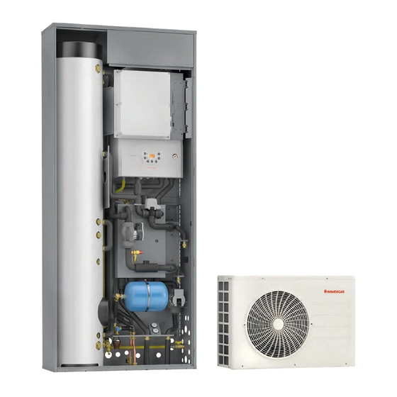
- Page 1 TRIO PACK Instructions and warnings Installer HYBRID User Maintenance technician 4 - 6 - 9 Heat pump consisting of: - indoor unit UI TPH - VICTRIX TERA 24 PLUS condensing boiler - outdoor condensing unit AUDAX PRO 4 - 6 - 9 V2...
-
Page 3: Table Of Contents
Cleaning and maintenance..........39 Technical data tables............76 Trio Pack Hybrid remote panel (main)......39 Trio Pack Hybrid 4 product fiche (in compliance 2.3.1 System use................39 with Regulation 811/2013)..........78 2.3.2 Operating mode..............40 Trio Pack Hybrid 6 product fiche (in compliance 2.3.3 Settings menu. -
Page 4: Dear Customer
Dear Customer Congratulations for having chosen a top-quality Immergas product, able to assure well-being and safety for a long period of time. As an Immergas customer you can also count on a Qualified Authorised After-Sales Technical Assistance Centre, prepared and updated to guar- antee constant efficiency of your appliance. -
Page 5: General Warnings
Read the instructions provided with the product carefully to ensure proper installation. • This instructions manual provides technical information for installing Immergas products. As for the other issues related to the installa- tion of products (e.g. safety at the workplace, environmental protection, accident prevention), it is necessary to comply with the provisions of the standards in force and the principles of good practice. -
Page 6: Safety Symbols Used
SAFETY SYMBOLS USED GENERIC HAZARD Strictly follow all of the indications next to the pictogram. Failure to follow the indications can generate hazard situations resulting in possible serious harm to the health of the operator and user in general, and/or serious material damage. ELECTRICAL HAZARD Strictly follow all of the indications next to the pictogram. -
Page 7: Installing The Indoor Unit
DESCRIPTION OF THE PRODUCT. This gas is ODOURLESS. Pay the utmost attention Trio Pack Hybrid 4-6-9 is a hybrid heat pump consisting of: - UI TPH indoor unit (hereinafter called, indoor unit or UI TPH). Strictly follow the instruction handbook of the... - Page 8 Installation Standards. Pay attention not to generate sparks as This indoor unit, if installed in an external wall, requires follows: the use of the special “Solar Container” to be fixed with - Do not remove the fuses while the the support brackets supplied together with the package unit is on.
-
Page 9: Solar Container Indoor Unit Main Dimensions
1.3 SOLAR CONTAINER INDOOR UNIT MAIN DIMENSIONS. Thermal solar systems circuit connecting bracket Connection inertial storage tank Inertial storage tank connection Height (mm) Width (mm) Depth (mm) Coolant connection inlet (LP2 - GP2) 2200... -
Page 10: Connection Template
CONNECTION TEMPLATE. Attention: the indicated values refer to the stickers applied inside the recessed frame. HEAT PUMP CONNECTION - INERTIAL STORAGE TANK - VICTRIX HYBRID OUTDOOR UNIT REAR CONNECTION (For details of values see Fig. 1) FLOW AND RETURN FOR INERTIAL STORAGE TANK LOWER CONNECTION RIGHT HAND SIDE CONNECTION... -
Page 11: Installation
INSTALLATION. Installation drawings key: Indoor unit composition. Unmistakeable component identification Ref. Description Q.ty Storage tank unit Sequential identification of the operation to perform Management electronics unit b1 Mount brackets for Solar Container b2 Mount brackets for Domus Container Identification of generic or not supplied component b3 Electronics unit mount bracket with hinges 1-zone hydronic group (or 2 zones optional) Accessories and screws... - Page 12 Installation operations. Before installing the pack, open the “Solar Container” completely by opening door (A) and blocking it to prevent it from getting in the way during the following installation procedures. Also remove the cover (B) and the side cover (C).
- Page 13 • Insert and block the storage tank unit retaining strip (d2) on the • Insert the storage tank unit (a) into the Solar Container with the screws fitted on the Solar Container. flange positioned on the right hand side and at the bottom, as shown in Fig.
- Page 14 • Fix bracket (b3) to bracket (b1) with screws (d3) (Fig. 7). • Bend the strip (d2) around the storage tank unit (a) and fasten it with the screw (D) (Fig. 8). • Tighten the brackets (b1) to the Solar Container using screws (d4) and washers (d5) as shown in Fig.
- Page 15 • Hang the hydronic unit (c) on the central bracket of the Solar ATTENTION. Container. Secure the position of the hydronic unit by fastening The fixing screws (d6 and d7) are pres- the screws (d6) on the central bracket (Fig. 9). ent in the connection kit of the device N.B.: in the event that the installer to be combined with the Trio Pack Hybrid.
- Page 16 Boiler installation operations. • Hang the boiler (e) on the bracket (E) installed previously, • Tighten the bracket (E) to the special upper cross member with (Fig. 10). screws (F).
- Page 17 N.B.: for easy electrical connection, move the power supply cable • Make the hydraulic connection between the storage tank unit (a), hydronic unit (c) and boiler (e), as shown in Fig. 11. of the boiler from the rear fairlead on the valve supporting plate to the front fairlead of the same.
-
Page 18: Gas Connection
GAS CONNECTION. Perform the boiler gas connection (e, Fig. 11) using the special pipe, cock and reducing coupling supplied and referring to the connection template on the Solar Container or Domus Contain- er (not supplied) and to the boiler operation and maintenance manual. -
Page 19: Hydraulic Connection
HYDRAULIC CONNECTION. SAFETY VALVE DRAIN. 8 bar domestic hot water safety valve. Perform the hydraulic connection of the Trio Pack Hybrid, re- ferring to the relative instruction sheet and to the connection Screw the fitting (d10) onto the safety valve. Screw the funnel template on the Solar Container. - Page 20 Domus Container). terms of pollution of drinking water, we recommend installing the IMMERGAS anti-backflow kit to be used upstream of the cold water • Fit the electrical panel (b) on the bracket (b3) as shown in Fig. 14.
-
Page 21: Electrical Connections To The Main Panel
ELECTRICAL CONNECTIONS TO THE MAIN PANEL. The connection cables must follow the prede- termined path using the special cable glands (a) (Fig. 16). Key (Fig. 16): - DHW probe connection (B2) (36-37, see the boiler wiring diagram) - 3-way valve connection (M50) - Heat pump flow probe connection (B1-HP) - System pump connection (M1) -
Page 22: Chiller Line Installation
1.10 CHILLER LINE INSTALLATION. As far as connecting the chiller line is concerned, all the instruc- tions contained in the outdoor condensing unit instructions Connect the chiller line of the outdoor unit as shown in Fig. 16. booklet must be followed. Connect the smaller pipe on the fitting (1) and the larger pipe on Make the connections directly on the indoor unit couplings (Fig. -
Page 23: Trio Pack Remote Panel
1.11 TRIO PACK REMOTE PANEL. 1.12 REMOTE PANEL INSTALLATION 4) Fix the body of the remote control to the mount template, engaging it with pressure. OPERATIONS. 5) After the pack has been powered, wait about 30 seconds before 1) Separate the fixing template from the body of the remote panel regulation so that communication between remote panel and using a screwdriver as a lever in the relative recess (Fig. - Page 24 (e.g. the a multi-pole circuit breaker with class Immergas Authorised After-Sales Technical Assistance Service). III overvoltage category in compliance For the main power supply to the appliance, never use adapters, with installation regulations.
- Page 25 Connections diagram.
-
Page 26: Zone Remote Control (Optional)
1.14 ZONE REMOTE CONTROL (OPTIONAL). DIP-Switch configuration table. This remote device is used to adjust the setpoints and to view the DIP 1-5 DIP 6-7 DIP 8 main information of the zone where it was configured. Connect the appliance as shown (Fig. 20). To correctly configure the device, set the parameters as described below: Assistance Menu ->... -
Page 27: Dominus (Optional)
If the outdoor condensing unit is positioned in an area that is not All Immergas chrono-thermostats are connected with 2 wires only. suitable for temperature reading, it is advisable to use an additional Carefully read the user and assembly instructions contained in external probe (Fig. -
Page 28: Temperature Control Setting
1.20 TEMPERATURE CONTROL SETTING. This can be done by enabling the external probe modulation in the menu By setting the parameters in the menus Zones/Enablings. Zones/Configuration The curves (Fig. 22, 23, 24 and 25) show the default settings in it is possible to automatically adjust the flow temperature of each the various operating modes available both with external probe zone according to the outdoor temperature. -
Page 29: Antifreeze Protection
1.21 ANTIFREEZE PROTECTION. 1.22 SYSTEM FILLING. Assembly instructions. Once the indoor unit is connected, fill the system using the filling - Wind the heating cable (d15) around the connection pipes and cock (Fig. 36 pos. 13). safety valve. The indoor unit has one incorporated automatic vent valve located on the manifold and one manual vent valve located on the filling Attention: the graphic representation of the heating cable is pipe (Fig. -
Page 30: Operating Limits
1.23 OPERATING LIMITS. 1.24 INDOOR UNIT START-UP (IGNITION). The appliance was designed to work in a specific range of outdoor After having installed the chiller lines on the outdoor condensing temperatures and at a specific maximum flow temperature. The unit, to commission the heat pump (the operations listed below chart (Fig. -
Page 31: Circulation Pump
1.25 CIRCULATION PUMP. Other functions: - The vent function of the pump is activated by pressing and The appliance is supplied with two circulators: the heat pump holding (3 seconds) the control key and automatically venting circulator, which deals with the heat exchange with outdoor con- the pump. - Page 32 Troubleshooting. Faults Causes Solutions Faulty electrical fuse Check the fuses Pump not working with power supply on. The pump is without voltage Eliminate the power supply cut-off Increase the system pressure within the allowed field Cavitation due to insufficient flow The pump generates noise.
- Page 33 Head available to the direct zone 1 system fixed speed. 1000 1200 1400 1600 1800 2000 2200 2400 2600 2800 3000 Flow rate (l/h) Key (Fig. 30): A = Head available to the system B = Absorbed power by the circulator (dotted area) Head available to the proportional head direct zone 1 system.
- Page 34 Head available to the constant head direct zone 1 system. 1000 1200 1400 1600 1800 2000 2200 2400 2600 2800 3000 Flow rate (l/h) Key (Fig. 32): A = Head available to the system B = Absorbed power by the circulator (dotted area) Head available to the fixed speed mixed zone 2 system - open mixing valve.
- Page 35 Head available to the proportional head mixed zone 2 system - open mixing valve. 1000 1200 1400 1600 1800 2000 2200 2400 2600 3000 2800 Flow rate (l/h) Key (Fig. 34): A = Head available to the system B = Absorbed power by the circulator (dotted area) Head available to the constant head mixed zone 2 system - open mixing valve.
-
Page 36: Domestic Hot Water Storage Tank Unit
• Recirculation kit. The appliance is designed for application of • Two multifunction relay kit (optional). The Kit makes it possible the recirculation kit. Immergas supplies a series of fittings and to enable the room dehumidifier control in neutral air or cooled attachments that allow connection between the appliance and air, or of a summer/winter diverter valve. -
Page 37: Main Components Kit
1.28 MAIN COMPONENTS KIT. Key (Fig. 36): - Storage tank draining cock / tap 13 - Filling cock / tap 25 - Plate heat exchanger - Sacrificial anode 14 - Manual air vent valve 26 - Liquid phase detection probe - Antifreeze thermostat 15 - DHW probe 27 - Heat pump return probe... -
Page 38: Instructions For Use And Maintenance
INSTRUCTIONS FOR USE AND The use of components involving use MAINTENANCE. of electrical power requires some fun- damental rules to be observed such as: GENERAL WARNINGS. - do not touch the appliance with wet or moist Never expose the indoor unit to direct parts of the body;... -
Page 39: Cleaning And Maintenance
CLEANING AND MAINTENANCE. To preserve system integrity and keep the distinguishing safety features, performance and reliability unchanged over time, you must execute maintenance operations on a yearly basis in compliance with what is stated in the point regarding “annual appliance check and maintenance”. TRIO PACK HYBRID REMOTE PANEL (MAIN). -
Page 40: Operating Mode
2.3.2 Operating mode. Also, depending on the system's configuration, the main screen displays various information regarding the system, amongst which: The indoor unit can work in the following modes: Status Description - STAND-BY ( Room humidity value (if humidity - SUMMER ( probe is present) - SUMMER WITH COOLING ( External temperature value (external... - Page 41 In the first case, the system works in the following way: The domestic hot water can be produced with the heat pump or Manual adjustment (Man) with the boiler. The central heating / C.H. request is adjusted according to a The system automatically manages the activation of the generators fixed room setpoint.
- Page 42 Clock and Programs/Set date and time. Automatic adjustment (Auto) There are two reference setpoints: Setting date and time Cooling/Set cooling comfort. Cooling/Cooling economy set. HOUR 22:22 By associating a calendar with the relevant zone program, it is possible to determine the time slots for activating the cooling MONTH comfort set.
- Page 43 On the menu Contact the manufacturer of the radiant panels for the Zone/Information thermal shock characteristics and its correct execution. it is possible to identify the status of the various con- trols managing the central heating / C.H.. To be able to activate the function there must be no remote control connected, while in case of system di- •...
-
Page 44: Settings Menu
2.3.3 Settings menu. The following menus refer to firmware rev. 1.0. Press the “Menu” button to access a list of variables that enable Menu you to customise use of the system. To browse the menus, which can be accessed by pressing the rela- Set Point Zone 1 [ ... - Page 45 Menù Set Point Zone 2 Menu (present with 2 zones kit optional) Personalized Voice menu Description Range Default value Set comfort heat Room temperature in central heating zone 2 Comfort mode 15 - 35 °C Set economy heat Room temperature in central heating zone 2 Economy mode 5 - 25 °C Set manual heat Room temperature in central heating zone 2 Manual mode...
- Page 46 Time and Program Personalized Voice menu Description Range Default value CAL1, CAL2, Zone 2: Tuesday CAL1 CAL3,CAL4 CAL1, CAL2, Zone 2: Wednesday CAL1 CAL3,CAL4 CAL1, CAL2, Zone 2: Thursday CAL1 CAL3,CAL4 CAL1, CAL2, Zone 2: Friday CAL1 CAL3,CAL4 CAL1, CAL2, Zone 2: Saturday CAL1 CAL3,CAL4...
- Page 47 User Menu Personalized Voice menu Description Range Default value Dehum. zone 1 disable It allows to disable the zone 1 dehumidifier according to the set time slot Yes/No Dehum. zone 1 disab. start Allows to set when disabling starts. 0 - 23 Dehum.
-
Page 48: Dhw (Domestic Hot Water) Set Setting
Historical alarm code Description Displays the history log of the last 10 anomalies, see Par. 2.4.5. Service Menu Personalized Voice menu Description Range Default value Password protected menu dedicated to a qualified technician Language Menu Personalized Voice menu Description Range Default value Language... - Page 49 Error Anomaly Cause System status / Solution Code signalled Flow probe The board detects an anomaly on the flow NTC probe. The system does not start (1). anomaly Domestic hot The hydronic module is unable to produce water probe The board detects an anomaly on the domestic hot water probe. domestic hot water (1).
- Page 50 Error Anomaly Cause System status / Solution Code signalled Zone 2 The system does not dehumidify in the dehumidifier fault Anomaly coming from the dehumidifier (optional) in zone 2 relative zone (1) alarm Reset system When the default parameters are restored, the system needs to be alarm –...
- Page 51 List of boiler anomalies. List of anomalies outdoor condensing unit. If the outdoor condensing unit is faulty, the error code is dis- If the condensing unit is faulty, the error code is displayed in the played in the middle of the control panel (Fig. 37) with code 9xxx middle of the control panel (Fig.
- Page 52 Error Anomaly System status / Solution Code signalled Cooling operation stopped (outdoor temperature below 9°C) Error of outdoor condensing unit fan no.1 Check the chiller cycle. Check the compressor connections. Compressor start-up error (Inverter) Check the resistances between the different phases of the compressor. Check the inlet current.
- Page 53 Error Anomaly System status / Solution Code signalled Not present Not present Not present Indoor unit error. Not used Check indoor unit. Indoor unit error. Not used Check indoor unit. Indoor unit error. Not used Check indoor unit. Indoor unit error. Not used Check indoor unit.
-
Page 54: Using The Secondary Zone Remote Panel (Optional)
USING THE SECONDARY ZONE DECOMMISSIONING. REMOTE PANEL (OPTIONAL). In the event of permanent system shutdown, contact professional staff for the procedures and ensure that the electrical, water supply For general operation of the zone remote panel, see the relative lines are previously shut off and disconnected and that the solar instruction booklet. -
Page 55: Maintenance And Initial Check Instructions
- check the activation of the main switch located upstream of the indoor unit; fail to meet the current regulations. in regard to the above, only use original Immergas spare parts when replacing components. - ensure activation of all adjustment devices; - ensure production of domestic hot water;... -
Page 56: Yearly Equipment Check And Maintenance
YEARLY EQUIPMENT CHECK AND EXTERNAL UNIT FINNED AIR COIL MAINTENANCE. MAINTENANCE. The following checks and maintenance should be We recommend regularly inspecting the finned air coils performed once a year to ensure operation, safety and to check the level of fouling. efficiency of the appliance over time. -
Page 57: Hydraulic Diagram
HYDRAULIC DIAGRAM. Key: Storage tank draining cock / tap Storage tank / Cylinder Domestic hot water vessel shut-off cock Outdoor condensing unit 8 l domestic hot water expansion vessel Plate heat exchanger Hydraulic manifold System flow-meter 22a - Manifold flow sector System circulator pump 22b - Manifold return sector 3 bar safety valve... -
Page 58: Wiring Diagram
WIRING DIAGRAM. Practical power supply diagram. - Page 59 Main connection diagram.
- Page 60 X102 and X105 Terminal board connections diagram.
- Page 61 Zone connection diagram.
- Page 62 Zone 2 connection diagram. Colour code key: - Closed BK - Black BL - Blue - Common - Open BR - Brown Key: - Main panel G/Y - Green-Yellow M10-2 - Zone 2 circulator - Supervision board GY - Grey - Zone 2 connector B3-2 - Mixed zone 2 flow probe M31-2 - Zone 2 mixing valve...
- Page 63 Expansion kit connection diagram.
-
Page 64: Possible Problems And Their Causes
POSSIBLE PROBLEMS AND THEIR SYSTEM PROGRAMMING. CAUSES. The water heater is set up for possible programming of several operation parameters. By modifying these parameters as described Maintenance operations must be carried out by an below, the system can be adapted according to specific needs. authorised company (e.g. - Page 65 Service Menu -> Definition of Zone 2 (present with 2 zones kit optional) Personalized Voice menu Description Range Default value - Hot Mode Establishes the zone 2 operating mode. - Cold Hot + Cold - Hot + Cold Enables operation with a remote zone control To be enabled if a remote zone control is used in zone 2 as room control and not the remote panel, which is used in zone 1 (main zone).
- Page 66 Service Menu -> System definition Personalized Voice menu Description Range Default value 0 = Disabled. 1 = Zone 1 in neutral air dehumidification contact. 2 = Zone 2 in neutral air dehumidification contact. Multifunction relay 1 0 - 5 3 = Zone 1 in cooled air dehumidification contact. 4 = Zone 2 in cooled air dehumidification contact.
- Page 67 Service Menu -> Thermoregulation -> Thermoregulation heat Personalized Voice menu Description Range Default value Without the external probe it defines the minimum flow temperature that can be set by the user. With the external probe present it defines the Zone 1 Set min flow 20 ÷...
- Page 68 Service Menu -> DHW definition Personalized Voice menu Description Range Default value It establishes at which temperature different must the system activate to DHW hysteresis 3 - 10 °C heat the domestic hot water with respect to the set value. Antilegionella Enables the anti-legionella function.
- Page 69 Heat pump status. HP Flowmeter Flow meter HP circulator instantaneous speed. System State Status parameter Technical parameter (only for Immergas Assistance). Integration State Integration state parameter Technical parameter (only for Immergas Assistance). Output status Output status parameter Technical parameter (only for Immergas Assistance).
- Page 70 Service Menu -> Manual Personalized Voice menu Description Range Default value Deaeration enab. Enables the deaeration function of the system. Yes / No DHW Three-way Manual activation of the DHW (Domestic hot water) 3-way. On / Off Enable boiler Manual activation of the boiler. On / Off Flow temp.
-
Page 71: Programming And Use Of The Zone Remote Panel
PROGRAMMING AND USE OF THE ZONE REMOTE PANEL. Trio Pack Hybrid remote panel on zone 1 and Remote zone panel on zone 2. Zone 1 Zone 2 Trio Pack Hybrid remote panel Remote zone control Assistance Menu -> System definition -> Main zone: ..........1 Assistance Menu ->... -
Page 72: First Ignition Parameter Setting
It is suggested to set the following values: IT IS possible to customise the operation of each individual zone. Trio Pack Hybrid 4: Speed = 60% Each zone can be enabled for a single operating mode, modifying Trio Pack Hybrid 6: Speed = 70%... -
Page 73: Dhw (Domestic Hot Water) Boost Function
3.15 PUMP ANTI-BLOCK FUNCTION. Zone 1-2 Definition/Room probe modul. The system flow temp drops (it rises in case of cooling) when the The hydronic module has a function that starts up the pump at room temp. approaches the room setpoint. Modulation with room least once every 24 hours for 30 seconds in order to reduce the probe can only be enabled in the presence of a zone remote device. -
Page 74: Conjunction Mode
(SUMMER / WINTER) (OPTIONAL). the external supervision devices such as Dominus or other types of home automation systems (not supplied by Immergas). Valid only in conjunction with relay kit 2. For the configuration, it is necessary to modify the parameter: System definition/System supervision. -
Page 75: Yearly Maintenance
3.28 YEARLY MAINTENANCE. Vent Any air present in the system must be bled: - Check the integrity of the storage tank / cylinder magnesium anode. - upon start-up (after filling) - Check tightness of the assembly elements (screws, bolts, plugs, - if necessary, e.g. -
Page 76: Technical Data
TECHNICAL DATA. TECHNICAL DATA TABLES. The following data refers to product data. Trio Pack Trio Pack Trio Pack Hybrid 4 Hybrid 6 Hybrid 9 Nominal data for low temperature applications (A7/W35) * Nominal central heating output 4.40 6.00 9.00 Absorption 0.85 1.22 1.87... - Page 77 Appliance data. Trio Pack Trio Pack Trio Pack Hybrid 4 Hybrid 6 Hybrid 9 Dimensions of Internal Unit 950x2200x350 - 975x2110x365 (Width x Height x Depth) Solar - Domus Maximum heating temperature °C Adjustable central heating temperature (operating field) °C 20-85 Cooling adjustable temperature (operating field) °C...
-
Page 78: Trio Pack Hybrid 4 Product Fiche (In Compliance With Regulation 811/2013)
TRIO PACK HYBRID 4 PRODUCT FICHE (IN COMPLIANCE WITH REGULATION 811/2013). For proper installation of the appliance refer to chapter 1 of this For proper maintenance refer to chapter 3 of this booklet (for booklet (for the installer) and current installation regulations. - Page 79 Parameter Unit Value η (energy efficiency) V40 (water mixed at 40°C) Low temperature (30/35). Value Colder zones Average zones Hotter zones Annual energy consumption for the central heating mode (Q kWh\year 2771 2237 1127 Room central heating seasonal efficiency (η ηs % Nominal heat output High temperature (47/55).
- Page 80 For mixed central heating appliances with a heat pump Stated load profile Water central heating energy efficiency η Daily electrical power consumption 3.92 kWh Daily fuel consumption elec fuel Annual energy consumption kWh Annual fuel consumption Contact information Immergas S.p.A. via Cisa Ligure n.95...
-
Page 81: Trio Pack Hybrid 6 Product Fiche (In Compliance With Regulation 811/2013)
TRIO PACK HYBRID 6 PRODUCT FICHE (IN COMPLIANCE WITH REGULATION 811/2013). For proper installation of the appliance refer to chapter 1 of this For proper maintenance refer to chapter 3 of this booklet (for booklet (for the installer) and current installation regulations. the maintenance technician) and adhere to the frequencies and methods set out herein. - Page 82 Parameter Unit Value η (energy efficiency) V40 (water mixed at 40°C) Low temperature (30/35). Value Colder zones Average zones Hotter zones Annual energy consumption for the central heating mode (Q kWh\year 3305 2673 1258 Room central heating seasonal efficiency (η ηs % Nominal heat output High temperature (47/55).
- Page 83 For mixed central heating appliances with a heat pump Stated load profile Water central heating energy efficiency η 118.0 Daily electrical power consumption 4.14 kWh Daily fuel consumption elec fuel Annual energy consumption kWh Annual fuel consumption Contact information Immergas S.p.A. via Cisa Ligure n.95...
-
Page 84: Trio Pack Hybrid 9 Product Fiche (In Compliance With Regulation 811/2013)
TRIO PACK HYBRID 9 PRODUCT FICHE (IN COMPLIANCE WITH REGULATION 811/2013). For proper installation of the appliance refer to chapter 1 of this For proper maintenance refer to chapter 3 of this booklet (for booklet (for the installer) and current installation regulations. the maintenance technician) and adhere to the frequencies and methods set out herein. - Page 85 Parameter Unit Value η (energy efficiency) V40 (water mixed at 40°C) Low temperature (30/35). Value Colder zones Average zones Hotter zones Annual energy consumption for the central heating mode (Q kWh\year 5234 3900 1863 Room central heating seasonal efficiency (η ηs % Nominal heat output High temperature (47/55).
- Page 86 For mixed central heating appliances with a heat pump Stated load profile Water central heating energy efficiency η Daily electrical power consumption 8.26 kWh Daily fuel consumption elec fuel Annual energy consumption 1706 kWh Annual fuel consumption Contact information Immergas S.p.A. via Cisa Ligure n.95...
-
Page 87: Parameters For Filling In The Package Fiche
PARAMETERS FOR FILLING IN THE sheets of the products used to make up the assembly (e.g. solar devices, integration heat pumps, temperature controllers). PACKAGE FICHE. Use board (Fig. 63) for “assemblies” related to the central heating Should you wish to install an assembly starting from the Trio Pack mode (e.g.: heat pump + temperature controller). - Page 88 Parameters to fill in the low temperature package fiche (30/35). Parameters to fill in the average temperature package fiche (47/55). Trio Pack Hybrid 4 Trio Pack Hybrid 4 Parameter Colder zones Average zones Hotter zones Parameter Colder zones Average zones Hotter zones "I"...
- Page 89 Room central heating system package fiche. Room central heating seasonal energy efficiency of the heat pump ______ Class I = 1 %, Class II = 2 %, Temperature control Class III = 1.5 %, Class IV = 2 %, From temperature Class V = 3 %, Class VI = 4 %, control board Class VII = 3.5 %, Class VIII = 5 %...
- Page 92 This instruction booklet is made of ecological paper immergas.com Immergas S.p.A. 42041 Brescello (RE) - Italy Tel. 0522.689011 Fax 0522.680617...