Table of Contents
Advertisement
Quick Links
Technical Documentation
General features.
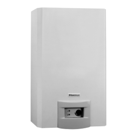
CAESAR Star is a room-sealed water heater featuring
an electronic flame modulation system for regulating
the temperature thanks to a microprocessor-controlled
modulation board and flow and temperature sensors.
CAESAR 14 Star features standard electronic burner
ignition and a wet combustion chamber copper
exchanger.
Notwithstanding its very compact size, the appliance
has a power of 21,000 Kcal/h (24.4 kW) corresponding
to a flow of 14 l/min with ∆T 25°C.
CAESAR 14 Star is factory set for connecting to the
broad range of couple-on aspiration and exhaust kits
with silicone seals and, thanks to a special cover kit
(optional), it can be installed in open chamber and fan-
assisted configuration (B
is an antifreeze safety device that protects it against
temperatures as low as -15°C.
STCS ed 07/02
CAESAR STAR
). Another optional feature
22
Technical Documentation
Instantaneous wall-hung room
sealed fan-assisted water heater.
CAESAR 14 Star
1
CAESAR Star
Advertisement
Table of Contents

Related Manuals for Immergas CAESAR 14 Star


Summary of Contents for Immergas CAESAR 14 Star
- Page 1 21,000 Kcal/h (24.4 kW) corresponding to a flow of 14 l/min with ∆T 25°C. CAESAR 14 Star is factory set for connecting to the broad range of couple-on aspiration and exhaust kits with silicone seals and, thanks to a special cover kit...
-
Page 2: Main Dimensions
Technical Documentation Technical Documentation Main dimensions. Key: U - domestic hot water outlet G - gas supply E - d.h.w. inlet V - power connections " 4 " 2 " 2 STCS ed 07/02 CAESAR Star... - Page 3 Technical Documentation Technical Documentation CAESAR Star main component parts. Key: 1 - Sealed chamber 9 - Flow limiter 2 - Fume expulsion fan 10 - 10 bar safety valve / one way valve 3 - D.h.w. exchanger 11 - Flow meter 4 - Ignition/detection glow electrode 12 - Draught diverter.
-
Page 4: Hydraulic Circuit
Technical Documentation Technical Documentation Hydraulic circuit. Key: 1 - Fume extraction fan 2 - Sealed chamber 3 - Exchanger 4 - Main burner 5 - Gas valve 6 - D.h.w. adjustment NTC probe 7 - Overheat. temp. safety thermostat 8 - Air pressure switch 9 - Draught diverter 10 - Exchanger safety thermostat 11 - Flow limiter... -
Page 5: Operation
Technical Documentation Technical Documentation Hydraulic circuit. The hydraulic circuit with relevant control and safety Safety devices and controls. devices is engaged every time there is a request for domestic hot water. Flow meter (1). This is a rotating magnetic sensor fitted at the cold water flow inlet. -
Page 6: Gas Circuit
Technical Documentation Technical Documentation Gas circuit. The circuit consists of an atmospheric burner and a Burner. modulating type valve for gas combustion and gas flow The burner consists of 12 horizontal venturi pipes (4) adjustment respectively. in which the gas is injected by an equal number of nozzles (6) mounted on the special header (7). -
Page 7: Gas Adjustments
Technical Documentation Technical Documentation Gas adjustments. Max and minimum gas pressure adjustments can be Changing type of gas. made by means of the gas valve respecting the values Adaptation to a type of gas different to that for which shown on the tables relating to the type of the boiler is intended, can be done by using the special corresponding gas. - Page 8 Technical Documentation Technical Documentation Fume circuit. Operation. The products of combustion, after investing the water- It is controlled by the adjustment board and its gas exchanger (3), are conveyed to a draught diverter operation coincides with that of the burner. (5) on top of which the fume extractor (fan) (1) is fitted.
- Page 9 Technical Documentation Technical Documentation Extraction and exhaust systems. The CAESAR Star is set for connecting to the coupling extraction/exhaust ducts and can be installed in sealed chamber fan-assisted configuration (type C) or, thanks to a special kit, in open chamber fan-assisted version (type B As regards the load losses relating to each accessory and the various possible combinations and the use of...
- Page 10 Technical Documentation Technical Documentation Sealed chamber fan-assisted configuration (type C). Exhaust. Connection to the exhaust pipes is by means of a flange (1) or a flanged bend to be fitted on the centre hole (6) on the top section of the sealed chamber, placing in between a special shaped seal (5).
- Page 11 Technical Documentation Technical Documentation Vertical concentric slot-in kit Ø 60/100. The exhaust pipe (Ø 60 mm) is fitted inside the extraction pipe (Ø 100 mm). Connection to the boiler is by means of a flange (2) which, by means of the necessary extensions, must be connected to the extraction and exhaust end piece 60/100 (5) with aluminium tile.
-
Page 12: Electrical Circuit
Technical Documentation Technical Documentation Electrical circuit. 230Vac 50HZ Antifreeze kit power power supply supply Key: B1 - D.h.w. NTC probe B2 - Flow measurer Yellow/green E1 - Igntion/detection glow electrode Brown Blue E2 - Linit thermostat E3 - Overheat.safety thermo H1 - Flame presence LED ON/OFF D.H.W. -
Page 13: Low-Voltage Circuit
Technical Documentation Technical Documentation Loads. This is controlled by the ignition circuit of the adjustment board which provokes Ignition Electrode an electric spark between its end and the burner surface that ignites the air/ (E1) gas mix. The electrode also acts as a detection glow electrode. This is powered by the ignition circuit of the adjustment board when the burner Gas valve has to be ignited. - Page 14 Technical Documentation Technical Documentation CAESAR Star electrical circuit. MAINS VOLTAGE VOLT. COMMAND LOGIC MICROPROCESSOR IGNITION SECTION Operation. When master switch (S4) is in ON position, it powers the low-voltage circuit and enables appliance operation. If hot water is run the flow measuring device (B2) trips and this gives the signal for burner ignition.
- Page 15 Technical Documentation Technical Documentation Modulation board. FUSE IGNITION TRANSF. ON/OFF D.H.W. ADJ. NATURAL GAS / LPG MICROPROCESSOR Primary Secundary TOWN Inside the CAESAR Star control box is a means of LEDs, shows the operating condition of the microprocessor controlled electronic board that appliance, indicating any tripping of safety devices.
- Page 16 Technical Documentation Technical Documentation Inputs. Enables the ignition circuit of the board to detect the presence of a flame on Ignition/Detection the burner. If this does not operate, the no ignition lock trips, signalled by the electrode lighting up of red LED H2. (E1) Any operation prior to burner ignition is indicated by the flashing of red LED Integrated in a single device.
- Page 17 Technical Documentation Technical Documentation Outputs. This is a positive square-wave signal with variable ON-OFF ratio (duty-cycle) Modulator coil that controls the modulation coil of the gas valve and makes it possible to alter (Y2) gas pressure to the burner. Ignition/Detection This is a high voltage signal (about 16 kV) for energising the ignition electrode electrode on the boiler.
-
Page 18: Safety Devices
Technical Documentation Technical Documentation Safety devices. If, within 10 seconds from the start of the ignition cycle, the detection electrode (E1) fails to detect the presence of a flame on the burner, appliance operation is stopped. No ignition stop To start the appliance again, the master switch (S4) will have to be moved to OFF and afterwards, after returning the switch to ON, the hot water will have to be run. - Page 19 Technical Documentation Technical Documentation CAESAR Star operation sequence. Power on Master switch (S4) in ON position. Power circuit adjustment The closing of master switch (S4) powers the modulating board and enables operation. Detection of d.h.w. request (Flow measuring device) Running of d.h.w. Ignition circuit power If the temperature of the d.h.w.
-
Page 20: Technical Details
Technical Documentation Technical Documentation Technical details. CAESAR Star technical details. Nominal heat output kW (kcal/h) 27,6 (23730) Minimum heat output capacity kW (kcal/h) 8,9 (7689) Nominal heat output (working) kW (kcal/h) 24,4 (21000) Minimum heat output (working) kW (kcal/h) 7,0 (6000) Working thermal efficiency at nominal output 88,5 Loss of heat at casing with burner on... - Page 21 Technical Documentation Technical Documentation CAESAR Star variable heat output. NATURAL GAS (G20) BUTANE (G30) PROPANE (G31) HEAT HEAT BURNER GAS BURNER NOZZLE BURNER GAS BURNER NOZZLE BURNER GAS BURNER NOZZLE OUTPUT OUTPUT FLOW PRESSURE FLOW PRESSURE FLOW PRESSURE (kcal/h) (kW) (mbar) (mm H (kg/h) (mbar) (mm H...