
Related Manuals for Comtrend Corporation CT-5071E


Summary of Contents for Comtrend Corporation CT-5071E
- Page 1 CT-5071E ADSL2+ Ethernet Router User’s Manual Version A4.0, May 07, 2007 261063-011...
- Page 2 Preface This manual provides information to network administrators. It covers the installation, operation and applications of the ADSL router. The reader reading this manual is presumed to have a basic understanding of telecommunications. For product update, new product release, manual revision, software upgrade, technical...
- Page 3 Copyright Copyright© 2007 Comtrend Corporation. All rights reserved. The information and messages contained herein are proprietary to Comtrend Corporation. No part of this document may be translated, transcribed, reproduced, in any form, or by any means without prior written permission by Comtrend Corporation.
-
Page 4: Table Of Contents
Table of Contents CHAPTER 1 INTRODUCTION................. 5 ......................5 EATURES ....................... 6 PPLICATION LED I ................. 7 RONT ANEL NDICATORS CHAPTER 2 INSTALLATION.................. 8 .................. 8 ARDWARE NSTALLATION CHAPTER 3 LOGIN VIA THE WEB BROWSER ........9 IP A ......................9 DDRESS .................... - Page 5 ..................50 6.4.2 Parental Control ....................52 6.4.3 IP Filtering ......................55 OUTING ..................55 6.5.1 Default Gateway ....................56 6.5.2 Static Route DNS........................57 ....................57 6.6.1 DNS Server ................... 57 6.6.2 Dynamic DNS DSL ........................60 CHAPTER 7 DIAGNOSTICS ................
-
Page 6: Chapter 1 Introduction
Chapter 1 Introduction The CT-5071E is a wired Local Area Network ADSL2+ router. One 10/100 Base-T Ethernet port provides wired LAN. The CT-5071E ADSL router provides state of the art security features such as Firewall and VPN pass through. The CT-5071E is designed for residential applications that require wired connectivity to an ADSL broadband network. -
Page 7: Application
Application The following diagram depicts the application of the CT-5071E. -
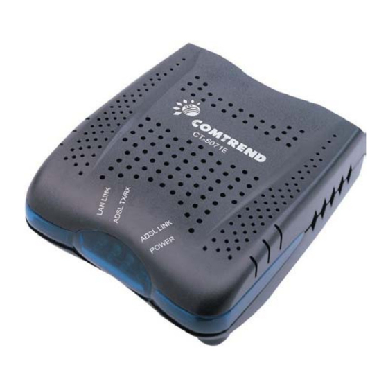
Page 8: Front Panel Led Indicators
Front Panel LED Indicators The front panel LEDs are shown in the picture below, followed by an explanation in the table below. Color Mode Function POWER Green The router is powered up. The router is powered down. Green The ADSL link is established. The ADSL link is not established ADSL LINK Green... -
Page 9: Chapter 2 Installation
Chapter 2 Installation Hardware Installation In the rear panel, there is a reset button. It is used to load the factory default settings. Hold down the button until the LED’s start blinking simultaneously (about 5 seconds). After the device has booted successfully, the factory default settings are retrieved. -
Page 10: Chapter 3 Login Via The Web Browser
The default IP address of the CT-5071E (LAN port) is 192.168.1.1. To configure the CT-5071E for the first time, the configuration PC must have a static IP address within the 192.168.1.x subnet. Follow the steps below to configure your PC IP address to use subnet 192.168.1.x. -
Page 11: Login Procedure
3.2 Login Procedure Perform the following steps to bring up the Web user interface and configure the CT- 5071E. To log on to the system from the Web browser, follow the steps below: STEP 1: Start your Internet browser. Type the IP address for the router in the Web address field. -
Page 12: Default Settings
3.2.1 Default Settings During power on initialization, the CT-5071E initializes all configuration attributes to default values. It will then read the configuration profile from the Permanent Storage section on the flash memory. The default attributes are overridden when identical attributes with different values are configured. The configuration profile in Permanent Storage can be created via the Web user interface or telnet user interface, or other management protocols. -
Page 13: Chapter 4 Device Info
Chapter 4 Device Info After login, the Device Info screen appears as shown. Note: The selections available on the left side of menu are based upon the configured connection. -
Page 14: Wan
Click WAN on the Device Info menu bar to display the configured PVC(s) and the status. VPI/VCI Shows the values of the ATM VPI/VCI Con. ID Shows the connection ID Category Shows the ATM service classes Service Shows the name for WAN connection Interface Shows connection interfaces Protocol... -
Page 15: Statistics
Statistics Selection of the Statistics screen provides statistics for the Network Interface of LAN, WAN, ATM and ADSL. All statistics screens are updated every 15 seconds. -
Page 16: Lan Statistics
4.2.1 LAN Statistics The Network Statistics screen shows interface statistics for ATM AAL5 interface and Ethernet interfaces. (The Network Statistics screen shows interface statistics for LAN of Ethernet interfaces. This shows byte transfer, packet transfer, Error and Drop statistics for the LAN interface.) -
Page 17: Wan Statistics
4.2.2 WAN Statistics Service Shows the service type VPI/VCI Shows the values of the ATM VPI/VCI Protocol Shows the connection type, such as PPPoE, PPPoA, etc. Interface Shows connection interfaces Received/Transmitted - Bytes Rx/TX (receive/transmit) packet in Byte Pkts Rx/TX (receive/transmit) packets Errs Rx/TX (receive/transmit) the packets which are errors,... -
Page 18: Atm Statistics
4.2.3 ATM statistics The following figure shows the ATM statistics screen. ATM Interface Statistics Field Description In Octets Number of received octets over the interface Number of transmitted octets over the interface OUT OCTETS In Errors Number of cells dropped due to uncorrectable HEC errors In Unknown Number of received cells discarded during cell header... - Page 19 ATM AAL5 Layer Statistics over ADSL interface Field Description In Octets Number of received AAL5/AAL0 CPCS PDU octets Out Octets Number of received AAL5/AAL0 CPCS PDUs octets transmitted In Ucst Pkts Number of received AAL5/AAL0 CPCS PDUs passed to a higher-layer for transmission Out Ucast Pkts Number of received AAL5/AAL0 CPCS PDUs received from a...
-
Page 20: Adsl Statistics
4.2.4 ADSL Statistics The following figure shows the ADSL Network Statistics screen. Within the ADSL Statistics window, a bit Error Rate Test can be started using the ADSL BER Test button. The Reset button resets the statistics. - Page 21 Field Description Mode Modulation protocol G.DMT or T1.413 Type Channel type Interleave or Fast Line Coding Line Coding format, that can be selected G.dmt, G.lite, T1.413, ADSL2, Annex L and Annex M Status Lists the status of the DSL link Link Power State Link output power state.
-
Page 22: Route
4.2.5 Route Choose Route to display the routes that the route information has learned. 4.2.6 ARP … Click ARP to display the ARP information. -
Page 23: Bridging
4.2.7 Bridging Click Bridging to display the bridge entries information. -
Page 24: Igmp Proxy
4.2.8 IGMP Proxy Click IGMP Proxy to display the IGMP proxy entries information. -
Page 25: Chapter 5 Quick Setup
If the service provider provides PPPoE service, then the connection selection depends on whether the LAN-side device (typically a PC) is running a PPPoE client or whether the CT-5071E is to run the PPPoE client. The CT-5071E can support both cases simultaneously. -
Page 26: Auto Quick Setup
Auto Quick Setup The auto quick setup requires the ADSL link to be up. The ADSL router will automatically detect the PVC. You only need to follow the online instructions that you are prompted. Note: As there is a bridge mode PVC set up (based on the default settings of this device,) it needs to be removed in order for the Quick Setup menu option to be displayed. -
Page 27: Manual Quick Setup
Manual Quick Setup STEP 1: Click Quick Setup and un-tick the DSL Auto-connect checkbox to enable manual configuration of the connection type. Un-tick this checkbox to enable manual setup and display the following screen. STEP 2: Enter the Virtual Path Identifier (VPI) and Virtual Channel Identifier (VCI). Select Enable Quality Of Service if required. - Page 28 STEP 4: Click Next to display the following screen. Choosing different connection types pops up different settings requests. Enter appropriate settings that are requested by your service provider. The following descriptions state each connection type setup separately.
-
Page 29: Ppp Over Atm (Pppoa) And Ppp Over Ethernet (Pppoe)
5.2.1 PPP over ATM (PPPoA) and PPP over Ethernet (PPPoE) 1. Select the PPP over ATM (PPPoA) or PPP over Ethernet (PPPoE) button and click Next. The following screen appears: PPP USERNAME/PPP PASSWORD The PPP Username and the PPP password requirement are dependent on the particular requirements of the ISP or the ADSL service provider. - Page 30 Disconnect if no activity The CT-5071E can be configured to disconnect if there is no activity for a period of time by selecting the Disconnect if no activity check box. When the checkbox is ticked, you need to enter the inactivity timeout period. The timeout period ranges from 1 minute to 4320 minutes.
- Page 31 3. After entering your settings, select Next. The Device Setup page allows the user to configure the LAN interface IP address and DHCP server. If the user would like this ADSL router to assign dynamic IP addresses, DNS server and default gateway to other LAN devices, select the radio box Enable DHCP server on the LAN to enter the starting IP address and end IP address and DHCP lease time.
- Page 32 The Web UI will not respond until the system is brought up again. After the system is up, the Web UI will refresh to the Device Info page automatically. The CT-5071E is ready for operation and the LEDs display as described in the LED description tables.
-
Page 33: Mac Encapsulation Routing (Mer)
5.2.2 MAC Encapsulation Routing (MER) To configure MER, do the following. 1. Select Quick Setup and click Next. 2. Enter the PVC Index provided by the ISP and click Next and click Next 3. Select the MAC Encapsulation Routing (MER) radio button, and click Next. The following screen appears. - Page 34 4. Click Next to display the following screen appears. Enable NAT checkbox: If the LAN is configured with a private IP address, the user should select this checkbox. The NAT submenu on the left side main panel will be displayed after reboot. The user can then configure NAT-related features after the system comes up.
- Page 35 5. Upon completion, click Next. The following screen appears. The Device Setup page allows the user to configure the LAN interface IP address and DHCP server. If the user would like this ADSL router to assign dynamic IP addresses, DNS server and default gateway to other LAN devices, select the radio box Enable DHCP server on the LAN to enter the starting IP address and end IP address and DHCP lease time.
- Page 36 The Web UI will not respond until the system is brought up again. After the system is up, the Web UI will refresh to the Device Info page automatically. The CT-5071E is ready for operation and the LEDs display as described in the LED description tables.
-
Page 37: Ip Over Atm (Ipoa)
5.2.3 IP Over ATM (IPoA) To configure IP Over ATM, 1. Select Quick Setup and click Next. 2. Enter the PVC Index and click Next. 3. Type the VPI and VCI values provided by the ISP and click Next. 4. Select the IP over ATM (IPoA) radio button and click Next. The following screen appears. - Page 38 Enable NAT checkbox If the LAN is configured with a private IP address, the user should select this checkbox. The NAT submenu on the left side main panel will be displayed after reboot. The user can then configure NAT-related features after the system comes up.
- Page 39 The user must configure the IP Address and the Subnet Mask. To use the DHCP service on the LAN, select the Enable DHCP server checkbox, and enter the Start IP addresses, the End IP address and DHCP lease time. This configures the router to automatically assign IP addresses, default gateway address and DNS server addresses to each of your PCs.
- Page 40 The Web UI will not respond until the system is brought up again. After the system is up, the Web UI will refresh to the Device Info page automatically. The CT-5071E is ready for operation and the LEDs display as described in the LED description tables.
-
Page 41: Bridging
5.2.4 Bridging Select the bridging mode. To configure Bridging, do the following. 1. Select Quick Setup and click Next. 2. Enter the PVC Index and click Next. 3. Type in the VPI and VCI values provided by the ISP and click Next. 4. - Page 42 6. Click the Next button The following screen will be displayed. The WAN Setup-Summary screen presents the entire configuration summary. Click Save/Reboot if the settings are correct. Click Back if you wish to modify the settings.
-
Page 43: Chapter 6 Advanced Setup
Chapter 6 Advanced Setup This chapter explains: WAN, LAN, Routing and DSL. VPI/VCI ATM VPI (0-255) / VCI (32-65535) Con. ID ID for WAN connection Category ATM service category, e.g. UBR, CBR… Service Name of the WAN connection Interface Name of the interface for WAN Protocol Shows bridge or router mode IGMP... -
Page 44: Lan
Configure the DSL Router IP Address and Subnet Mask for LAN interface. Save button only saves the LAN configuration data. Save/Reboot button saves the LAN configuration data and reboots the router to make the new configuration effective. IP Address: Enter the IP address for the LAN port. Subnet Mask: Enter the subnet mask for the LAN port. -
Page 45: Nat
Note: This option is not available for bridge mode. To display the NAT function, you need to enable the NAT feature in the WAN Setup. 6.3.1 Virtual Servers Note: This option is not available for Bridge mode. Virtual Server allows you to direct incoming traffic from WAN side (identified by Protocol and External port) to the Internal server with private IP address on the LAN side. - Page 46 Select a Service User should select the service from the list. Custom Server User can enter the name of their choice. Server IP Address Enter the IP address for the server. External Port Start Enter the starting external port number (when you select Custom Server).
-
Page 47: Port Triggering
6.3.2 Port Triggering Note: This option is not available for Bridge mode. Some applications require that specific ports in the Router's firewall be opened for access by the remote parties. Port Trigger dynamically opens up the 'Open Ports' in the firewall when an application on the LAN initiates a TCP/UDP connection to a remote party using the 'Triggering Ports'. - Page 48 Select an User should select the application from the list. Application User can enter the name of their choice. Custom Application Trigger Port Start Enter the starting trigger port number (when you select custom application). When an application is selected the port ranges are automatically configured.
-
Page 49: Dmz Host
6.3.3 DMZ Host Note: This option is not available for Bridge mode. The DSL router will forward IP packets from the WAN that do not belong to any of the applications configured in the Virtual Servers table to the DMZ host computer. Enter the computer's IP address and click "Apply"... -
Page 50: Security
6.4 Security 6.4.1 MAC Filtering Mac Filtering is only available for Bridged mode. Each network device has a unique MAC address. You can block or forward the packets based on the MAC addresses. The MAC Filtering Setup screen allows setting up the MAC filtering policy and the MAC filtering rules. -
Page 51: Parental Control
Option Description Protocol type PPPoE, IPv4, IPv6, AppleTalk, IPX, NetBEUI, IGMP Destination MAC Address Define the destination MAC address Source MAC Address Define the source MAC address Set Multicast Click this button, it will automatically set the multicast MAC address. From Interface Select the incoming packet interface To Interface... - Page 52 Input your User Name. Select the day of the week and the time that you want the restriction in place (as shown below). Then click Save/Apply. The following screen will be displayed.
-
Page 53: Ip Filtering
6.4.3 IP Filtering This option is only available for PPPoE and PPPoA. IP filtering allows you to create a filter rule to identify outgoing/incoming IP traffic by specifying a new filter name and at least one condition below. All of the specified conditions in this filter rule must be satisfied for the rule to take effect. - Page 54 Filter Name Type a name for the filter rule. Protocol User can select from: TCP, TCP/UDP, UDP or ICMP. Source IP address Enter source IP address. Source Subnet Mask Enter source subnet mask. Source Port (port or port:port) Enter source port number. Destination IP address Enter destination IP address.
- Page 55 Incoming Note: The default setting for Incoming is Blocked. To add a filtering rule, simply click the Add button. The following screen will be displayed. To configure the parameters, please reference Outgoing table above...
-
Page 56: Routing
Routing The Routing dialog box allows you to configure Default gateway, Static Route and RIP. 6.5.1 Default Gateway If ‘Enable Automatic Assigned Default Gateway’ checkbox is selected, this router will accept the first received default gateway assignment from one of the PPPoA, PPPoE or MER/DHCP enabled PVC(s). -
Page 57: Static Route
6.5.2 Static Route Choose Static Route to display the Static Route screen. The Static Route screen lists the configured static routes, and allows configuring static routes. Choose Add or Remove to configure the static routes. To add static route, click the Add button to display the following screen. Enter the destination network address, subnet mask, gateway AND/OR available WAN interface then click Save/Apply to add the entry to the routing table. -
Page 58: Dns
6.6 DNS 6.6.1 DNS Server If 'Enable Automatic Assigned DNS' checkbox is selected, this router will accept the first received DNS assignment from one of the PPPoA, PPPoE or MER/DHCP enabled PVC(s) during the connection establishment. If the checkbox is not selected, enter the primary and optional secondary DNS server IP addresses. - Page 59 D-DNS provider Select a dynamic DNS provider from the list Hostname Enter the name for the dynamic DNS server. Interface Select the interface from the list Username Enter the username for the dynamic DNS server. Password Enter the password for the dynamic DNS server. To add a dynamic DDNS, select your D-Dns provider.
-
Page 61: Dsl
To access the DSL settings, First click On Advanced Setup and then click on DSL. The DSL Settings dialog box allows you to select an appropriate modulation mode. Option Description G.dmt/G.lite Sets G.Dmt/G.lite if you want the system to use either G.Dmt or G.lite mode. -
Page 62: Chapter 7 Diagnostics
Chapter 7 Diagnostics The Diagnostics menu provides feedback on the connection status of the CT-5071E and the ADSL link. The individual tests are listed below. If a test displays a fail status, click Test at the bottom of this page to make sure the fail status is consistent. -
Page 63: Chapter 8 Management
Chapter 8 Management The Management section of the CT-5071E supports the following maintenance functions and processes: System log Update software Restore Settings Local Access User Access Remote Access Settings The Settings option allows you to back up your settings to a file, retrieve the setting... -
Page 64: Configuration Backup
8.1.1 Configuration Backup The Backup option under Management>Settings, save your router configurations to a file on your PC. Click BACKUP Settings in the main window. You will be prompted to define the location of the backup file to save. After choosing the file location, click Backup Settings. -
Page 65: Restore Default
NOTE: This entry has the same effect as the hardware reset-to-default button. The CT-5071E board hardware and the boot loader support the reset to default button. If the reset button is continuously pushed for more than 5 seconds until the power indicator blinks, the boot loader will erase the entire configuration data saved on the flash memory. - Page 66 reopening your web browser. If necessary, reconfigure your PC's IP address to match your new configuration.
-
Page 67: System Log
System Log The System Log option under Management>Settings allows you to view the system events log, or to configure the System Log options. The default setting of system log is disabled. Follow the steps below to enable and view the system log. 1. - Page 68 The events ranging from the highest critical level “Emergency” down to this configured level will be recorded to the log buffer on the CT-5071E SDRAM. When the log buffer is full, the newer event will wrap up to the top of the log buffer and overwrite the old event.
-
Page 69: Internet Time
Internet Time The Internet Time option under Management menu bar configures the Modem’s time. To automatically synchronize with Internet timeservers, tick the corresponding box displayed on the screen. Then click Save/Apply. Note: This menu option is not displayed in bridged mode. When Automatically synchronize with Internet time servers is selected the following screen is displayed: To get Greenwich Mean Time from the network time server, select from the drop down... -
Page 70: Access Control
Access Control The Access Control option under Management menu bar configures the access- related parameters, including three parts: Services, IP Address, and Passwords. -
Page 71: Services
8.4.1 Services The Services option limits or opens the access services over the LAN or WAN. These services are provided FTP, HTTP, ICMP, SSH (Security Socket Share), TELNET, and TFTP. Enable the service by checking the item in the corresponding checkbox, and then click Save/Apply. -
Page 72: Access Ip Addresses
8.4.2 Access IP Addresses The IP Addresses option limits the access by IP address. If the Access Control Mode is enabled, only the allowed IP addresses can access the router. Before you enable it, configure the IP addresses by clicking the Add button. Enter the IP address and click Apply to allow the PC with this IP address managing the DSL Router. -
Page 73: Password Change
8.4.3 Password Change To change the current password, do the following. Select Username – root. Enter Old Password and New Password. Then enter the new password again in the Confirm Password box to verify the new password. Then, click Save/Apply button. -
Page 74: Update Software
Update software The Update Software screen allows you to obtain an updated software image file from your ISP. Manual software upgrades from a locally stored file can be performed using the following screen. Step 1: Obtain an updated software image file from your ISP. Step 2: Enter the path to the image file location in the box below or click the Browse button to locate the image file. -
Page 75: Save And Reboot
Save and Reboot The Save/Reboot option saves the configurations and reboots the router. Close the DSL Router Configuration window and wait for 2 minutes before reopening your web browser. If necessary, reconfigure your PC's IP address to match your new configuration. -
Page 76: Appendix A: Pin Assignments
Appendix A: Pin Assignments Line port (RJ11) Definition Definition ADSL_TIP ADSL_RING Pin Assignments of the RJ11 Port LAN Port (RJ45) Definition Definition Transmit data+ Transmit data- Receive data- Receive data+ Pin assignments of the LAN Port... -
Page 77: Appendix B: Specifications
Appendix B: Specifications Rear Panel RJ-11 X1 for ADSL, Reset Button X 1, Power Jack X 1, Power switch X 1 ADSL Standard ANSI T1.413 Issue 2, ITU-T G.992.1, G.992.2 , G.992.3, G.994.1 G.992.5 (ADSL2+) Downstream : 24 Mbps Upstream : 1.3 Mbps G.992.3 (ADSL2) Downstream : 12 Mbps Upstream : 1.3... - Page 78 Environment Condition Operating temperature 0 ~ 50 degrees Celsius Relative humidity 5 ~ 90% (non-condensing) Dimensions 92mm (W) x 34mm (H) x 114mm (D) Certifications FCC Part 15 class B, FCC Part 68, CE Note: Specifications are subject to change without notice...