Table of Contents
Advertisement
Quick Links
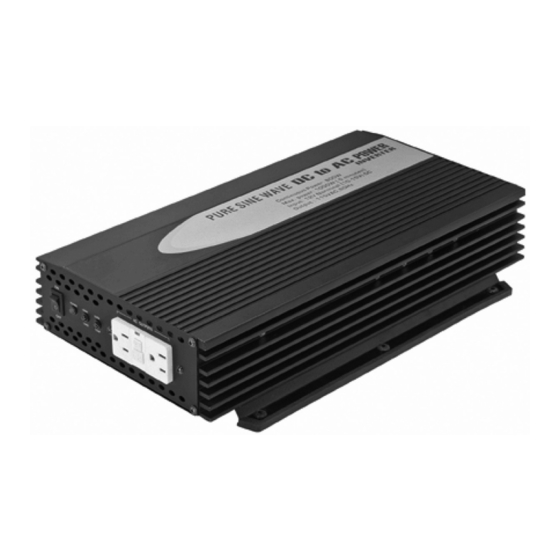
pOwer inverter with GFCi
set up and OperatinG instruCtiOns
distributed exclusively by Harbor Freight tools
visit our website at: http://www.harborfreight.com
read this material before using this product.
Failure to do so can result in serious injury.
save tHis manual.
©
Copyright
2009 by Harbor Freight Tools
or any artwork contained herein may be reproduced in any shape or form without the
express written consent of Harbor Freight Tools. Diagrams within this manual may not be
drawn proportionally. Due to continuing improvements, actual product may differ slightly
from the product described herein. Tools required for assembly and service may not be
included.
For technical questions or replacement parts, please call 1-800-444-3353.
800/1000 watt
pure sine wave
3491 Mission Oaks Blvd., Camarillo, CA 93011
66835
®
. All rights reserved. No portion of this manual
®
.
Advertisement
Table of Contents

Summary of Contents for Chicago Electric PURE SINE WAVE 66835
- Page 1 pure sine wave pOwer inverter with GFCi set up and OperatinG instruCtiOns distributed exclusively by Harbor Freight tools 3491 Mission Oaks Blvd., Camarillo, CA 93011 visit our website at: http://www.harborfreight.com read this material before using this product. Failure to do so can result in serious injury. save tHis manual.
-
Page 2: Important Safety Information
save tHis manual Keep this manual for the safety warnings and precautions, assembly, operating, inspection, maintenance and cleaning procedures. Write the product’s serial number in the back of the manual near the assembly diagram (or month and year of purchase if product has no number). Keep this manual and the receipt in a safe and dry place for future reference. - Page 3 replace the fuse in this item with another 25 amp fuse. Replac- ing the fuse with a higher rated fuse or another object is very dangerous and can result in fire, serious person- al injury, or death. Before every use, check for any broken parts or mounting fixtures, and any other condition that may affect proper operation.
-
Page 4: Specifications
cal known to the State of California to cause cancer and birth defects or other reproductive harm. (California Health & Safety Code § 25249.5, et seq.) People with pacemakers should consult their physician(s) before use. Electromagnetic fields in close proximity to a heart pacemaker could cause pacemaker interference or pacemaker failure. - Page 5 impOrtant saFetY inFOrmatiOn use caution when open- ing the plastic case; risk of electric shock. prevent body contact with grounded surfaces such as pipes, radiators, ranges, and re- frigerator enclosures during instal- lation. warninG! all connections must be done with the inverter’s power switch off.
- Page 6 ing point. The grounding point will vary depending on where the Power Inverter is installed. In a vehicle, connect the ground to the chassis of the vehicle. In a boat, connect to the boat’s grounding systems. If using a separate battery, not attached to a vehicle or boat, connect the ground to the earth.
-
Page 7: Maintenance
You should not use your car battery to power the Inverter for extended pe- riods of time with appliances requir- ing high continuous load levels. The battery may become drained to the point that it will not be able to start your car. -
Page 8: Troubleshooting Tips
If the alarm sounds, this means that the input voltage is at or below 10.6 V. The battery needs recharging. You should stop using the Power Inverter and recharge the battery. If this is not done, the Inverter will shut off automatically at 10 V. If you are unsure if the inverter will have the proper amount of current to run your devices, add up the total of the peak wattage of the items you wish to plug into the Inverter. -
Page 9: Parts List And Diagram
part description Housing Input Side Plate Terminal Support Positive Terminal Negative Terminal Grounding Terminal Fan Cover Side Fan PCB Module Trim record serial number Here: note: If product has no serial number, record month and year of purchase instead. note: Some parts are listed and shown for illustration purposes only, and are not avail- able individually as replacement parts. -
Page 10: Please Read The Following Carefully
please read tHe FOllOwinG CareFullY THE MANUFACTURER AND/OR DISTRIBUTOR HAS PROVIDED THE PARTS LIST AND ASSEMBLY DIAGRAM IN THIS MANUAL AS A REFERENCE TOOL ONLY. NEITHER THE MANUFACTURER OR DISTRIBUTOR MAKES ANY REPRESENTATION OR WARRANTY OF ANY KIND TO THE BUYER THAT HE OR SHE IS qUALIFIED TO MAKE ANY REPAIRS TO THE PRODUCT, OR THAT HE OR SHE IS qUALIFIED TO REPLACE ANY PARTS OF THE PRODUCT.


