Table of Contents
Advertisement
Quick Links
Advertisement
Table of Contents

Related Manuals for Teledyne Lecroy HDO4024A-MS


Summary of Contents for Teledyne Lecroy HDO4024A-MS
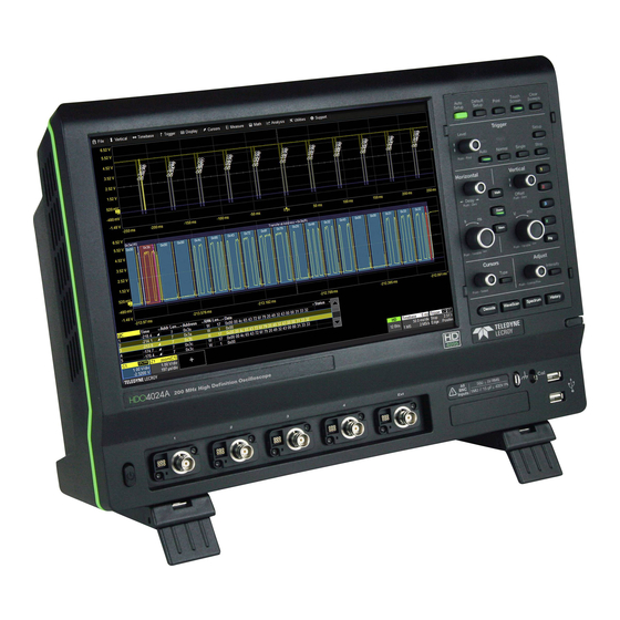
- Page 1 HDO4000A Oscilloscopes Getting Started Guide...
- Page 2 Teledyne LeCroy documentation for internal educational purposes. Teledyne LeCroy is a trademark of Teledyne LeCroy, Inc. Other product or brand names are trademarks or requested trademarks of their respective holders. Information in this publication supersedes all earlier versions. Specifications are subject to change without notice.
-
Page 3: Table Of Contents
Welcome Thank you for buying a Teledyne LeCroy product. We’re certain you’ll be pleased with the detailed features unique to our instruments. This guide is intended to help you set up a HDO4000A oscilloscope and learn some basic operating procedures, so you're quickly working with waveforms. -
Page 4: Introduction
INTRODUCTION Introducing HDO4000A Key Specifications Detailed specifications are on the product datasheet at teledynelecroy.com. Combining Teledyne LeCroy’s HD4096 high-definition technology with long memory, a compact form factor, 12.1” touch screen display, powerful Bandwidth 200 MHz to 1 GHz measurement and analysis tools, and mixed signal capability, the... - Page 5 SAFETY Operating Environment Precautions Use proper power cord. Use only the power cord shipped with this Temperature 5 °C to 40 °C instrument and certified for the country of use. Humidity Maximum RH 90% (non-condensing) up to 31 °C Maintain ground. The AC inlet ground is connected to the frame of the decreasing linearly to RH 50% at 40 °C instrument.
-
Page 6: Overview
OVERVIEW Front of Oscilloscope A. Touch Screen Display B. Front Panel C. Built-in Stylus Holder D. Power On/Standby Button E. Input Channels 1-4 F. EXT Input G. Mixed Signal Interface H. Ground and Cal Out Terminals I. USB Ports J. Rotating/Tilting Feet 929955-00 Rev A... -
Page 7: Powering On/Off
OVERVIEW Powering On/Off The touch screen display is the principal viewing and control center of Plug the line cord only into a grounded AC power outlet. See Power in the oscilloscope. See p.10 for an overview of its components. “Safety” for ratings. Press the Power button to turn on the oscilloscope. The button will light to show the oscilloscope is operational. -
Page 8: Back And Side Of Oscilloscope
OVERVIEW Side and Back of Oscilloscope A. HDMI and DisplayPort Ports C. Ethernet Ports (2) E. Built-in Carrying Handle G. REF In/Out B. USB 3.1 Gen 1 Ports (4) D. Audio Mic and Speaker F. AUX Out H. USBTMC Port for remote control I. -
Page 9: Connecting To External Devices/Systems
OVERVIEW Connecting to External Devices/Systems Remote Control You can control the instrument over a LAN using VICP (TCP/IP) or See the HDO4000A Oscilloscopes Operator’s Manual for more instructions VXI-11 (LXI). Use a standard ENET cable to connect to a network access on connecting to external devices. - Page 10 HDO4000A oscilloscopes are compatible with the included passive probes extenders and flying ground leads are available for different probing and most Teledyne LeCroy ProBus active probes that are rated for the needs. To achieve optimal signal integrity, connect the ground at the tip oscilloscope’s bandwidth.
-
Page 11: Front Panel
OVERVIEW Front Panel Most of the front panel controls duplicate functionality available through the touch screen display. They are covered in more detail in the Basics section and in the HDO4000A Oscilloscopes Operator’s Manual. Below are some special front panel controls. A. -
Page 12: Touch Screen Display
OVERVIEW Touch Screen Display The entire display is active. Use your finger or a stylus to touch, drag-and-drop, swipe, pinch and flick. Many controls that display information also work as “buttons” to access other functions. If you have a mouse installed, you can click anywhere you can touch to activate a control; in fact, you can alternate between clicking and touching, whichever is convenient for you. - Page 13 OVERVIEW A drop-down menu bar lets you access set up dialogs and other A toolbar along the bottom of the main Channel, Math, Memory and functions. All functionality can be accessed through either the menu bar Digital dialogs initiates frequent actions without closing the underlying or other touch screen shortcuts.
-
Page 14: Basics
BASICS Changing the Display The grid is 8 Vertical divisions representing 4096 Vertical levels and 10 By default, the oscilloscope has the Auto Grid Mode enabled. Auto adds a grid for each new trace, up to 16 grids, until no more grids are available. Horizontal time divisions. - Page 15 BASICS Line and Intensity The front panel Intensity button sets the Adjust knob to control the trace intensity The trace style can be set to a series of separate sample Points or a setting. continuous vector Line. Grid Intensity makes the grid lines dimmer or brighter relative to the trace. When more data is available than can actually be displayed, Trace Intensity helps to visualize significant events by applying an algorithm that dims less frequently occurring samples.
-
Page 16: Working With Traces
BASICS Working With Traces Adjusting Setups Trace Descriptor Boxes On setup dialogs, many entries can be made by selecting from the pop-up Channel (C1-C4), Zoom (Z1-Z8), Math (F1-F8), Memory (M1-M4) and menu that appears when you touch a control. Digital (Digital1-Digital4) descriptor boxes appear along the bottom of the grid when a trace is turned on. -
Page 17: Maui With Onetouch
BASICS MAUI with OneTouch Touch, drag, swipe, pinch and flick can be used to create and change setups with one touch. Just as you change the display by using the set up dialogs, you can change the setups by moving different display objects. Use the setup dialogs to refine OneTouch gestures to precise values. As you drag &... - Page 18 BASICS Copy Setups Change Source To copy the setup of one trace to another of the same type (e.g., channel to To change the source of a trace, drag-and-drop the descriptor box of the channel, math to math), drag-and-drop the source descriptor box onto the desired source onto the target descriptor box.
- Page 19 BASICS Position Cursors Change Trigger To change cursor measurement time/level, drag cursor markers to new To change the trigger level, drag the Trigger Level indicator to a new position positions on the grid. The cursor readout will update immediately. on the Y axis. The Trigger descriptor box will show the new voltage Level. To place horizontal cursors on zooms or other calculated traces where the Horizontal Scale has forced cursors off the grid, drag the cursor readout from below the Timebase descriptor to the grid where you wish to place the...
- Page 20 BASICS Store to Memory Scroll To store a trace to internal memory, drag-and-drop its trace descriptor box To scroll long lists of values or readout tables, swipe the selection dialog or onto the target memory (Mn) descriptor box. table in an up or down direction. Move Trace To move a trace to a different grid, drag-and-drop the trace descriptor box onto the target grid.
- Page 21 BASICS Zoom Turn Off To create a new zoom trace, touch then drag To turn off a trace, flick the trace descriptor box toward the bottom of diagonally to draw a selection box around the the screen. portion of the trace you want to zoom. Touch the Zn descriptor box to open the zoom factor controls and adjust the zoom exactly.
-
Page 22: Vertical (Channel)
BASICS Vertical (Channel) Vertical controls adjust traces along the Y axis. Traces represent eight Vertical divisions of the source signal at the selected number of units per division. The zero level is at the center grid line unless you add positive or negative Offset. The front panel Volts knob also controls the Vertical Scale of zoom, math and memory traces. - Page 23 BASICS From the Touch Screen Drop a channel descriptor on the Add New box, or touch the Add New box and choose Channel. Touch new Cn descriptor to open the Cn setup dialog. Enter Attenuation for passive and other vendors' probes. Enter Volts/div and Offset.
-
Page 24: Digital
BASICS Digital On Mixed Signal (-MS) instruments, Digital selections are added to the Vertical menu, and the front panel Vertical knobs control active Digital line and bus traces. From the Front Panel Digital Descriptor Box Turn Offset to # Digital Lines in Group raise/lower group Digital Sample Rate Vertical Position,... - Page 25 BASICS On the Logic Setup tab, choose a From the Touch Screen standard Logic Family, or enter a custom Threshold and Hysteresis. Separate controls allow you to set different values for each lead bank. From the menu bar, choose Vertical>Digital n Setup. Touch Digitaln descriptor to open Digitaln setup dialog.
-
Page 26: Horizontal (Timebase)
BASICS BASICS Horizontal (Timebase) Horizontal controls adjust traces along the X axis. Analog traces usually represent one acquisition of the source signal for 10 divisions of the selected Time per division. The trigger event is shown at the center of the grid, unless you add positive or negative Delay time. The front panel Time knob also controls the Horizontal Scale of zoom, math and memory traces, allowing you to "zoom in"... - Page 27 BASICS From the Touch Screen Touch the Timebase descriptor to open Enter Time/div. Timebase setup dialog. Select Sampling Mode. Optionally, enter Delay, Set To Zero Enter Maximum Points Reduce number of (negative) time before trigger removes Delay. of memory to use in Active Channels to or (positive) time after trigger acquisition.
-
Page 28: Triggers
BASICS Trigger Triggers tell the oscilloscope when to perform an acquisition. The acquisition starts as soon as the trigger is armed and all trigger conditions are met, unless postponed by a Holdoff count of time or number of trigger events. Trigger types and modes are described at more length in the HDO4000A Oscilloscopes Operator’s Manual. - Page 29 BASICS From the Touch Screen Touch Trigger descriptor to open Choose trigger Trigger setup dialog. Source channel. Choose trigger Type. Set trigger Level, Icon summarizes the Set other conditions, or Find Level based trigger selections. such as Slope and Coupling on the input signal.
-
Page 30: Zoom
BASICS Zoom Zoom traces (Zn) display a magnified portion of another trace. Any trace can be zoomed, although Zoom is most useful for channel traces, as it allows you to see the source at the original Timebase at the same time as the Zoom "close up." From the Front Panel When you use the front panel Zoom button, a new Zoom trace is created for every open trace, showing a 10x magnification of the source trace. - Page 31 BASICS From the Touch Screen Zoom descriptor opens Zoom dialog to make other adjustments. Draw a Zoom box over a portion of the source trace. Repeat on another section to reposition the Zoom trace. On the source trace setup dialog, touch Action Toolbar Zoom button to create a new zoom of just that source trace.
-
Page 32: Cursors
BASICS Cursors Cursors set measurement points on the Vertical or Horizontal axis of a trace (or both). The five preset cursor types are described in more detail in the HDO4000A Oscilloscopes Operator’s Manual. All show the absolute value where the cursor intersects the waveform and the delta of the two lines. From the Front Panel Adjust cursor position. -
Page 33: Measurements & Statistics
BASICS Measurements and Statistics Measurements are waveform parameters that can be expressed as numerical values, such as amplitude or frequency. You can measure up-to-eight parameters on one or more traces and view the active readout in a table below the grid. Statistics can be added to the readout, along with histicons, a miniature histogram of the statistical distribution. -
Page 34: Math
BASICS Math Math creates a new trace that displays the result of applying a mathematical function (e.g., Sum, Product, FFT) to one or more source traces. Operations can be chained by using one math function as a source for the other. The math trace always opens in a separate grid from the source and can be viewed along side it. -
Page 35: Memories (Reference Waveforms)
BASICS Memories (Reference Waveforms) Memories are traces stored for reference. They can be recalled to the display for comparison with other traces. A memory can be zoomed or measured for better analysis of historical data. You can store up-to-four internal memories (M1-M4). After that, new memories will overwrite previously stored data. To store a new memory: To recall a stored memory: Press the front panel Mem(ory) button to open the Memories dialog, then... -
Page 36: Decode
BASICS Decode The Decode front panel button opens the dialogs for configuring serial trigger and decode options. Decoders apply software algorithms to extract encoded information from physical layer waveforms measured on your oscilloscope. Waveforms are annotated to provide fast, intuitive understanding of the relationship between protocol and signal. -
Page 37: Wavescan
BASICS WaveScan Press the WaveScan front panel button to open the WaveScan dialogs. WaveScan Search and Find enables you to search for unusual events in a single capture, or to scan for a particular event in many acquisitions over a long period of time. A predefined set of scan modes (similar to trigger setups) enable a quick search for events of interest. -
Page 38: Spectrum Analyzer
BASICS Spectrum Analyzer If the Spectrum Analyzer option is installed, use the Spectrum front panel button to launch it. Spectrum Analyzer lets you quickly and easily use the Fast Fourier Transform (FFT) for frequency analysis. The controls are the same as you would find on an RF spectrum analyzer. You set the inputs and desired frequency span, and the oscilloscope automatically generates output in units relevant to the frequency domain. -
Page 39: History Mode
BASICS History Mode The History front panel button puts the instrument into History Mode, allowing you to review any acquisition in the oscilloscope’s history buffer, which automatically stores all acquisitions until full. Each record is indexed and time-stamped with either the absolute time since the beginning of history or the time relative to where you are in the history. -
Page 40: Saving And Sharing Data
BASICS Saving and Sharing Data Setup, Waveform and Table Data Use the oscilloscope File menu options to save and recall data. See the HDO4000A Oscilloscopes Operator’s Manual for more information on using The current oscilloscope configuration can be saved to internal setup these features. -
Page 41: Software Options
To install the key on the oscilloscope: Help for a demonstration of MAUI with OneTouch. 1. From the menu bar, choose Utilities > Utilities Setup > Options. Teledyne LeCroy publishes a free Technical Library on its website at teledynelecroy.com/support/techlib. Manuals, tutorials, application 2. Touch Add Key. -
Page 42: Cleaning
MAINTENANCE Cleaning Calibration Clean the outside of the oscilloscope using a soft cloth moistened The HDO4000A is calibrated at the factory prior to being shipped. This with water or isopropyl alcohol solution. Do not use harsh or abrasive calibration is run at 23° C (± 2° C) and is valid for temperatures ± 5° C of cleansers. -
Page 43: Firmware Updates
MAINTENANCE Firmware Updates Switching Windows Users Free firmware updates are available periodically from the Teledyne LeCroy Windows 10 oscilloscopes only. website at teledynelecroy.com/support/softwaredownload. Registered Windows 10 oscilloscopes are by default set to operate from the LeCroyUser users will receive email notification when a new update is released. -
Page 44: Service
Service Centers COD or Collect shipments. We recommend air freighting. Insure the item For a complete list of Teledyne LeCroy offices by country, including our you’re returning for at least the replacement cost. Follow these steps for a sales and distribution partners, visit: teledynelecroy.com/support/contact smooth product return. -
Page 45: Reference
MERCHANTABILITY, FITNESS, OR ADEQUACY FOR ANY PARTICULAR PURPOSE OR is not relevant to measuring, analyzing or documenting waveforms. USE. TELEDYNE LECROY SHALL NOT BE LIABLE FOR ANY SPECIAL, INCIDENTAL, OR CONSEQUENTIAL DAMAGES, WHETHER IN CONTRACT OR OTHERWISE. THE CUSTOMER IS RESPONSIBLE FOR THE TRANSPORTATION AND INSURANCE CHARGES FOR THE RETURN OF PRODUCTS TO THE SERVICE FACILITY. -
Page 46: Certifications
Certifications 2 Emissions which exceed the levels required by this standard may occur when the instrument is Teledyne LeCroy certifies compliance to the following standards as of connected to a test object. the time of publication. Please see the EC Declaration of Conformity 3 This product is intended for use in nonresidential areas only. - Page 47 (socket For more information about proper disposal and recycling of your outlets and similar). Teledyne LeCroy product, please visit teledynelecroy.com/recycle. • Measuring Circuit Terminals: No rated measurement category. Terminals not intended to be connected directly to the mains supply.
- Page 48 929955-00 Rev A, January, 2019 © 2019 Teledyne LeCroy, Inc. All rights reserved.