
Related Manuals for Teledyne Lecroy CP030


Summary of Contents for Teledyne Lecroy CP030
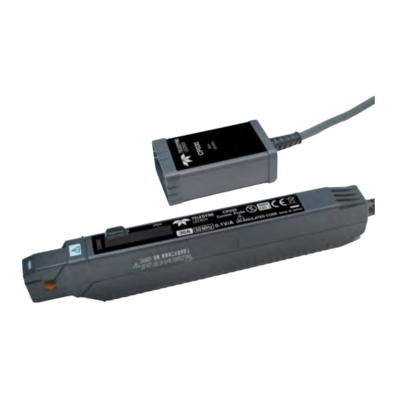
- Page 1 Instruction Manual CP030 Current Probe 1.888.610.7664 www.calcert.com sales@calcert.com...
- Page 2 CP030 Current Probe Instruction Manual January 2013 1.888.610.7664 www.calcert.com sales@calcert.com...
- Page 3 Spare parts, replacement parts and repairs are warranted for 90 days. In exercising its warranty, Teledyne Lecroy, at its option, will either repair or replace any assembly returned within its warranty period to the Customer Service Department or an authorized service center. However, this will be done only if the product is determined by Teledyne Lecroy’s examination to be defective due to workmanship or...
-
Page 4: Table Of Contents
Precautions ................................4 Connecting the Probe to the Test Instrument ......................4 Connecting the Probe to the Test Circuit ........................4 Operation with a Teledyne LeCroy Oscilloscope ...................... 5 Bandwidth Limit ................................. 5 Auto Zero .................................. 5 Degauss Probe ................................. 5 Care and Maintenance ..............................6... - Page 5 End-Of-Life Handling ............................18 Restriction of Hazardous Substances (RoHS) ....................18 Contact Teledyne LeCroy ............................. 19 Appendix A ................................... 20 Performance Verification Test Record ........................20 Equipment Used ..............................20 CP030 Test Record ..............................20 922173-00 Rev A 1.888.610.7664 www.calcert.com sales@calcert.com...
-
Page 6: Safety Instructions
Instruction Manual Safety Instructions This section contains instructions that must be observed to keep this oscilloscope accessory operating in a correct and safe condition. You are required to follow generally accepted safety procedures in addition to the precautions specified in this section. The overall safety of any system incorporating this accessory is the responsibility of the assembler of the system. -
Page 7: Operating Environment
CP030 Current Probe Never install or remove the probe on bare conductors which are energized. The transformer core and shield are grounded but not insulated and may contact the conductor when the locking lever is open. To avoid short circuits and accidents that could result in injury or death, use the CP031 current probe only with conductors carrying 300 V or less. -
Page 8: Overview
The probe can be used with a WaveSurfer, WaveRunner 6000, or WavePro 7000 series oscilloscope with firmware 4.3.0.0 or higher. With the ProBus interface, the CP030 becomes an integral part of the oscilloscope. The bandwidth limit, auto zero and degauss functions are all controlled from the oscilloscope’s graphical user interface. -
Page 9: Operation
To use the CP030 with a WaveMaster scope, the AP-1M impedance adapter is required. Connecting the Probe to the Test Circuit The CP030 has been designed with a movable split core, eliminating the need to break the conductor for the core to slip around the conductor. -
Page 10: Operation With A Teledyne Lecroy Oscilloscope
Turning the VOLTS/DIV knob will control the oscilloscope’s scale factor to give full dynamic range from 20 mA/div to 50 A/div. The CP030 probe dialog (a tab behind the channel setup dialog) allows for the selection of the probe’s coupling (DC, Grounded or AC), AUTO ZERO, DEGAUSS PROBE and Probe BWL functions, limiting the system bandwidth to 20 MHz or maximum bandwidth (BWL Off). -
Page 11: Care And Maintenance
(A Performance Verification / Adjustment procedure is included in this manual.) Service Strategy Defective probes must be returned to a Teledyne Lecroy service facility for diagnosis and exchange. A defective probe under warranty will be replaced with a factory refurbished probe. A probe that is not under warranty can be exchanged for a factory refurbished probe. -
Page 12: Returning A Defective Probe
5. Package the probe case in a cardboard shipping box with adequate padding to avoid damage in transit. 6. Mark the outside of the box with the shipping address given to you by the Teledyne Lecroy representative; be sure to add the following: •... -
Page 13: Performance Verification
CP030 Current Probe Performance Verification This procedure can be used to verify the warranted characteristics of the CP030 Current Probe. The recommended calibration interval for the model CP030 Current Probe is one year. The complete performance verification procedure should be performed as the first step of annual calibration. -
Page 14: Preliminary Procedure
1. Connect the CP030 to the channel 1 input of the oscilloscope and completely close the probe slider. 2. Turn the oscilloscope on and allow at least 30 minutes warmup time for the CP030 and test equipment before performing the Verification Procedure. -
Page 15: Check Lf Accuracy
6. With the CP030 removed from any signal and the slider returned to the LOCKED position, degauss the probe by pressing the DEGAUSS button (located in the CP030 dialog), then OK. 7. Open the CP030 slider and position the probe input around the 100 Turn loop. Close and LOCK the slider. -
Page 16: Adjustment Procedure
Instruction Manual Adjustment Procedure This procedure can be used to adjust the warranted characteristics of the CP030 Current Probe. This procedure should be used if a parameter measured in the Performance Verification Procedure is outside of the specification limits. Adjustment should only be performed by qualified personnel. -
Page 17: Preliminary Procedure
2. Connect the CP030 compensation board to the channel 1 input of the oscilloscope through the ProBUS extension cable, and completely close the probe slider. 3. Turn the oscilloscope on and allow at least 30 minutes warmup time for the CP030 and test equipment before performing the Verification Procedure. - Page 18 DEGAUSS button on the oscilloscope, (located in the CP030 dialog), then pressing OK. 7. Open the CP030 slider and position the probe input around the 100 Turn loop. Close and LOCK the slider. 8. Adjust the Function Generator voltage until the voltage measured at the 'Current Sense' terminals (DMM #2) is 50 mV ±...
-
Page 19: Specifications
CP030 Current Probe Specifications Nominal Characteristics Nominal characteristics describe parameters and attributes which are guaranteed by design, but do not have associated tolerances. Maximum Continuous Input Current 30 A (Refer to Figure 3) Maximum Peak Current 50 A , noncontinuous... -
Page 20: Environmental Characteristics
Instruction Manual Environmental Characteristics Operating Temperature Humidity 0 to 40 °C (32 °F to 104 °F) ≤80% relative humidity (non-condensing) Storage Temperature Humidity –10 °C to 50 °C (14 °F to 122 °F) ≤80% relative humidity (non-condensing) Usage Indoor Altitude up to 2000 m (6562 feet) Effect of External Magnetic Equivalent to a maximum of... -
Page 21: Graphs
CP030 Current Probe Graphs Figure 3. Maximum input current vs. frequency. Frequency (Hz) Figure 4. Insertion impedance vs. frequency. 922173-00 Rev A 1.888.610.7664 www.calcert.com sales@calcert.com... -
Page 22: Certifications
3 Meets Performance Criteria “B” limits of the respective standard: during the disturbance, product undergoes a temporary degradation or loss of function or performance which is self-recoverable. UROPEAN ONTACT Teledyne LeCroy Europe GmbH Waldhofer Str 104 D-69123 Heidelberg Germany Tel: (49) 6221 82700 Australia &... -
Page 23: Safety Compliance
CP030 Current Probe CISPR 11:2003 Radiated and Conducted Emissions, Group 1, Class A, in accordance with EN61326-1:2006 and EN61326-2-1:2006. USTRALIA EALAND ONTACTS Vicom Australia Ltd. Vicom New Zealand Ltd. 1064 Centre Road 60 Grafton Road Oakleigh, South Victoria 3167 Auckland... -
Page 24: Contact Teledyne Lecroy
Performance Verification Test Record Photocopy this page and record the results of measurements made during the performance verification of the CP030 Current Probe on the copy. File the completed record as required by applicable internal quality procedures. The sections in the test record correspond to the parameters tested in the performance verification procedure.