Table of Contents
Advertisement
Quick Links
Advertisement
Table of Contents

Related Manuals for Behringer ULTRALINK ULB2000


Summary of Contents for Behringer ULTRALINK ULB2000
- Page 1 User’s manual Version 1.0 August 2006...
- Page 2 ULTRALINK ULB2000 IMPORTANT SAFETY INSTRUCTIONS CAUTION: To reduce the risk of electric shock, do not remove the top cover (or the rear section). No user serviceable parts inside; refer servicing to qualified personnel. This symbol, wherever it appears, WARNING: To reduce the risk of fire or electric...
-
Page 3: Table Of Contents
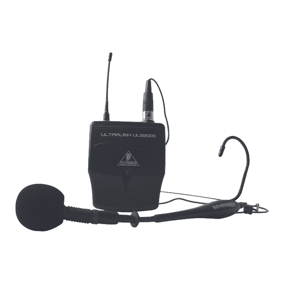
MICROPHONE QUICK START GUIDE ................16 1. INTRODUCTION Thank you very much for expressing your confidence in us by purchasing the ULTRALINK ULB2000. This Transmitter, coupled to the receiver ULR2000 from BEHRINGER, comprises a modern, high- performance wireless transmission system. -
Page 4: Before You Get Started
Determining which microphone is assigned to which receiver is done either by observing the transmission channel in the display or by comparing the transmission frequency. In addition, the ULTRALINK equipment from BEHRINGER leaves you the option to color-code your gear for easy identification. -
Page 5: Online Registration
To arrange for warranty service, please contact the retailer from whom the equipment was purchased. Should your BEHRINGER dealer not be located in your vicinity, you may directly contact one of our subsidiaries. Corresponding contact information is included in the original equipment packaging (Global Contact Information/European Contact Information). -
Page 6: Operating The Transmitter
ULTRALINK ULB2000 3. OPERATING THE TRANSMITTER A brief overview with the graphic representation on operating the transmitter is found on the last page of this user manual (QUICK REFERENCE GUIDE). 3.1 Turning the transmitter on Press the transmitter's POWER button for 2 seconds. -
Page 7: Preset
ULTRALINK ULB2000 Enter all 6 digits one after another in the following fashion: Select the desired value on the selection switch, for example 4. If a valid value is selected, the LED blinks quickly once as a confirmation. This way, you can be sure that a correct value is entered (in regard to the frequency range and divisibility by 25 kHz) even before confirming your selection. -
Page 8: Mic Gain
ULTRALINK ULB2000 CHANNEL PRESET 2 PRESET 3 PRESET 4 798,700 MHz 798,400 MHz 798,100 MHz 799,950 MHz 798,950 MHz 798,650 MHz 800,650 MHz 799,800 MHz 799,500 MHz 801,050 MHz 801,450 MHz 801,150 MHz 802,850 MHz 803,250 MHz 802,950 MHz 804,500 MHz... -
Page 9: Auto Mute
ULTRALINK ULB2000 Turn the selection switch to 0 and confirm your selection by keeping the POWER button pressed for 2 seconds. As a confirmation, the LED blinks slowly once and then once again with medium tempo. The transmitter is now in the programming mode and waits for you to enter a one-digit number. -
Page 10: Turning The Transmitter Off
ULTRALINK ULB2000 Select one of the following two digits on the selection switch: Activate Auto Mute: select 7 Deactivate Auto Mute: select 8 If a valid selection is made, the LED blinks quickly once to confirm your selection. This way, you can be sure that a correct value is entered (in regard to preset, MicGain and Auto Mute selection) even before confirming your selection. -
Page 11: Transmission Frequency
ULTRALINK ULB2000 4.2 Transmission frequency Turn the selection switch to 9. The position of the MUTE switch is irrelevant. Briefly press the POWER button. Just like during programming, 6 blink medium-tempo codes indicate the individual digits that make up the transmission frequency. Individual codes are separated from one another by brief pauses. -
Page 12: Application Example
ULTRALINK ULB2000 6. APPLICATION EXAMPLE Fig. 6.1 shows how easy it is to use the ULB2000. Simply connect the receiver ULR2000 to your mixing console. Fig.6.1: Wiring the ULR2000 receiver and the ULB2000 microphone 7. INSTALLATION 7.1 Operating information The quality of the wireless transmission depends on various local factors as well as the degree of radiation and reception at transmitter and receiver, unlike the signal transmission over cable. -
Page 13: Audio Connections
ULTRALINK ULB2000 The devices should always be at a height of at least 1 m (3 ft.) off the ground. To assure interference-free reception, ideally there should be no large objects placed between the transmitter and the receiver. Not only the size but also the type of material play a role in... -
Page 14: Specifications
Their use neither constitutes a claim of the trademarks by BEHRINGER nor affiliation of the trademark owners with BEHRINGER. BEHRINGER accepts no liability for any loss which may be suffered by any person who relies either wholly or in part upon any description, photograph or statement contained herein. -
Page 15: Federal Communications Commission Compliance Information
Notice: Changes or modifications made to this equipment not expressly approved by BEHRINGER International GmbH may void the FCC/ IC authorization to operate this equipment. FEDERAL COMMUNICATIONS COMMISSION COMPLIANCE INFORMATION... -
Page 16: Microphone Quick Start Guide
ULTRALINK ULB2000 MICROPHONE QUICK START GUIDE MICROPHONE QUICK START GUIDE...