Advertisement
Quick Links
Die deutschsprachige Version kann von
heruntergeladen werden.
Vous pouvez télécharger la version française sur www.vaisala.com/PDT101.
www.vaisala.com/PDT101
日本語版は
www.vaisala.com/PDT101
您可以访问
WARNING - READ BEFORE INSTALLATION
Vaisala Differential Pressure Transmitter PDT101 is a high-performance
instrument designed primarily for use in life science and cleanroom
applications. PDT101 is not authorized for use as a critical component in life
support devices or systems. Consult Vaisala before installing if there are any
questions or concerns.
Overpressure: Pressure spikes in excess of the rated overpressure capability
of the transmitter may cause irreversible electrical and/or mechanical damage
to the transmitter.
Static electrical charges: To avoid damage to the transmitter the
operator/installer should follow proper ESD (electrostatic discharge)
protection procedures.
TECHNICAL SPECIFICATION
Performance
Measurement range (bidirectional)
Overpressure
Proof pressure
Burst pressure
Static pressure
Pressure type
Accuracy
(incl. non-linearity, hysteresis,
repeatability and zero/span
calibration settings)
Long-term stability
Response time (10...90 %)
Warm-up time
Compensated temperature range
Temperature dependence
Mounting position error
(zero adjustable)
Adjustments (front accessible)
Zero
Span
Operating environment
Operating temperature
Storage temperature
Electromagnetic compatibility
Note: If used in an electromagnetic field of 3 V/m, with narrow frequency area
of 80 - 120 Mhz, it is possible that the current output of PDT101 can deviate
max. 0.8% (with accuracy specified 0.4%).
Inputs and outputs
Process connection
Output signal
2-wire
3-wire
Operating voltage
2-wire output 4...20 mA
3-wire output 0...5 VDC
3-wire output 0...10 VDC
M211284EN-E ___________________________________________________________________________________ 1
Vaisala Differential Pressure Transmitter
www.vaisala.com/PDT101
からダウンロードできます。
下载简体中文翻译。
±60 Pa
or ±0.25 in H
1.0 bar
1.7 bar
1.7 bar
Differential, gauge,
vacuum and compound
0.4 % span
≤0.5 % span/year
250 ms
+2...+54 °C
(+35.6...+129.2 °F)
±(0.065 Pa + 0.054 % of reading) / °C
±(0.00015 inH
O + 0.03 % of reading) / °F
2
(reference 21 °C or 70 °F)
≤1 %/g (calibration in vertical
position is standard)
±5 % span
±3 % span
-18...+70 °C (-0.4...+158 °F)
-40...+82 °C (-40...+179.6 °F)
EN61326-1, Basic immunity
test requirements
1/4" barbed fittings
4...20 mA
0...5 VDC
(user selectable 0...10 VDC)
12...36 VDC
11.5...36 VDC
14...36 VDC
or 24 VAC
Max. loop resistance for 4...20 mA
Supply current
Optical process diagnostics
Electrical connection
Mechanics
Medium (measured gas)
Material
Mounting
Housing classification
Weight
MOUNTING
The transmitter can be mounted on an EN550022 rail or with M4 (#8) or
M5 (#10) screws using the mounting holes provided.
37
ø
5
O
2
POWER
HI
ZERO
ø
4
15 s
48
Figure 1 Dimensions (in mm)
or
Zero adjust
potentiometer
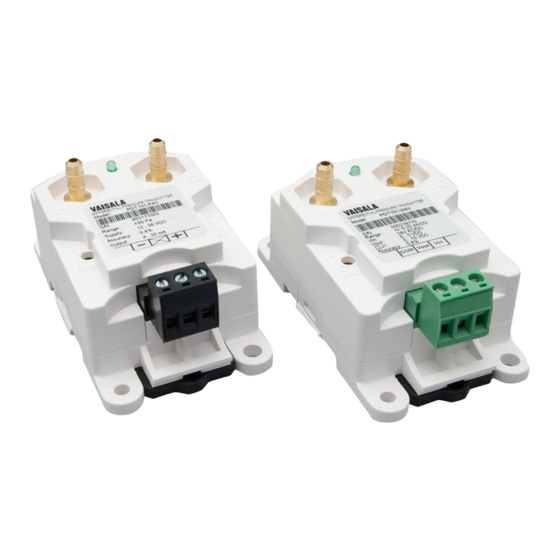
Figure 2 PDT101 Transmitter
PDT101
≤ (Supply voltage - 12V)/0.022 A
max. 20 mA for 4...20 mA output signal
LED visual indicator
Euro style pluggable terminal block accepts
12...26 AWG wire (0.13 up to 3.31 mm
Clean and dry air, non-conducting and
non-corrosive gases
Process connection
Sensor element
Silicon, aluminum, glass
Case
NEMA type 1 fire-retardant ABS 1
(meets UL94-5VA)
Threaded fastener for wall mounting
or DIN rail type EN50022
LO
74 84.6
SPAN
Power LED
POW ER
HI
LO
Span adjust
potentiometer
ZER O
S PAN
Terminal block
2
)
Brass
IP40
0.07 kg
9.4
33.6
Advertisement

Related Manuals for Vaisala PDT101


Summary of Contents for Vaisala PDT101
- Page 1 Note: If used in an electromagnetic field of 3 V/m, with narrow frequency area of 80 - 120 Mhz, it is possible that the current output of PDT101 can deviate ZER O S PAN max. 0.8% (with accuracy specified 0.4%).
- Page 2 1. Remove the terminal block on the front of the transmitter. – Common (V-) Vin (V+, Supply) 2. Follow the terminal block label markings on the PDT101 to identify the Power Supply terminals, and connect the wires. 3. Firmly reinstall the terminal block plug to its mating connector.