Table of Contents
Advertisement
Quick Links
Advertisement
Table of Contents

Related Manuals for Strongway 46271


Summary of Contents for Strongway 46271
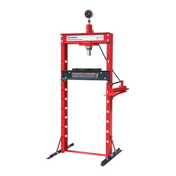
- Page 1 20-TON HYDRAULIC SHOP PRESS OWNER’S MANUAL WARNING: Read carefully and understand all ASSEMBLY AND OPERATION INSTRUCTIONS before operating. Failure to follow the safety rules and other basic safety precautions may result in serious personal injury. Item# 46271...
-
Page 2: Intended Use
Thank you very much for choosing a Strongway product! For future reference, please complete the owner’s record below: Model: _______________ Purchase Date: _______________ Save the receipt, warranty and these instructions. It is important that you read the entire manual to become familiar with this product before you begin using it. -
Page 3: General Safety Rules
GENERAL SAFETY RULES WARNING: Read and understand all instructions. Failure to follow all instructions listed below may result in serious injury. CAUTION: Do not allow persons to operate or assemble this Jack until they have read this manual and have developed a thorough understanding of how the Jack works. WARNING: The warnings, cautions, and instructions discussed in this instruction manual cannot cover all possible conditions or situations that could occur. -
Page 4: Safety Markings
DO NOT OPERATE OR REPAIR THIS EQUIPMENT WITHOUT READING THIS MANUAL. To maintain the Shop Press and user safety, the responsibility of the owner is to read and follow these instructions. Inspect the service shop press for proper operation and function. Keep instructions readily available for equipment operators. - Page 5 PLEASE READ THESE INSTRUCTIONS CAREFULLY.NOTE SAFETY INSTRUCTIONS WARNING.USE THE PRODUCT CORRECTLY AND WITH CARE FOR THE PURPOSE OF WHICH IT IS INTENDED.FAILURE TO DO SO MAY CAUSE DAMAGE TO PROPERTY AND/OR SERIOUS PERSONAL INJURY. PLEASE KEEP THIS INSTRUCTION MANUAL SAFE FOR FUTURE USE. We’ve done all we can to assure this press offers the utmost in safety, but you have to do your part.
- Page 6 ASSEMBLY Use the exploded drawing as your guide to assembly. Lay all parts and assemblies out in front of you before beginning. The following procedure is recommended: All numbers in parenthesis () refer to the index number from the parts breakdown. Use caution as parts may be heavy in weight and can cause pinch points to hands, body and feet.
- Page 7 3. Put the press frame in the upright position, attach one upper cross beam (29) to left and right frame (12) using bolts (25), washer (26).lock washer (27) and nuts (28). 4. Put the opposing upper crossbeam (29) into position and insert the cylinder support plate (24) below the two upper cross beams at the same time, then secure this cross beam to the frame using bolts (25), washers (26).lock washers (27) and nuts (28).
- Page 8 5. Insert the hydraulic cylinder (31) from the top side of frame. Once the cylinder is inserted into the frame support plate (24) make sure that the round lifting ring (40) is seated flat on the cylinder support plate (24). Then attach the round threaded nut (41) to the hydraulic cylinder. Turn clockwise to screw the round nut onto threaded shaft on the ram.
- Page 9 7. Attach the pump assembly plate(18) to the right frame using bolts (19), washers (09), lock washers (10) and nuts (11), then secure the pump assembly using screws (16) and washer (17). When this step is complete insert the handle to the handle bracket. 8.
- Page 10 SYSTEM AIR PURGE PROCEDURE Perform the following Air Purge Procedure to remove any air that may have been introduced into the hydraulic system as a result of product shipment and handing. This step is to be completed without and weight on the shop press. 1.
-
Page 11: Before Use
BEFORE USE 1. Before using this product, read the owner's manual completely and familiarize yourself thoroughly with the product and the hazards associated with its improper use. 2. Perform the air purge procedure. (See previous instructions for system purge procedure.) 3. - Page 12 5. Pump the handle until ram nears work piece. Align work piece and ram to ensure center-loading. Pump the handle to apply load onto work piece. 6. Align ram and work piece to ensure center loading. 7. When work is completed, stop pumping the handle. Slowly turn the release valve counter-clockwise in small increments until ram is free from work piece.
-
Page 13: Maintenance Instructions
MAINTENANCE INSTRUCTIONS If you use and maintain your equipment properly, it will give you many years of service. Follow the maintenance instructions carefully to keep your equipment in good working condition. Never perform any maintenance on the equipment while it is under a load. Inspection You should inspect the product for damage, wear, broken or missing parts (e.g.: pins) and that all components function before each use. - Page 14 To Add Oil: 1. Set Pump Unit upright on a level surface. 2. Remove the Screw with its attached dipstick. 3. Add 0.22 quarts (about 7.43oz., or 770ml) of oil. The oil level should be near Position (A). Use a high grade anti-foaming hydraulic oil. KEEP DIRT AND OTHER MATERIALS CLEAR WHEN POURING.
- Page 15 Replace the Oil Fill Screw. 4. Perform the Air Purge Procedure. To Replace Oil: 1. Set Pump Unit upright on a level surface. 2. Remove the screw with its attached dipstick .
- Page 16 3. Turn the Pump Unit on its side so that old oil will drain from the oil fill hole. 4. Set Pump Unit upright on a level surface. 5. Add 0.22 quarts (about 7.43oz., or 770ml) of oil. The oil level should be near Position (A). Use a high grade anti-foaming hydraulic oil.
- Page 17 6. Replace the Oil Fill Screw. 7. Perform the Air Purge Procedure. ADDITIONAL WARNINGS: DO NOT USE MOTOR OIL IN THE JACK. ONLY USE ANTI-FOAMING JACK OIL. ALWAYS USE A GOOD GRADE HYDRAULIC JACK OIL. DO NOT USE HYDRAULIC BRAKE FLUID, ALCOHOL, GLYCERINE, DETERGENT, MOTOR OIL OR DIRTY OIL.
- Page 18 3. Periodically check the pump piston and ram for signs of rust or corrosion. Clean as needed and wipe with a soft non-abrasive clean cloth. 4. A coating of light lubricating oil to pivot points. Axles and hinges will help to prevent rust. When not in use, store the press in a dry location with ram and pump piston fully retracted.
-
Page 19: Assembly Diagram
ASSEMBLY DIAGRAM... -
Page 20: Assembly Parts List
ASSEMBLY PARTS LIST Index # Description Part No. Qty. Base Supports Sections TY20001-07 Nuts Bolt M10x25 GB5783 Nuts Bolt M12x35 GB5782 Side Support Rails TY12002-02 Nuts Bolt M10x30 GB5783 Washer 10 GB97.1 Spring washer 10 GB93 Nuts M10 GB6170 Washer 12 GB97.1 Spring washer 12 GB93... - Page 21 RAM ASSEMBLY DIAGRAM...
- Page 22 RAM PARTS LIST Index # Description Part No. Qty. Dust cap QF4-34 Coupler and Connection Nut QF4.6 Restructuring Bolt M8X30 TY20001Q.1-01 Cylinder TY20001Q.1.1 Round Threaded Nut TY20001.1-05 Round Lifting Ring TY20001.1-04 Nut M8 GB6170 Spring TY20001Q.1.2 Protecting cap TY20001.1-01 Bolt M8X12 GB70-85 Rectangle ring QLZ2C.6-17A...
-
Page 23: Pump Assembly Diagram
PUMP ASSEMBLY DIAGRAM... -
Page 24: Pump Assembly Parts List
PUMP ASSEMBLY PARTS LIST Index # Description Part No. Qty. Base TY12001.2-04 Filter QF4-16 Seal QF4-9 Reservoir TY20005.1-01 Top Nut QF4-10 Pump Foot TY12001.2.5 Nut M18 GB6172-86 O-Ring 7.7X1.9 QLQ2.1-17 Dipstick QF4.1 Ball Φ5 GB308-84 Ball Φ8 GB308-84 Spring QF4-13 Screw M10X1 QF4-12 Release Valve Stem... -
Page 25: Troubleshooting
TROUBLESHOOTING WILL WILL WILL NOT POOR WILL NOT CAUSES AND SOLUTIONS RETRACT LIFTING LIFT TO LIFT HOLD FULL LOAD LOAD EXTENSION Release valve is not completely closed (Turn handle clockwise). Weight Capacity Exceeded. - Page 26 Northern Tool and Equipment Company, Inc. ("We'' or '"Us'') warrants to the original purchaser only ("You'' or “Your”) that the Strongway product purchased will be free from material defects in both materials and workmanship, normal wear and tear excepted, for a period of one year from date of purchase.