
Related Manuals for Ricoh Lily


Summary of Contents for Ricoh Lily
- Page 1 Aficio Color 5106/5206 (Lily, A172/A199) Service Manual Issued May 10, 1996, Ricoh CO., LTD.
- Page 2 PARTS CATALOG First Edition June 1996 Ricoh Company,LTD.
- Page 3 PARTS CATALOG INTRODUCTION This chapter instructs you the numbers and names of parts on this machine. INDEX to PARTS CATALOG Lily (Copier) (A172/A199) DF62 (A610) CS250 (A322) Sorter Adapter Type J (A527) SPU3 (A718) Holder Type C (A702)
-
Page 5: Table Of Contents
PARTS CATALOG INTRODUCTION This chapter instructs you the numbers and names of parts on this machine. INDEX to PARTS CATALOG Location of Unit ..............3 19.Around The Drum (A172/A199)........48 1.Exterior 1 (A172/A199) ............. 12 20.Drum Unit 1 (A172/A199) ..........50 2.Exterior 2 (A172/A199) ............. - Page 6 38.Drive Section 1 (A172/A199) ........... 86 39.Drive Section 2 (A172/A199) ........... 88 40.Drive Section 3 (A172/A199) ........... 90 41.Drive Section 4 (A172/A199) ........... 92 42.Electrical Section 1 (A172/A199)........94 43.Electrical Section 2 (A172/A199)........96 44.Electrical Section 3 (A172/A199)........98 45.Electrical Section 4 (A172/A199)........100 46.Frame Section 1 (A172/A199) .........
-
Page 7: Location Of Unit
Location of Unit 1. Exterior 1 (A172/A199) 2. Exterior 2 (A172/A199) 3. Operation Panel (A172/A199) See Page 12 See Page 14 See Page 16 4. Optics Section 1 (A172/A199) 5. Optics Section 2 (A172/A199) 6. Optics Section 3 (A172/A199) See Page 18 See Page 20 See Page 22... - Page 8 Location of Unit 7. Optics Section 4 (A172/A199) 8. Printer Section 1 (A172/A199) 9. Printer Section 2 (A172/A199) See Page 24 See Page 26 See Page 28 10. 1st And 2nd Paper Feed Tray (A172/A199) 11. 3rd Paper Feed Tray (A172/A199) 12.
- Page 9 Location of Unit 13. Paper Supply Unit 2 (A172/A199) 14. Paper Supply Unit 3 (A172/A199) 15. Paper Feed Section 1 (A172/A199) See Page 36 See Page 38 See Page 40 16. Paper Feed Section 2 (A172/A199) 17. By-pass Feed Table (A172/A199) 18.
- Page 10 Location of Unit 19. Around The Drum (A172/A199) 20. Drum Unit 1 (A172/A199) 21. Drum Unit 2 (A172/A199) See Page 48 See Page 50 See Page 52 22. Toner Tank Unit 1 (A172/A199) 23. Toner Tank Unit 2 (A172/A199) 24. Development Unit - Black (A172/A199) See Page 54 See Page 56 See Page 58...
- Page 11 Location of Unit 25. Development Unit - Cyan (A172/A199) 26. Development Unit - Magenta (A172/A199) 27. Development Unit - Yellow (A172/A199) See Page 60 See Page 62 See Page 64 28. Transfer Belt Unit 1 (A172/A199) 29. Transfer Belt Unit 2 (A172/A199) 30.
- Page 12 Location of Unit 31. Transport Unit (A172/A199) 32. Belt Cleaning Unit (A172/A199) 33. Toner Collection Section (A172/A199) See Page 72 See Page 74 See Page 76 34. Fusing Unit 1 (A172/A199) 35. Fusing Unit 2 (A172/A199) 36. Fusing Unit 3 (A172/A199) See Page 78 See Page 80 See Page 82...
- Page 13 Location of Unit 37. Fusing Unit 4 (A172/A199) 38. Drive Section 1 (A172/A199) 39. Drive Section 2 (A172/A199) See Page 84 See Page 86 See Page 88 40. Drive Section 3 (A172/A199) 41. Drive Section 4 (A172/A199) 42. Electrical Section 1 (A172/A199) See Page 90 See Page 92 See Page 94...
- Page 14 Location of Unit 43. Electrical Section 2 (A172/A199) 44. Electrical Section 3 (A172/A199) 45. Electrical Section 4 (A172/A199) See Page 96 See Page 98 See Page100 46. Frame Section 1 (A172/A199) 47. Frame Section 2 (A172/A199) 48. Frame Section 3 (A172/A199) See Page102 See Page104 See Page106...
- Page 15 Location of Unit 49. Frame Section 4 (A172/A199) See Page108...
-
Page 16: Exterior 1 (A172/A199)
1. Exterior 1 (A172/A199) - Page 17 1. Exterior 1 (A172/A199) Qty Per Qty Per Index Index Part No. Description Part No. Description Assembly Assembly A172 1270 Right Cover Assy AF04 3092 Copy Tray Guide A172 1272 Right Cover Cap C225 2866 Decal - Key Top Cover (REX) A172 7301 Operation Panel Assy - LT (A172) C225 2867...
-
Page 18: Exterior 2 (A172/A199)
2. Exterior 2 (A172/A199) - Page 19 2. Exterior 2 (A172/A199) Qty Per Qty Per Index Index Part No. Description Part No. Description Assembly Assembly A134 1393 Platen Cover Assy A109 1310 Fusing Lever Stopper A406 9505 Platen Cover Sheet - 10 Sheet/1 Set 5215 2843 Left Spring - Platen Cover AA16 2053 Platen Cover Pad 5215 2842...
-
Page 20: Operation Panel (A172/A199)
3. Operation Panel (A172/A199) , +. , +. - Page 21 3. Operation Panel (A172/A199) Qty Per Qty Per Index Index Part No. Description Part No. Description Assembly Assembly A172 7301 Operation Panel Assy - LT (A172) A172 1570 Touch Panel (Color) A172 7302 Operation Panel Assy - A4 (A172)(RIC/INF) A166 5314 Touch Panel (Mono) A172 7303 Operation Panel Assy - A4 (A172)(NRG)
-
Page 22: Optics Section 1 (A172/A199)
4. Optics Section 1 (A172/A199) - Page 23 4. Optics Section 1 (A172/A199) Qty Per Qty Per Index Index Part No. Description Part No. Description Assembly Assembly A109 1879 Scale Bracket 0434 0060B Philips Tapping Screw - M4x6 A109 1886 Right Stay 0313 0050B Philips Pan Head Screw - M3x5 A172 1132 Lower Cover - Operation Panel 0314 0120B Philips Pan Head Screw - M4x12...
-
Page 24: Optics Section 2 (A172/A199)
5. Optics Section 2 (A172/A199) - Page 25 5. Optics Section 2 (A172/A199) Qty Per Qty Per Index Index Part No. Description Part No. Description Assembly Assembly A109 1922 Second Mirror Assy 0720 0050B Retaining Ring - M5 A006 1721 Front Spring Plate 0952 3008B Screw - M3x8 AC03 5051 Spring Plate - 2nd Mirror 0951 3006B Philips Screw With Flat Washer - M3x6...
-
Page 26: Optics Section 3 (A172/A199)
6. Optics Section 3 (A172/A199) - Page 27 6. Optics Section 3 (A172/A199) Qty Per Qty Per Index Index Part No. Description Part No. Description Assembly Assembly A109 1806 Original Sensor Cover 0434 0060B Philips Tapping Screw - M4x6 AX40 0052 Anti-condensation Heater - 115V 18W 0952 3012B Screw - M5x12 AX40 0053 Anti-condensation Heater - 240V 18W 0957 4008B Philips Screw W/F Washer - M4x8...
-
Page 28: Optics Section 4 (A172/A199)
7. Optics Section 4 (A172/A199) - Page 29 7. Optics Section 4 (A172/A199) Qty Per Qty Per Index Index Part No. Description Part No. Description Assembly Assembly A012 1752 Lens Bracket Block 0314 0080B Philips Pan Head Screw - M4x8 AW02 0065 Photointerruptor 0951 3006B Philips Screw With Flat Washer - M3x6 A109 1867 Pin Guide 0951 4008B Philips Screw With Washer - M4x8...
-
Page 30: Printer Section 1 (A172/A199)
8. Printer Section 1 (A172/A199) - Page 31 8. Printer Section 1 (A172/A199) Qty Per Qty Per Index Index Part No. Description Part No. Description Assembly Assembly A109 5722 Front Guide Plate - IPU A109 5733 Gasket - 210 A109 5724 IPU Fixing Bracket A109 5732 Gasket - 340 A109 5723 Rear Guide Plate - IPU A109 5734...
-
Page 32: Printer Section 2 (A172/A199)
9. Printer Section 2 (A172/A199) - Page 33 9. Printer Section 2 (A172/A199) Qty Per Qty Per Index Index Part No. Description Part No. Description Assembly Assembly AA15 2094 Seal - 22x38x2 AA00 0445 Caution Decal - LD Unit A109 2066 Right Rail A109 2065 Left Rail A109 2136 Mirror Cover AA15 1855 Mirror Seal 5...
-
Page 34: St And 2Nd Paper Feed Tray (A172/A199)
10. 1st And 2nd Paper Feed Tray (A172/A199) - Page 35 10. 1st And 2nd Paper Feed Tray (A172/A199) Qty Per Qty Per Index Index Part No. Description Part No. Description Assembly Assembly A172 2829 Paper Tray Cover A176 6695 Misfeed Removal Guide AA00 0174 Decal - Tray Cover 1st AA00 0175 Decal - Paper Tray Cover No2 AA00 2177 Decal - Side Fence - LT...
-
Page 36: Rd Paper Feed Tray (A172/A199)
11. 3rd Paper Feed Tray (A172/A199) - Page 37 11. 3rd Paper Feed Tray (A172/A199) Qty Per Qty Per Index Index Part No. Description Part No. Description Assembly Assembly A172 2829 Paper Tray Cover 0414 0082F Philips Truss Head Screw - M4x8 AA00 0176 Decal - Paper Tray Cover No3 0965 4008B Tapping Screw - M4x8 A096 6549 Front Side Fence...
-
Page 38: Paper Supply Unit 1 (A172/A199)
12. Paper Supply Unit 1 (A172/A199) - Page 39 12. Paper Supply Unit 1 (A172/A199) Qty Per Qty Per Index Index Part No. Description Part No. Description Assembly Assembly A172 1330 Operation Instructions Holder 0354 0060B Screw - M4X6 A172 1315 Left Lower Cover Assy - LCT 0965 3006W Tapping Screw With Flat Washer - M3x6 A172 1279 Large Cap - Sorter 0353 0050B Philips Truss Head Screw - M3x5...
-
Page 40: Paper Supply Unit 2 (A172/A199)
13. Paper Supply Unit 2 (A172/A199) - Page 41 13. Paper Supply Unit 2 (A172/A199) Qty Per Qty Per Index Index Part No. Description Part No. Description Assembly Assembly A513 6622 Tray Unit Gear Holder 0720 0040B Retaining Ring - M4 AA14 8403 Shaft 1105 0199 Clamp AB01 3856 Gear - 31Z 0434 0080B Philips Tapping Screw - M4x8 AB01 7325...
-
Page 42: Paper Supply Unit 3 (A172/A199)
14. Paper Supply Unit 3 (A172/A199) - Page 43 14. Paper Supply Unit 3 (A172/A199) Qty Per Qty Per Index Index Part No. Description Part No. Description Assembly Assembly AX40 0052 Anti-condensation Heater - 115V 18W A513 2801 Front Side Frame AX40 0053 Anti-condensation Heater - 240V 18W A513 1036 Lower Front Right Bracket A513 2870 Upper Heater Bracket...
-
Page 44: Paper Feed Section 1 (A172/A199)
15. Paper Feed Section 1 (A172/A199) - Page 45 15. Paper Feed Section 1 (A172/A199) Qty Per Qty Per Index Index Part No. Description Part No. Description Assembly Assembly A096 5411 Upper Feed Unit Harness 0434 0060B Philips Tapping Screw - M4x6 A096 6344 Paper End Actuater 0720 0060B Retaining Ring - M6 A096 6345 End Sensor Bracket 1105 0087...
-
Page 46: Paper Feed Section 2 (A172/A199)
16. Paper Feed Section 2 (A172/A199) - Page 47 16. Paper Feed Section 2 (A172/A199) Qty Per Qty Per Index Index Part No. Description Part No. Description Assembly Assembly A096 6375 Unit Fixing Plate 0434 0060B Philips Tapping Screw - M4x6 AF02 0289 Grip Drive Roller 0720 0060B Retaining Ring - M6 A096 6338 Separation Guide 0742 3808...
-
Page 48: By-Pass Feed Table (A172/A199)
17. By-pass Feed Table (A172/A199) - Page 49 17. By-pass Feed Table (A172/A199) Qty Per Qty Per Index Index Part No. Description Part No. Description Assembly Assembly A109 2721 Upper Stay Vertical Transport A172 2630 By-pass Feed Cover A109 2691 Oil Damper - GF.CM AB01 3866 Front Side Fence Rack A109 2693 By-pass Feed Shaft A109 2638...
-
Page 50: Paper Registration (A172/A199)
18. Paper Registration (A172/A199) - Page 51 18. Paper Registration (A172/A199) Qty Per Qty Per Index Index Part No. Description Part No. Description Assembly Assembly AB01 3852 Gear - 21Z AX21 0040 Magnetic Clutch 5053 0447 Bushing - 6mm AX21 0041 Spring Clutch A109 6502 Drive Gear Bracket A109 6298 Sensor Feeler - Transfer Roller AA14 8402...
-
Page 52: Around The Drum (A172/A199)
19. Around The Drum (A172/A199) - Page 53 19. Around The Drum (A172/A199) Qty Per Qty Per Index Index Part No. Description Part No. Description Assembly Assembly AD00 4071 Pre - Cleaning Corona Unit A172 7641 Wire Cleaner Holder AD02 2293 Front End Block Cover - Pre Cleaning AB01 0094 Cleaning Drive Gear A109 2369...
-
Page 54: Drum Unit 1 (A172/A199)
20. Drum Unit 1 (A172/A199) - Page 55 20. Drum Unit 1 (A172/A199) Qty Per Qty Per Index Index Part No. Description Part No. Description Assembly Assembly A109 3635 Gear - 18Z 0314 0060B Philips Pan Head Screw - M4x6 A109 3631 Gear - 18Z/20Z 0951 4006B Philips Screw With Washer - M4x6 A109 3629 Toner Collection Joint 0720 0040B...
-
Page 56: Drum Unit 2 (A172/A199)
21. Drum Unit 2 (A172/A199) - Page 57 21. Drum Unit 2 (A172/A199) Qty Per Qty Per Index Index Part No. Description Part No. Description Assembly Assembly A172 3560 Cleaning Unit 0972 4006A Philips Polycarbonate Screw - M4x6 A109 3570 Lower Louver 0314 0200B Philips Pan Head Screw - M4x20 A109 3571 Middle Louver 0314 0160B Philips Pan Head Screw - M4x16...
-
Page 58: Toner Tank Unit 1 (A172/A199)
22. Toner Tank Unit 1 (A172/A199) - Page 59 22. Toner Tank Unit 1 (A172/A199) Qty Per Qty Per Index Index Part No. Description Part No. Description Assembly Assembly A172 3420 Left Side Plate - Hopper 0951 3006B Philips Screw With Flat Washer - M3x6 A172 5306 Hopper Harness 0314 0060B Philips Pan Head Screw - M4x6 A109 3406 Top Cover Bottle - Black...
-
Page 60: Toner Tank Unit 2 (A172/A199)
23. Toner Tank Unit 2 (A172/A199) - Page 61 23. Toner Tank Unit 2 (A172/A199) Qty Per Qty Per Index Index Part No. Description Part No. Description Assembly Assembly AB01 3810 Gear - 52Z 0720 0040B Retaining Ring - M4 5447 3200 Bushing - 6mm 0951 3008B Philips Screw With Flat Washer - M3x8 AB01 7306 Gear - 18Z/40Z 0313 0080B Philips Pan Head Screw - M3x8...
-
Page 62: Development Unit - Black (A172/A199)
24. Development Unit - Black (A172/A199) - Page 63 24. Development Unit - Black (A172/A199) Qty Per Qty Per Index Index Part No. Description Part No. Description Assembly Assembly AD00 1040 Development Unit -B/C A109 3109 Lock - Spring 5205 1336 Front Cover Chain A109 3106 Development Support Plate A109 3089 Development Unit Guide - Black A109 3111...
-
Page 64: Development Unit - Cyan (A172/A199)
25. Development Unit - Cyan (A172/A199) - Page 65 25. Development Unit - Cyan (A172/A199) Qty Per Qty Per Index Index Part No. Description Part No. Description Assembly Assembly A109 3095 Development Unit Cover - B/C 0354 0060B Screw - M4X6 AA15 1845 Seal - 4x8x333.5 0720 0040B Retaining Ring - M4 A172 3074 Development Sleeve Assy - Cyan 0313 0060B Philips Pan Head Screw - M3x6...
-
Page 66: Development Unit - Magenta (A172/A199)
26. Development Unit - Magenta (A172/A199) - Page 67 26. Development Unit - Magenta (A172/A199) Qty Per Qty Per Index Index Part No. Description Part No. Description Assembly Assembly AD00 1041 Development Unit - M/Y 0313 0040B Philips Pan Head Screw - M3x4 A172 3214 Development Sleeve - M/Y 0725 0120E Retaining Ring C - M12 A109 3082 Development Sleeve Cover...
-
Page 68: Development Unit - Yellow (A172/A199)
27. Development Unit - Yellow (A172/A199) - Page 69 27. Development Unit - Yellow (A172/A199) Qty Per Qty Per Index Index Part No. Description Part No. Description Assembly Assembly A172 3214 Development Sleeve - M/Y 0720 0040B Retaining Ring - M4 A109 3082 Development Sleeve Cover 0725 0120E Retaining Ring C - M12 A109 3102 Toner Collection Cover 0952 4014B Screw - M4x14...
-
Page 70: Transfer Belt Unit 1 (A172/A199)
28. Transfer Belt Unit 1 (A172/A199) - Page 71 28. Transfer Belt Unit 1 (A172/A199) Qty Per Qty Per Index Index Part No. Description Part No. Description Assembly Assembly A172 6000 Transfer Belt Unit 0354 0060B Screw - M4X6 5919 2201 Shoulder Screw - M4 0951 4008B Philips Screw With Washer - M4x8 AG05 1106 Transfer Belt Unit Band 0720 0060B Retaining Ring - M6...
-
Page 72: Transfer Belt Unit 2 (A172/A199)
29. Transfer Belt Unit 2 (A172/A199) - Page 73 29. Transfer Belt Unit 2 (A172/A199) Qty Per Qty Per Index Index Part No. Description Part No. Description Assembly Assembly A109 6105 Belt Bias Roller 0720 0060B Retaining Ring - M6 A109 6110 Transfer Idle Roller 0805 3482 Ball Bearing - 8x14x3.5 AA08 4045 Bearing Holder 0720 0030B Retaining Ring - M3...
-
Page 74: Transfer Roller Unit (A172/A199)
30. Transfer Roller Unit (A172/A199) - Page 75 30. Transfer Roller Unit (A172/A199) Qty Per Qty Per Index Index Part No. Description Part No. Description Assembly Assembly A172 6256 Support Plate - Separation Corona 0720 0060B Retaining Ring - M6 A172 6251 Paper Discharge Plate 0354 0060B Screw - M4X6 A109 6243 Entrance Seal Assy - Transfer 0720 0040B Retaining Ring - M4...
-
Page 76: Transport Unit (A172/A199)
31. Transport Unit (A172/A199) - Page 77 31. Transport Unit (A172/A199) Qty Per Qty Per Index Index Part No. Description Part No. Description Assembly Assembly AG05 1098 Transport Lever 0434 0080B Philips Tapping Screw - M4x8 AA00 0539 Decal - High Temperature 0720 0040B Retaining Ring - M4 5053 0447 Bushing - 6mm 0314 0060B Philips Pan Head Screw - M4x6...
-
Page 78: Belt Cleaning Unit (A172/A199)
32. Belt Cleaning Unit (A172/A199) - Page 79 32. Belt Cleaning Unit (A172/A199) Qty Per Qty Per Index Index Part No. Description Part No. Description Assembly Assembly A172 6360 Belt Cleaning Unit A172 6305 Lubricant Bar A109 6367 Front Holder - Entrance Seal A172 6310 Lubricant Lever A109 6310 Toner Collection Cap A172 6312 Front Bracket - PTL...
-
Page 80: Toner Collection Section (A172/A199)
33. Toner Collection Section (A172/A199) - Page 81 33. Toner Collection Section (A172/A199) Qty Per Qty Per Index Index Part No. Description Part No. Description Assembly Assembly A109 6531 Lower Collection Coil 1105 0310 Wire Clamp A109 6551 Joint Duct - Collection Bottle 0354 0060B Screw - M4X6 AB01 3853 Gear - 18Z 0344 0060F...
-
Page 82: Fusing Unit 1 (A172/A199)
34. Fusing Unit 1 (A172/A199) - Page 83 34. Fusing Unit 1 (A172/A199) Qty Per Qty Per Index Index Part No. Description Part No. Description Assembly Assembly A172 7702 Fusing Unit - 115V A109 4209 Lower Exit Guide Plate A172 7703 Fusing Unit - 230V A109 4213 Exit Roller Front Guide A172 4217 Paper Exit Cover A172 6707...
-
Page 84: Fusing Unit 2 (A172/A199)
35. Fusing Unit 2 (A172/A199) - Page 85 35. Fusing Unit 2 (A172/A199) Qty Per Qty Per Index Index Part No. Description Part No. Description Assembly Assembly AA18 0008 Oil Tube - 320mm 0313 0060B Philips Pan Head Screw - M3x6 5447 4241 Tube Clamp 0314 0060B Philips Pan Head Screw - M4x6 A109 4230 Oil Supply Bracket 0414 0082B Binding Self Tapping Screw - M4x8...
-
Page 86: Fusing Unit 3 (A172/A199)
36. Fusing Unit 3 (A172/A199) - Page 87 36. Fusing Unit 3 (A172/A199) Qty Per Qty Per Index Index Part No. Description Part No. Description Assembly Assembly A109 5324 Exit Unit Relay Harness 0314 0060B Philips Pan Head Screw - M4x6 A172 5406 Pressure Roller Thermistor 0720 0060B Retaining Ring - M6 A109 4182 Left Lower Stay - Fusing 0314 0080B Philips Pan Head Screw - M4x8...
-
Page 88: Fusing Unit 4 (A172/A199)
37. Fusing Unit 4 (A172/A199) - Page 89 37. Fusing Unit 4 (A172/A199) Qty Per Qty Per Index Index Part No. Description Part No. Description Assembly Assembly A109 4192 Blade Bracket 0314 0060B Philips Pan Head Screw - M4x6 A109 4194 Cleaning Roller Scraper 0720 0040E Retaining Ring - M4 A109 4190 Cleaning Roller Bracket 0720 0060B Retaining Ring - M6...
-
Page 90: Drive Section 1 (A172/A199)
38. Drive Section 1 (A172/A199) , , +... - Page 91 38. Drive Section 1 (A172/A199) Qty Per Qty Per Index Index Part No. Description Part No. Description Assembly Assembly AB03 0442 Timing Pulley 0720 0060B Retaining Ring - M6 A172 4754 Belt Tightener 0354 0060B Screw - M4X6 AA06 0064 Tension Spring 0434 0080B Philips Tapping Screw - M4x8 A109 5762...
-
Page 92: Drive Section 2 (A172/A199)
39. Drive Section 2 (A172/A199) - Page 93 39. Drive Section 2 (A172/A199) Qty Per Qty Per Index Index Part No. Description Part No. Description Assembly Assembly AX05 0067 Color Sleeve Motor - DC9.3W 0354 0060B Screw - M4X6 AB03 0440 Timing Pulley - 28Z 0950 3010B Philips Screw With Spring Washer - M3x10 5053 0223 Bushing - 8mm 0720 0040E Retaining Ring - M4...
-
Page 94: Drive Section 3 (A172/A199)
40. Drive Section 3 (A172/A199) - Page 95 40. Drive Section 3 (A172/A199) Qty Per Qty Per Index Index Part No. Description Part No. Description Assembly Assembly A109 4674 Front Joint - Transfer Belt 0725 0120E Retaining Ring C - M12 A109 4675 Rear Joint - Transfer Belt 0807 7049 Spacer - 12.3 X 18mm X 0.2t AA06 3359...
-
Page 96: Drive Section 4 (A172/A199)
41. Drive Section 4 (A172/A199) - Page 97 41. Drive Section 4 (A172/A199) Qty Per Qty Per Index Index Part No. Description Part No. Description Assembly Assembly A033 7558 Grounding Plate 0720 0060B Retaining Ring - M6 A109 5751 Main Control Board Hinge 0575 0050E Hexagon Headless Set Screw - M5x5 AB01 7320 Gear - 29Z/44Z 0354 0060B Screw - M4X6...
-
Page 98: Electrical Section 1 (A172/A199)
42. Electrical Section 1 (A172/A199) - Page 99 42. Electrical Section 1 (A172/A199) Qty Per Qty Per Index Index Part No. Description Part No. Description Assembly Assembly A126 1351 Key Counter Cover 0434 0080B Philips Tapping Screw - M4x8 A060 1325 Right Hinge Pin 0964 4008B Tapping Screw With Flat Washer - M4x8 A109 1101 Front Right Frame 0314 0060B Philips Pan Head Screw - M4x6...
-
Page 100: Electrical Section 2 (A172/A199)
43. Electrical Section 2 (A172/A199) - Page 101 43. Electrical Section 2 (A172/A199) Qty Per Qty Per Index Index Part No. Description Part No. Description Assembly Assembly A199 5307 DC Main Harness - Rear Upper 0354 0060B Screw - M4X6 AA14 3301 Stepped Screw - M3x4 0434 0080B Philips Tapping Screw - M4x8 A109 5320 Development Relay Harness - 1 0433 0102B Tapping Screw - M3x10...
-
Page 102: Electrical Section 3 (A172/A199)
44. Electrical Section 3 (A172/A199) - Page 103 44. Electrical Section 3 (A172/A199) Qty Per Qty Per Index Index Part No. Description Part No. Description Assembly Assembly A109 5761 Support Bracket - T 0434 0080B Philips Tapping Screw - M4x8 AZ32 0068 High Vol.supply Board - T1,PCC,BR 0354 0060B Screw - M4X6 A109 1119 Rear Support Stay 0314 0300B Philips Pan Head Screw - M4x30...
-
Page 104: Electrical Section 4 (A172/A199)
45. Electrical Section 4 (A172/A199) - Page 105 45. Electrical Section 4 (A172/A199) Qty Per Qty Per Index Index Part No. Description Part No. Description Assembly Assembly A513 5351 Front Harness - Paper Feed Unit 1107 0391 Fuse - 5A, 125V A513 5350 Rear Harness - Paper Feed Unit 1107 0392 Fuse (Glass Case) - 6.3A - 125V A109 5355...
-
Page 106: Frame Section 1 (A172/A199)
46. Frame Section 1 (A172/A199) - Page 107 46. Frame Section 1 (A172/A199) Qty Per Qty Per Index Index Part No. Description Part No. Description Assembly Assembly A109 5726 Scanner Stopper Rod 0434 0080B Philips Tapping Screw - M4x8 A172 3437 Latch Bracket-toner Tank 1204 1545 Main Switch A172 3474 Latch 0344 0060F...
-
Page 108: Frame Section 2 (A172/A199)
47. Frame Section 2 (A172/A199) - Page 109 47. Frame Section 2 (A172/A199) Qty Per Qty Per Index Index Part No. Description Part No. Description Assembly Assembly AA01 2069 Development Exhaust Fan Filter 0354 0060B Screw - M4X6 AA15 1779 Seal - 99x105.5 0414 0102B Tapping Screw M4x10 A109 3302 Development Exhaust Fan Bracket 1105 0199...
-
Page 110: Frame Section 3 (A172/A199)
48. Frame Section 3 (A172/A199) - Page 111 48. Frame Section 3 (A172/A199) Qty Per Qty Per Index Index Part No. Description Part No. Description Assembly Assembly A109 3441 Right Slide Rail Stay 0434 0080B Philips Tapping Screw - M4x8 AA07 0022 Slide Rail 1102 6265 Connector - Red 8p A109 3446 Right Stay - Toner Tank 0314 0050B Philips Pan Head Screw - M4x5...
-
Page 112: Frame Section 4 (A172/A199)
49. Frame Section 4 (A172/A199) - Page 113 49. Frame Section 4 (A172/A199) Qty Per Qty Per Index Index Part No. Description Part No. Description Assembly Assembly A109 5756 Front Holder - AC Drive 0434 0080B Philips Tapping Screw - M4x8 A109 4274 Copy Tray Holder 0720 0040E Retaining Ring - M4 A109 2430 Connector Bracket 0314 0300B Philips Pan Head Screw - M4x30...
-
Page 114: Main Control Board (A172/A199)
50. Main Control Board (A172/A199) - Page 115 50. Main Control Board (A172/A199)
- Page 116 50. Main Control Board (A172/A199)
- Page 117 50. Main Control Board (A172/A199)
- Page 118 50. Main Control Board (A172/A199)
- Page 119 50. Main Control Board (A172/A199) Qty Per Qty Per Index Index Part No. Description Part No. Description Assembly Assembly A172 5108 Main Control Board 1101 0328 Connector Pin Contact A096 5129 IC - M37409M2-155FP 1101 0360 Connector - 3p A172 5114 IC - Main Control 10 1101 0395 IC Socket - 252...
- Page 120 Qty Per Qty Per Index Index Part No. Description Part No. Description Assembly Assembly Resistor - 22K Ρ 1/8W 5% 1407 2231 IC - TD62308AF 1630 2223 1407 2253 TTL - SN74LS393NS 1630 2330 Resistor - 33Ρ 1/8W 5% 1407 2344 IC - TD62382F 1630 2334 Resistor - 330KΡ...
- Page 121 51. IPU Board (A172/A199)
- Page 122 51. IPU Board (A172/A199)
-
Page 123: Ipu Board (A172/A199)
51. IPU Board (A172/A199) - Page 125 51. IPU Board (A172/A199)
- Page 126 51. IPU Board (A172/A199)
- Page 127 51. IPU Board (A172/A199) Qty Per Qty Per Index Index Part No. Description Part No. Description Assembly Assembly A172 5242 IPU Board 1102 5003 Fiber Connector - DC1002 - 2p A049 5102 IC - TC23SC080AF-501 1102 5310 Connector - 5p A109 5203 IC - 8K8BIT35NS 1102 6296...
- Page 128 Qty Per Qty Per Index Index Part No. Description Part No. Description Assembly Assembly Resistor - 15K Ρ 5% 1/10W 1407 4188 IC - HD6415108F10 1630 3153 Resistor - 220 Ρ 5% 1/10W 1407 4192 IC - SN74LS244M 1630 3221 1407 4194 IC - SN74LS08M 1630 3222...
-
Page 129: Ac Main Harness (A172/A199)
52. AC Main Harness (A172/A199) - Page 130 52. AC Main Harness (A172/A199) Qty Per Qty Per Index Index Part No. Description Part No. Description Assembly Assembly A109 5382 AC Main Harness 1100 0863 Stud Pin 1100 0864 Housing - AWG14-20 1100 1241 Socket - MATE-N-LOCK 1100 1339 Pin Contact 1100 1344 Pin Contact...
-
Page 131: Decal And Document (A172/A199)
53. Decal And Document (A172/A199) -
Page 132: Special Tools (A172/A199)
53. Decal And Document (A172/A199) - Page 133 Aj m ^j i o d i p‘ _ km j o ‘ ^o d j i \ b\ d i no kj nnd ] g ‘ a d m ‘ ’pn‘ j i g t Nd g d ^j i ‘ J d g )
- Page 134 53. Decal And Document (A172/A199)
- Page 135 53. Decal And Document (A172/A199) Qty Per Qty Per Index Index Part No. Description Part No. Description Assembly Assembly A072 1383 Decal - Adding Toner A172 8607 Operating Instructions - English LT 5203 4165 Fusing Thermofuse Decal A172 8608 Operating Instruction - English A4 A109 1551 Decal - Misfeed Removal C A172 8650...
- Page 136 54. Special Tools (A172/A199)
- Page 137 54. Special Tools (A172/A199) Qty Per Qty Per Index Index Part No. Description Part No. Description Assembly Assembly 5219 9300 Grease Mt - 1 5420 9550 Silicone Oil 5442 9101 Setting Powder A006 9103 Omega Clamp A008 9502 Silicone Grease - G40m A012 9501 Scanner Positioning Pin - 4pcs/set A028 9300...
- Page 138 PARTS INDEX...
- Page 139 PM Parts Index Qty per Page and Description in Parts Catalog Section Name Part No. Description in Service Manual Index No Assembly Optics Section 2 (A172/A199) AX52 0030 Exposure lamp Exposuer Lamp - 75V 200W 21- 13 Optics Section 4 (A172/A199) AA01 2094 Optics Cooling Fan Filter Dust Filter - EFA-15N...
- Page 140 PM Parts Index Qty per Page and Description in Parts Catalog Section Name Part No. Description in Service Manual Index No Assembly Fusing Unit 4 (A172/A199) AE03 0015 Hot Roller Ball Bearing Ball Bearing - 35x47x7 85- 14 AE03 0019 Pressure Roller Ball Bearing Ball Bearing - 7x20x32 85- 16...
-
Page 141: Parts Index
Parts Index Page and Page and Description Part No. Part No. Description Index No. Index No A172 1129 Operation Panel Left Bracket 19- 27 A172 1485 Key-top 10 Keys A172 1132 Lower Cover - Operation Panel A172 1486 Key-top Interrupt A172 1151 Grounding Plate 109- 24... - Page 142 Page and Page and Description Part No. Part No. Description Index No. Index No A172 2630 By-pass Feed Cover 45- 36 A172 3608 Cleaning Receptacle A172 2633 Front Side Fence - By-pass Feed 45- 46 A172 3855 Transport Tank A172 2635 Rear Side Fence - By-pass Feed 45- 45 A172 3870...
- Page 143 Page and Page and Description Part No. Part No. Description Index No. Index No A172 5221 IC - RF5C284 121- A172 5760 Power Pack Bracket 99- 20 A172 5224 IC - UPD65646GJ-169-3EN 121- A172 6000 Transfer Belt Unit A172 5225 IC - RF5C285 121- A172 6055...
- Page 144 Page and Page and Description Part No. Part No. Description Index No. Index No A172 6703 Decal - Operation 15- 43 A172 7631 Front Bushing 49- 32 A172 6703 Decal - Operation 127- 12 A172 7632 Rear Bushing 49- 33 A172 6704 Model Name Plate - Ges - 2606E 15- 45...
- Page 145 Page and Page and Description Part No. Part No. Description Index No. Index No AA00 0134 Decal - Universal Tray AA00 2181 Decal - LT 127- 28 AA00 0134 Decal - Universal Tray 127- 15 AA00 2184 Decal - A4 31- 25 AA00 0174 Decal - Tray Cover 1st...
- Page 146 Page and Page and Description Part No. Part No. Description Index No. Index No AA06 0244 Spring 105- 25 AA06 6079 Spring - Oil Pump Lever AA06 0308 Spring 103- 23 AA06 6189 Feed Sensor Spring 43- 22 AA06 0340 Spring - Thermistor 81- 19 AA06 6226...
- Page 147 Page and Page and Description Part No. Part No. Description Index No. Index No AA14 0498 Feed Roller Shaft 41- 11 AA14 5220 Drive Shaft 93- 22 AA14 0510 Drive Shaft 57- 10 AA14 5223 Drive Shaft 37- 11 AA14 0512 Drive Shaft 83- 13 AA14 5224...
- Page 148 Page and Page and Description Part No. Part No. Description Index No. Index No AA15 1846 Seal - 2x27x36 59- 28 AA15 2320 Seal - 16x36 59- 18 AA15 1846 Seal - 2x27x36 61- 24 AA15 2320 Seal - 16x36 61- 12 AA15 1846 Seal - 2x27x36...
- Page 149 Page and Page and Description Part No. Part No. Description Index No. Index No AB01 3810 Gear - 52Z AB01 7038 Gear - 32T 81- 12 AB01 3811 Gear - 40Z AB01 7306 Gear - 18Z/40Z AB01 3814 Gear - 40Z 59- 13 AB01 7307 Gear - 20Z/50Z...
- Page 150 Page and Page and Description Part No. Part No. Description Index No. Index No AC03 5020 Rear Spring Plate 29- 13 AE03 2017 Bushing - 30x40x14.5 85- 15 AC03 5021 Front Spring Plate 29- 11 AE04 1002 Oil Blade 83- 16 AC03 5051 Spring Plate - 2nd Mirror AE04 2021...
- Page 151 Page and Page and Description Part No. Part No. Description Index No. Index No AG05 1105 Rear Release Lever - Exit 79- 13 AW33 0004 Drum Potential Sensor 107- 21 AG05 1106 Transfer Belt Unit Band AW50 0010 Push Switch 101- AG07 0004 Magnetic Catch...
- Page 152 Page and Page and Description Part No. Part No. Description Index No. Index No AX64 0041 Cooling Fan Motor - DC24 7.64W 27- 26 A006 1721 Front Spring Plate AX64 0041 Cooling Fan Motor - DC24 7.64W 99- 14 A006 9103 Omega Clamp 129- AX64 0041...
- Page 153 Page and Page and Description Part No. Part No. Description Index No. Index No A069 5352 Ground Wire - Scanner 19- 12 A096 6358 Photointerrupter Bracket A072 1383 Decal - Ading Toner 55- 20 A096 6360 Paper Flattener 41- 23 A072 1383 Decal - Adding Toner 127-...
- Page 154 Page and Page and Description Part No. Part No. Description Index No. Index No A097 6000 Separation Torque Limitter 43- 24 A109 1307 Left Upper Door Hinge 15- 21 A097 6000 Separation Torque Limitter 45- 26 A109 1308 Left Lower Door Hinge 15- 25 A100 1310 Platen Cover Hinge Assy...
- Page 155 Page and Page and Description Part No. Part No. Description Index No. Index No A109 1832 Scanner Drive Bracket 19- 17 A109 2369 Grounding Plate - Pre Cleaning A109 1833 Upper Cover - Scanner Drive A109 2371 ID Sensor Stay 49- 25 A109 1835 Lower Cover - Scanner Drive...
- Page 156 Page and Page and Description Part No. Part No. Description Index No. Index No A109 2721 Upper Stay Vertical Transport A109 3086 Development Casing Seal A109 2722 Stay Angle 95- 16 A109 3086 Development Casing Seal A109 3051 Front Side Plate - B/C 59- 26 A109 3089 Development Unit Guide - Black...
- Page 157 Page and Page and Description Part No. Part No. Description Index No. Index No A109 3314 Development Bias Retminal - M 97- 19 A109 3566 Seal - 5x10x14 53- 26 A109 3315 Development Bias - Terminal - Y 97- 16 A109 3567 Duct Seal - 3x22x27 53- 28...
- Page 158 Page and Page and Description Part No. Part No. Description Index No. Index No A109 3641 Left Shutter - Toner Collection 51- 10 A109 4161 Spring Plate - Oil Supply Pad 81- 13 A109 3642 Pressure Spring A109 4162 Oil Supply Bracket 81- 15 A109 3643 Joint Shutter - Toner Collection...
- Page 159 Page and Page and Description Part No. Part No. Description Index No. Index No A109 4653 Drum Shaft Holder 91- 23 A109 5227 IC - MB87872 121- A109 4655 Drum Shaft Terminal 91- 22 A109 5236 IPU Interface Board A109 4670 Motor Cushion A109 5304 Fusing Unit Harness...
- Page 160 Page and Page and Description Part No. Part No. Description Index No. Index No A109 5341 Scanner Interface Harness 23- 16 A109 5732 Gasket - 340 27- 36 A109 5341 Scanner Interface Harness 25- 13 A109 5733 Gasket - 210 27- 35 A109 5342 Scanner Drive Harness...
- Page 161 Page and Page and Description Part No. Part No. Description Index No. Index No A109 6110 Transfer Idle Roller A109 6352 Entrance Seal Spring 75- 25 A109 6117 Base - Spring 69- 24 A109 6354 Cleaning Entrance Seal Solenoid A109 6118 Belt Tension Roller 69- 22 A109 6360...
- Page 162 Page and Page and Description Part No. Part No. Description Index No. Index No A134 1328 Small Cap 13- 10 A513 1033 Left Middle Frame 101- 18 A134 1393 Platen Cover Assy A513 1034 Lower Rear Right Bracket 39- 45 A134 1394 Front Platen Cover A513 1035...
- Page 163 Page and Page and Description Part No. Part No. Description Index No. Index No A513 5350 Rear Harness - Paper Feed Unit 101- 5203 4165 Fusing Thermofuse Decal 85- 30 A513 5351 Front Harness - Paper Feed Unit 35- 25 5203 4165 Fusing Thermofuse Decal 127-...
- Page 164 Page and Page and Description Part No. Part No. Description Index No. Index No 5420 1515 Plate - Key Counter 6803 2273 Stepped Screw - M4 5420 9550 Silicone Oil 129- 6803 2273 Stepped Screw - M4 63- 19 5424 1064 Screw Stand 39- 17 5432 3265...
- Page 165 Page and Page and Description Part No. Part No. Description Index No. Index No 0313 0040B Philips Pan Head Screw - M3x4 59-108 0314 0060B Philips Pan Head Screw - M4x6 83-100 0313 0040B Philips Pan Head Screw - M3x4 61-107 0314 0060B Philips Pan Head Screw - M4x6...
- Page 166 Page and Page and Description Part No. Part No. Description Index No. Index No 0344 0060F Philips Truss Head Screw - M4x6 77-103 0413 0082B Tapping Screw - M3x8 31-102 0344 0060F Philips Truss Head Screw - M4x6 103-102 0413 0082B Tapping Screw - M3x8 45-100 0344 0080F...
- Page 167 Page and Page and Description Part No. Part No. Description Index No. Index No 0434 0080B Philips Tapping Screw - M4x8 103-100 0720 0040B Retaining Ring - M4 45-102 0434 0080B Philips Tapping Screw - M4x8 105-105 0720 0040B Retaining Ring - M4 47-101 0434 0080B Philips Tapping Screw - M4x8...
- Page 168 Page and Page and Description Part No. Part No. Description Index No. Index No 0720 0060B Retaining Ring - M6 83-101 0805 3449 Ball Bearing - M12x24x6 61-103 0720 0060B Retaining Ring - M6 85-102 0805 3449 Ball Bearing - M12x24x6 63-105 0720 0060B Retaining Ring - M6...
- Page 169 Page and Page and Description Part No. Part No. Description Index No. Index No 0951 4006B Philips Screw With Washer - M4x6 79-103 0953 4008M Screw - M4x8 29-102 0951 4006B Philips Screw With Washer - M4x6 87-105 0954 4008B Philips Screw - M4x8 101-113 0951 4006B...
- Page 170 Page and Page and Description Part No. Part No. Description Index No. Index No 1102 5187 Connector - 14p 123-115 1105 0113 Edge - P108 109-104 1102 5310 Connector - 5p 121-102 1105 0192 Locking Support 87-110 1102 5328 Connector - 12p 115-105 1105 0193 Nylon Stud...
- Page 171 Page and Page and Description Part No. Part No. Description Index No. Index No 1105 0316 Clamp 97-103 1402 1152 Diode - RD7.5P 115-125 1105 0334 Edge - 17 109-109 1402 1172 Zener Diode - HZM6.8B 121-112 1105 0349 Edge Saddle 89-108 1403 0313 Diode - TLR102A...
- Page 172 Page and Page and Description Part No. Part No. Description Index No. Index No 1407 3025 IC - SN74ALS02NS 121-129 1503 0261 Oscillator - 9.8304MHz 115-155 1407 3238 IC - SN74AS08NS 121-130 1503 0307 Oscillator - 20MHz 115-156 1407 3350 IC - SN74LS74AM 121-131 1503 0498...
- Page 173 Page and Page and Page and Page and Description Description Part No. Part No. Part No. Part No. Description Description Index No. Index No. Index No Index No 1660 3150 Capacitor - 15PF 50V 115-184 1630 2473 Resistor - 47KΡ 1/8W 5% 115-174 1660 3471 Capacitor - 470PF 50V...
- Page 174 Replace the battery only with an identical one. The manufacturer recommends replacing the entire RAM board. Do not recharge or burn this battery. Used batteries must be handled in accordance with local regulations. © 1996 By Ricoh Company Ltd. All rights reserved...
- Page 175 SAFETY AND ECOLOGICAL NOTES FOR DISPOSAL 1. Do not incinerate the toner bottle or the used toner. Toner dust may ignite suddenly when exposed to open flame. 2. Dispose of used toner, developer, and organic photoconductor according to local regulations. (These are non-toxic supplies.) 3.
- Page 176 INTRODUCTION The A172/A199 copier (product name: LILY) is based on the A109 copier (DFC-ALPHA), the base copier. This documentation gathers the A172/A199 differing points from the base copier that service personnel will need to maintain this copier. Therefore, this documentation should be treated as a insert version of the base copier’s service manual, although it has a separate binder.
- Page 177 SECTION 1 OVERALL MACHINE INFORMATION...
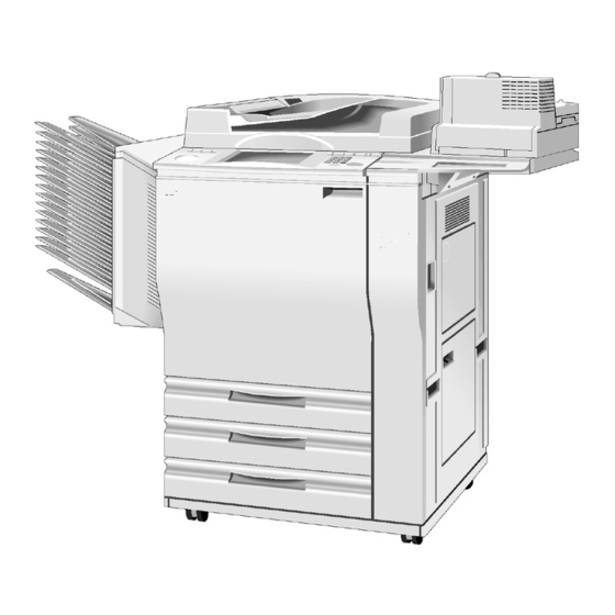
- Page 178 10 May 1996 MACHINE CONFIGURATION 1. MACHINE CONFIGURATION A172V500.wmf A172V501.wmf - Copier - - Full System - Item Machine Code Note • A172 is the edit version with a full color Copier operation panel. • A199 is the non-edit version with a black & A172 white operation panel.
- Page 179 SPECIFICATIONS 10 May 1996 2. SPECIFICATIONS 2.1 SPECIFICATIONS Specifications are subject to change without notice. Configuration: Console Copy Process: Dry electrostatic transfer system Resolutions: 400 dpi Gradations: 256 gradations Original Type: Sheet/book, object Original Size: Maximum: A3 (lengthwise), 11" x 17" (lengthwise) Original Alignment: Rear-left corner •...
- Page 180 10 May 1996 SPECIFICATIONS Warm-up Time: About 8 minutes (at 20°C or 68°F) • First Copy Time: Full Color (4 scans): 15.5 seconds • (A4 or 8 " x 11" sideways) Single Color: Black, Yellow, Magenta, Cyan: 8.8 seconds Red, Green, Blue, Orange, Light Green: 11.5 seconds.
- Page 181 SPECIFICATIONS 10 May 1996 Copy Tray Capacity: 100 sheets of paper Toner Replenishment: Bottle type (340g/bottle) • Reproduction Ratio: A4/A3 version: 25%, 50%, 65%, 71%, 75%, 82%, 93%, 100%, (Full Size), 115%, 122%, 141%, 200%, 400% + User ratio x 2 •...
- Page 182 10 May 1996 SPECIFICATIONS • Weight: Copier Only: 200 kg or 440.8 lb • Optional Equipment Dual Job Feeder • Sorter • Sorter Adapter • Projector Unit • Holder for Projector Unit • Key Counter • Interface Kit for Controller...
- Page 183 SPECIFICATIONS 10 May 1996 2.2 FUNCTIONS: BASIC MODEL VS EDIT MODEL This machine comes in two versions. Refer to the following table for features available on your machine. Functions Edit type Basic type Copy Image Density Adjustment (Auto/Manual) Auto Color Selection Full Color Back Single Color...
- Page 184 10 May 1996 SPECIFICATIONS 2.3 NEWLY-ADDED OPERATING FEATURES : Available : Not Available Features LILY (A172/A199) DFC-ALPHA (A109) Auto Image Density Full Color & Black Copy Black Copy only Auto Color Calibration Duplex Copying Twin Color Single Color 80 (+1) colors...
- Page 185 In the Area Editing mode, the outlines of the designated areas can be colored. 11. Image Overlay This function makes a copy merging images of two originals. 12. Area Editing mode LILY (A172) DFC-ALPHA (A109) Area Shape Rectangle, Polygon,Right Angle Rectangle, Polygon, Right Angle...
- Page 186 10 May 1996 SPECIFICATIONS MEMO...
- Page 187 MECHANICAL COMPONENT LAYOUT 10 May 1996 3. MECHANICAL COMPONENT LAYOUT A172V502.wmf Units different from A109 Bold Italic : Additional units : Modified units Bold 1-10...
- Page 188 10 May 1996 MECHANICAL COMPONENT LAYOUT 1. Pre-cleaning Corona Unit 20. Pressure Roller 2. By-pass Feed Table 21. Hot Roller 3. Transfer Belt 22. Development Ozone Filter 4. ID Sensor 23. Black/Cyan Development Unit 5. Belt Lubricant Bar 24. Drum Potential Sensor 6.
- Page 189 DRIVE LAYOUT 10 May 1996 4. DRIVE LAYOUT A172V503.wmf Units different from A109 Bold Italic : Additional units Bold : Modified units 1-12...
- Page 190 10 May 1996 DRIVE LAYOUT 1. Transfer Belt Position Clutch 15. Paper Feed Motor 2. Scanner Motor 16. 3rd Paper Feed Drive Pulley 3. Scanner Drive Pulley 17. Toner Collection Tank Drive Gear 4. Drum Timing Belt 18. 2nd Paper Feed Drive Pulley 5.
- Page 191 ELECTRICAL COMPONENT DESCRIPTIONS 10 May 1996 5. ELECTRICAL COMPONENT DESCRIPTIONS Refer to the electrical component layout on the waterproof paper in the pocket for symbols and index numbers. Symbol Name Function Index No. Printed Circuit Boards PCB1 DC power supply Provides dc power.
- Page 192 10 May 1996 ELECTRICAL COMPONENT DESCRIPTIONS Symbol Name Function Index No. Operation Panel Controls the operation panel. PCB23 Control Processes R/G/B video signals from the PCB24 scanner control board and sends Y/M/C/Bk video signals to the LD unit. IPU interface Changes the clock frequency of R/G/B video PCB25 signals and also sends the synchronizing...
- Page 193 ELECTRICAL COMPONENT DESCRIPTIONS 10 May 1996 Symbol Name Function Index No. Wire cleaner Drives the wire/grid cleaner Fan Motors Fusing exhaust Removes heat from around the fusing unit. Charge inlet Provides air flow around the drum charge section. Inner cooling Provides air flow around the toner tank and development units.
- Page 194 10 May 1996 ELECTRICAL COMPONENT DESCRIPTIONS Symbol Name Function Index No. Bk - Toner End Detects the toner end condition of Bk toner. C - Toner End Detects the toner end condition of C toner. M - Toner End Detects the toner end condition of M toner. Y - Toner End Detects the toner end condition of Y toner.
- Page 195 ELECTRICAL COMPONENT DESCRIPTIONS 10 May 1996 Symbol Name Function Index No. Vertical transport set Cuts the ac power line through RA1 and SW5/6 detects whether the vertical transport guide 78/79 is open or not. Main Provides power to the copier. When it is at the standby position, the electrical power is supplied only to the heaters (drum, optics anti-condensation,...
- Page 196 10 May 1996 ELECTRICAL COMPONENT DESCRIPTIONS Symbol Name Function Index No. 2nd separation roller Controls the up/down movement of the SOL9 separation roller in the 2nd feed station. 3rd separation roller Controls the up/down movement of the SOL10 separation roller in the 3rd feed station. Lamps Fusing Provides heat to the hot roller.
- Page 197 ELECTRICAL COMPONENT DESCRIPTIONS 10 May 1996 Symbol Name Function Index No. Counters Black total Keeps track of the total number of scans for black development in both black and color copy modes. Full color total Keeps track of the total number of scans for Yellow, Magenta, and Cyan development in both single and full color copy modes.
- Page 198 SECTION 2 DETAILED DESCRIPTIONS...
- Page 199 10 May 1996 MAJOR DIFFERENCES FROM THE DFC-ALPHA (A109) 1. MAJOR DIFFERENCES FROM THE DFC-ALPHA (A109) Item Contents Details Process Control Toner End The toner end detection software A toner end sensor has been Detection has been eliminated. added for each color. See 6.2 in section 2 for details.
- Page 200 MAJOR DIFFERENCES FROM THE DFC-ALPHA (A109) 10 May 1996 Item Contents Details Optics Cooling The filter material has changed. It The air flow has improved to Fan Filter is easier to replace the filter. reduce temperature rises in the optics cavity. For replacement, see section 5 for details.
- Page 201 10 May 1996 MAJOR DIFFERENCES FROM THE DFC-ALPHA (A109) Item Contents Details Transfer Roller Transfer The transfer roller heater has See 8.1 in section 2 for details. Belt/Roller been newly added to keep the Heater temperature around the transfer roller unit at 20°C. Transfer Roller The material of the transfer roller To improve transfer efficiency.
- Page 202 MAJOR DIFFERENCES FROM THE DFC-ALPHA (A109) 10 May 1996 Item Contents Details Operation The operation panel control Panel Control board has been newly added. — The main control board no longer controls the operation panel. Operation The operation panel self For easier servicing of the Panel Self diagnostics mode has been...
- Page 203 10 May 1996 PROCESS CONTROL 2. PROCESS CONTROL 2.1 LATENT IMAGE CONTROL 2.1.1 DRUM POTENTIAL SENSOR CALIBRATION RA#1 and RA #2 are packed in RL1 on RA #2 the High Voltage Supply Board – B. –300 V –600 V RA #1 Main Board A172D507.wmf Sensor Output...
- Page 204 PROCESS CONTROL 10 May 1996 2.1.2 GRADATION PATTERN DETECTION LD Power Level 4 0 m m 4 0 m m 2 n d 13th A172D510.img 14th A172D509.wmf A latent image of a 14-grade gradation pattern is created for each color (Bk, C, M, Y) by changing the LD input current.
- Page 205 10 May 1996 PROCESS CONTROL 2.2 TONER DENSITY CONTROL 2.2.1 V CORRECTION Pattern Density (mg/cm Copies Drum Potential A172D511.wmf A172D512.wmf Gain Value = –1 Average ≥ 3.8 Gain Value = ±0 Average ≤ 2.3 Gain value = +1 A172D513.wmf Even if the toner concentration is constant, the toner density sensor output gradually increases after new developer is installed because of developer characteristics.
- Page 206 PROCESS CONTROL 10 May 1996 2.2.2 FORCED TONER CONSUMPTION MECHANISM For customers that mainly make copies other than full color copies, the toners other than the selected colors are not used. For these toners, the amount of toner inside the development unit will gradually increase every 50 copies, since toner agitation is performed at this interval, and some toner is added at this time (see section 6.1).
- Page 207 10 May 1996 DRUM UNIT 3. DRUM UNIT 3.1 DRUM CHARGE This copier uses a single corona wire scorotron system to charge the drum. The corona wire applies a negative charge to the drum surface. The striped stainless steel grid plate makes the corona charge uniform and controls the negative charge on the drum surface to -650 V (standard) by applying a negative grid bias voltage.
- Page 208 DRUM UNIT 10 May 1996 3.2 DRUM CHARGE CORONA WIRE/GRID CLEANING A172D524.wmf A172D525.wmf The flow of air around the charge corona unit may deposit toner particles and paper dust on the corona wire or corona grid plate. These particles may interfere with charging and cause uneven charge on the drum.
- Page 209 10 May 1996 DRUM UNIT 3.3 DRIVE MECHANISM A172D500.wmf The drum is driven by the drum motor [A] through a timing belt [B]. By the use of a timing belt system, banding on copies are reduced due to the lower mechanical load. 2-11...
- Page 210 DRUM UNIT 10 May 1996 3.4 DRUM LUBRICATION MECHANISM A172D501.wmf A172D502.wmf While the drum rotates, the cleaning brush [A] distributes lubricant from the drum lubricant bar [B] to the surface of the drum. This mechanism improves the copy quality, especially for letter areas in full color mode, since it helps the toner transfer to the transfer belt.
- Page 211 10 May 1996 IMAGE PROCESSING 4. IMAGE PROCESSING 4.1 IPU SECTION BLOCK DIAGRAM A172D535.wmf 2-13...
- Page 212 IMAGE PROCESSING 10 May 1996 4.2 ACS (AUTO COLOR SELECTION) Signal Level M A X M I N *MIN: Also known as "RGB Common Data" A172D526.wmf In Auto Color Selection mode, the Black Copy mode or Full Color mode is automatically selected to match the original image.
- Page 213 10 May 1996 IMAGE PROCESSING When Color Priority is selected <ACS: Color Priority> Bk Conversion Data 2 5 5 : Letter areas : Photo areas UCR ratio: 100% U C R setting 1 2 5 5 R G B C o m m o n D a t a A172D527.wmf a) Letter areas The UCR ratio is set to 100% to reproduce the letter areas well.
- Page 214 IMAGE PROCESSING 10 May 1996 When B/W Priority is selected <ACS: B/W Priority> Bk Conversion Data 2 5 5 : Letter areas : Photo areas UCR ratio: 100% 2 5 5 R G B C o m m o n D a t a A172D528.wmf a) Letter areas The UCR (Under Color Removal) ratio is set to 100% to reproduce the letter...
- Page 215 10 May 1996 IMAGE PROCESSING 4.3 RGB FILTER RGB Input RGB Filter Filtering ADS (Full Color) RGB Output (to Color Correction) A172D529.wmf 4.3.1 Filtering To improve the image reproduction, the appropriate filter coefficients are applied to the R/B/G video signals, depending on the selected image modes (letter/photo) or the result of Auto Letter/Photo separation.
- Page 216 IMAGE PROCESSING 10 May 1996 4.4 COLOR CORRECTION (from RGB Filter) RGB Input Color Correction Positive/Negative Background Density Control Y M C B k A C C C P U Contrast Y M C B k S c a n M e m o r y Color A D S...
- Page 217 10 May 1996 IMAGE PROCESSING 4.4.1 Image Modes RGB video signals are converted to YMCBk video signals using a color conversion table. A172D530.wmf a) Printed Photo/Glossy Photo mode A suitable color conversion table for Printed Photo or Glossy Photo mode is applied to improve the reproduction of such originals.
- Page 218 IMAGE PROCESSING 10 May 1996 4.4.2 Background Density Control R G B Output Data Darker Setting Lighter Setting RGB Input Data A172D531.wmf There a 9 levels of background density controls. a) Lighter setting Small effect on the high image density areas, but the low image density areas are reproduced lighter or erased.
- Page 219 10 May 1996 IMAGE PROCESSING 4.4.3 Contrast R G B Output Data W e a k e r Stronger RGB Input Data A172D532.wmf Contrast between light and dark areas of the image can be adjusted. There are over 9 levels. a) Strong setting The density of the dark image areas is increased and the density of the light image areas is decreased.
- Page 220 IMAGE PROCESSING 10 May 1996 4.4.4 Auto Image Density Control (B/W, Twin Color, Single Color) This mode prevents the background of an original from appearing on copies. The Auto Image Density Level can be changed using the User Tools. (There are 5 levels.) When B/W, Single Color, or Twin Color and Auto Image Density mode are selected, this function combines the Background Density Control and...
- Page 221 10 May 1996 IMAGE PROCESSING 4.5 ACC (AUTO COLOR CALIBRATION) Test Pattern Photo mode Letter mode (4 scan) A172D534.wmf Target γ Actual γ Image Density A172D540.wmf Auto Color Calibration can be performed using the User Tools. A test pattern, including the patterns for Letter mode and Photo mode, will be printed first.
- Page 222 IMAGE PROCESSING 10 May 1996 4.6 YMCBk FILTER In addition to the RGB filter, the most suitable software filter is applied to YMCBk video signals to improve the image reproduction. • High Contrast filter (emphasizing edges) • Smoothing filter Soft Sharp (Smoothing) (Emphasizing Edges)
- Page 223 10 May 1996 DEVELOPMENT 5. DEVELOPMENT 5.1 DEVELOPMENT SLEEVE CLEANING A172D506.wmf To achieve a faster CPM for black and white originals when copying 1 to 1 or using Auto Color Select (ACS) mode, the development sleeve cleaning mode previously performed for every original is now performed periodically. For A4 or smaller size originals, a maximum of 40 black and white copies can be made without the machine stopping to perform development sleeve cleaning (20 copies for originals larger than A4 size).
- Page 224 TONER TANK 10 May 1996 6. TONER TANK 6.1 TONER AGITATION One Cycle Clockwise Stop Counter Clockwise 1.0S 0.5S A172D504.wmf Cycle Clockwise Stop Counter Clockwise A172D503.wmf Toner End Detection is done here A172D505.wmf Under the following conditions, the toner agitator [A] inside each toner tank rotates to agitate the toner inside the toner tank.
- Page 225 10 May 1996 TONER TANK 6.2 TONER END DETECTION A172D503.wmf Four toner end sensors [A] (which are piezoelectric) are installed on the toner tank to monitor the near end condition for each color toner. Toner end detection is performed during toner agitation, and the detection sequence is as follows.
- Page 226 TRANSFER BELT UNIT 10 May 1996 7. TRANSFER BELT UNIT 7.1 TRANSFER BELT BIAS Transfer Belt Bias (Face Side: Normal Humidity) Copy Mode 1410 1410 1410 1410 Dev. 1490 1490 1490 Cycle 1575 1575 1660 Transfer Belt Bias Depending on Humidity Range (1C Mode: Face Side) Bias 2075 1740...
- Page 227 10 May 1996 TRANSFER BELT UNIT 7.2 TRANSFER BELT LUBRICATION A172D515.wmf A172D516.wmf A 1 7 2 / A 1 9 9 A 1 0 9 Amount 1 0 0 1 5 0 Copy Count A172D517.wmf The transfer belt lubricant bar [A] on the transfer belt cleaning unit [B] applies lubricant directly to the transfer belt [C] after every copy.
- Page 228 TRANSFER ROLLER UNIT 10 May 1996 8. TRANSFER ROLLER UNIT 8.1 TRANSFER BELT/ROLLER HEATER CONTROL A172D518.wmf H E A T E R T H E R M O S W I T C H A172D519.wmf The resistance of the transfer roller [A] changes with the environment. It is especially at low temperatures.
- Page 229 10 May 1996 TRANSFER ROLLER UNIT 8.2 TRANSFER ROLLER BIAS <Transfer Roller Bias Coefficient by Humidity Range (1C Mode: Face Side; Normal Paper)> Bias 1 7 2 9 1 5 7 3 1 4 0 4 1 3 0 0 1 0 0 1 L o w 1 L o w 2...
- Page 230 TRANSFER ROLLER UNIT 10 May 1996 8.3 TRANSFER ROLLER LUBRICATION A172D539.wmf The transfer roller lubricant bar [A] above the cleaning blade [B] continuously applies lubricant directly to the transfer roller [C]. Four spring plates [D] under the transfer roller guide [E] press the lubricant bar against the transfer roller.
- Page 231 10 May 1996 TRANSFER ROLLER UNIT 8.4 PAPER DISCHARGE A172D521.wmf A172D522.wmf Discharge Plate Output Normal Paper Thick Paper Duplex: Face Duplex: Back 4000 V 3500 V 4000 V 4000 V The high voltage supply board -D [A] applies ac voltage to the discharge plate [B].
- Page 232 FUSING UNIT 10 May 1996 9. FUSING UNIT 9.1 ROLLER CLEANING MECHANISM A172D523.wmf The cleaning roller [A], which is always in contact with the hot roller [B], collects the toner and paper dust adhering to the surface of the hot roller. The collected matter is scraped off by a stainless steel blade [C].
- Page 233 10 May 1996 FUSING UNIT 9.2 FUSING TEMPERATURE CONTROL Each rollers are controlled at the temperature shown in the table below. During Copying Manual Duplex Stand-by Normal OHP/Thick Paper (Back Side) 2C, 3C, 4C 2C, 3C, 4C 2C, 3C, 4C Normal:160 Normal:170 Roller Thick...
- Page 234 OPERATION PANEL 10 May 1996 10. OPERATION PANEL This operation panel has an LCD (640 x 480 dots). Most of the keys for functions are displayed on the LCD (Touch panel). There are two versions of the LCD. • Basic Model (A199): Black/White LCD •...
- Page 235 10 May 1996 OPERATION PANEL 10.2 OPERATION CONTROL BOARD 8 bit 8 bit 8 bit 3 bit + 3 bit + 2 bit = 8 bit A172D537.wmf Resolution Enlargement Ratio Full Size 25 dpi 100% Enlarge 1 50 dpi 200% Enlarge 2 67 dpi 264%...
- Page 236 OPERATION PANEL 10 May 1996 10.3 OP-PORT Operation Control Board OP-PORT 2 OP-PORT 1 L C D +5 V +12 V B U Z Z E R –12 V LED DATA S P E A K E R LED MATRIX LED MATRIX DRI VER D E C O D E R...
- Page 237 SECTION 3 INSTALLATION...
- Page 238 10 May 1996 INSTALLATION REQUIREMENTS 1. INSTALLATION REQUIREMENTS 1.1 ENVIRONMENT 1. Temperature Range: 10°C to 32°C (50°F to 89°F) 2. Humidity Range: 15% to 90% RH 3. Ambient Illumination: Less than 2,000 lux (Do not expose to direct sunlight.) 4. Ventilation: Minimum space 20 m Room air should turn over at least 30 m...
- Page 239 INSTALLATION REQUIREMENTS 10 May 1996 1.3 MINIMUM SPACE REQUIREMENTS Place the copier near the power source, providing clearance as shown: Copier only A172I505.wmf Full system A172I506.wmf NOTE: A space of at least 10 cm (3.9") at the rear of the machine is necessary for smooth air flow into the machine.
- Page 240 10 May 1996 INSTALLATION REQUIREMENTS 1.4 POWER REQUIREMENTS 1. Input voltage level: 115 V/60 Hz: More than 12 A 220 ∼ 240 V, 50/60 Hz: More than 7 A 2. Permissible voltage fluctuation: 10% 3. Do not set anything on the power cord. NOTE: a) Make sure the plug is firmly inserted in the outlet.
- Page 241 COPIER (A172/A199) 10 May 1996 2. COPIER (A172/A199) 2.1 ACCESSORY CHECK Check the quality and condition of the accessories in the box against the following list: 2.1.1 Copier 1. Operating Instructions (except -27 machines)......1 2. NECR (-17, -27, and -29 machines only) ......... 1 3.
- Page 242 10 May 1996 COPIER (A172/A199) 2.2 COPIER SEPARATION A172I509.img A172I510.img The machine can be separated into two units (the main frame and the paper supply unit). Separation of the machine will help the transportation to the customer’s site. 1. Open the front door and remove the front securing brackets [A] (4 screws each).
- Page 243 COPIER (A172/A199) 10 May 1996 2.3 COPIER INSTALLATION PROCEDURE NOTE: Since the installation procedure is not packed with the copier as an accessory, always bring this manual with you. A172I511.img NOTE: a) Before performing the following installation procedure, be sure to plug in the copier power cord due to the change of material of the transfer roller.
- Page 244 10 May 1996 COPIER (A172/A199) A172I512.img A172I500.wmf 1. Remove the tape strips. 2. Open the front doors then remove the tape strips [A] around the toner tank and the tapes [B] securing the registration guide plates (knobs B and B...
- Page 245 COPIER (A172/A199) 10 May 1996 A172I513.img A172I514.img A172I515.img 3. Remove the right inner cover [A] (3 screws) and the bracket [B] securing the toner tank to the front side plate (1 screw). 4. Remove the bracket [C] securing the transfer roller unit (1 screw). 5.
- Page 246 10 May 1996 COPIER (A172/A199) A172I504.img A172I501.wmf A172I503.img 7. Lower the toner collection duct [A] (1 hook [B]). 8. Remove the yellow toner supply receptacle [C] (1 screw). 9. Disconnect the four connectors [D] and free them from the three harness clamps.
- Page 247 COPIER (A172/A199) 10 May 1996 A172I516.img A172I517.img A172I518.wmf 12. Carefully pull and remove the transfer belt unit [A]. (While holding the handle [B], release the lever [C]) NOTE: There are stands at the rear side of the transfer belt unit. After pulling out the unit out of the machine, stand the transfer belt unit as shown.
- Page 248 10 May 1996 COPIER (A172/A199) A172I519.img A172I520.img A172I521.img 15. Remove the magenta/yellow development unit [A] (1 release lever [B]) and remove the black/cyan development unit [C] (1 release lever [D]). 16. Disconnect the drum’s toner collection pipe [E] as shown. 17.
- Page 249 COPIER (A172/A199) 10 May 1996 A172I522.img A172I523.img 19. Turn the drum unit over. NOTE: Let the unit rest on it’s casing. 20. Remove the drum protective sheet [A]. 21. Loosen then move the knob [B]. (Move the knob from [C] to [D].) •...
- Page 250 10 May 1996 COPIER (A172/A199) A172I518.wmf A172I524.img 24. Reinstall the following units or parts in the machine as follows. 1) Slide in the drum unit and secure it to the shaft with the knob screw. 2) Set the drum stay [A] in position and secure the drum unit (2 screws). 3) Remove the drum stay [A] and reinstall the quenching lamp, toner collection tube and development units.
- Page 251 COPIER (A172/A199) 10 May 1996 A172I525.img 25. Confirm the belt bias roller [A] is in the release position (innermost position) as shown. If not, turn the shaft [B] with a flat head screwdriver until the belt bias roller comes to the release position. NOTE: If the belt bias roller is not in the release position, it will touch the drum and damage it.
- Page 252 10 May 1996 COPIER (A172/A199) CAUTION 1. Be careful when handling the fusing unit. It is hot. 2. Take care not to spill silicone oil on the floor. If silicone oil spills on the floor, immediately clean it with a silicone oil remover. Silicone oil is very slippery and can cause someone to fall.
- Page 253 COPIER (A172/A199) 10 May 1996 A172I528.img A172I507.wmf A172I508.wmf 30. Remove the fusing handle cover [A] (2 screws) and the fusing top cover [B] (1 screw). 31. Prime the oil supply pad with silicone oil [C]. 32. Remove the oil cap [D] and fill the tank with silicone oil to its max level [E]. 33.
- Page 254 10 May 1996 COPIER (A172/A199) 36. Locate the switch actuator [A] inside the right door and actuate the front safety switch. A172I529.img 37. Plug in the power cord and turn on the main switch. 38. Enter SP mode as follows. 1) Press the clear modes key.
- Page 255 COPIER (A172/A199) 10 May 1996 A172I531.img A172I530.img 41. Remove the black toner supply receptacle [A] (1 screw). NOTE: Refer to the toner tank lid for the color of the development unit. 42. Remove the developer supply funnel [B] from the bracket [C] and clean the inner surface.
- Page 256 10 May 1996 COPIER (A172/A199) 50. Install the cyan, magenta and yellow developer in the same manner as black developer installation (step #40 to #49). NOTE: To select the "color development drive motor ON" mode, enter "69" for color instead of 68 for black (refer to step #45). 51.
- Page 257 COPIER (A172/A199) 10 May 1996 55. Touch the SP Data Output key [A]. 56. Check whether V has the same values as V for all colors (Bk, Y, M, C). If not, touch the Index key [B] then return to the test mode page 3 to perform developer initial setting (step 53) again.
- Page 258 10 May 1996 COPIER (A172/A199) A172I532.img A172I502.wmf 57. Put the toner tank [A] on the Accuride rails (2 screws). 58. Add toner [B] for all colors. • NOTE: Read the instructions on the box for how to add toner. • Before reinstalling the toner tank, wait at least 30 seconds to let the toner settle.
- Page 259 COPIER (A172/A199) 10 May 1996 64. Wait 5 minutes to ensure that no residual voltage remains on the drum. NOTE: The process control self check (step 67) must be performed when there is no residual voltage on the drum. 65. Touch the SP Mode key [A] to enter the SP mode. 66.
- Page 260 10 May 1996 COPIER (A172/A199) 70. Touch the SP Test Mode key [A]. 71. Touch the Next key [B] to open page 4. 72. Touch the Process Control Self Check Start key [C]. After the self check is completed, the machine stops automatically. CAUTION While process control is taking place, do not touch the knob, drum stay, or drum shaft.
- Page 261 COPIER (A172/A199) 10 May 1996 74. Touch the SP Data Output key [A]. 75. Touch the Next key [B] and open page 3. 76. Check the V and V [C] for each color. If the difference between ’Target’ and ’Actual’ for any color exceeds 5, wait 5 minutes and go back to step 72 and perform the process control self check again.
- Page 262 10 May 1996 COPIER (A172/A199) 78. Touch the Exit key [A]. 79. Turn off the main switch and place the accessory switch actuator in its original position. 80. Reinstall the right inner cover (3 screws) and turn on the main switch. 81.
- Page 263 COPIER (A172/A199) 10 May 1996 2.4 PAPER SIZE CHANGE A172I533.wmf At the customer’s request, change the paper size for the 3rd feed tray as follows. 1. Draw out the paper feed tray [A]. 2. Change the position of the front and the rear side fences [B] (1 screw each) and the end fence [C] (1 screw) to match the paper size.
- Page 264 10 May 1996 COPIER (A172/A199) 3. Enter SP Mode as follows: 1) Press the clear modes key. 2) Wait for 2 or 3 seconds while the display returns to the initial screen. 3) Enter "107". 4) Hold down the clear/stop key for more than 3 seconds. 4.
- Page 265 COPIER (A172/A199) 10 May 1996 7. Touch the Exit key [A] to exit SP mode. 8. Check machine operation and copy quality. 3-28...
- Page 266 10 May 1996 COPIER (A172/A199) 2.5 OPTIONAL HOLDER (A702-18) A172I534.img A172I535.img 1. Remove the right upper cover [A] (2 screws). 2. Install the holder base bracket [B] (6 screws). 3. Install the holder cover [C] (2 screws). 3-29...
- Page 267 COPIER (A172/A199) 10 May 1996 A172I536.img A172I537.img 4. Install the lower cover [A] (2 truss screws). 5. Install the front cover [B] (1 truss screw). 3-30...
- Page 268 10 May 1996 COPIER (A172/A199) 2.6 KEY COUNTER INSTALLATION A172I538.img 1. Remove the following parts. (Refer to Exterior And Inner Covers.) • Upper rear cover • Right inner cover • Upper right cover 2. Remove the key counter cover [A] (2 screws) from the key counter holder bracket [B].
- Page 269 COPIER (A172/A199) 10 May 1996 2.7 UPPER AND LOWER TRAY HEATERS (OPTIONS) A172I539.img A172I540.img A172I541.img NOTE: Both heaters are available as service parts. 1. Attach the heater to the bracket (2 M4 x 10 screws). 2. Pull out and remove all the paper feed trays [A] (4 screws each). 3.
- Page 270 10 May 1996 DUAL JOB FEEDER (A610) 3. DUAL JOB FEEDER (A610) 3.1 ACCESSORY CHECK Check the accessories against the following list: Description Q’ty 1. Installation Procedure............1 2. NECR (-17, -27 only) ............1 3. Stepped Screw ..............2 4.
- Page 271 DUAL JOB FEEDER (A610) 10 May 1996 3.2 INSTALLATION PROCEDURE A610I500.wmf A610I501.wmf A610I503.img A610I502.wmf 1. Remove the tape strips and the cushions [A] as shown. 2. While raising the lock plate [B], slide the platen cover [C] to the right and remove it.
- Page 272 10 May 1996 DUAL JOB FEEDER (A610) A610I505.wmf A610I504.wmf A610I506.wmf 4. Install two stepped screws [A]. 5. Attach the sponge retainer [B] to the top cover of the copier as shown. 6. Mount the DF on the copier by inserting the two stepped screws into the holes in the DF hinge [C], then slide the DF to the front, as shown.
- Page 273 DUAL JOB FEEDER (A610) 10 May 1996 F a c e u p Mit der Schriftseite n a c h o b e n F a c e i m p r i m é e d e u u u s Faccia in su Boca arriba A610I515.wmf...
- Page 274 10 May 1996 SORTER (A322) 4. SORTER (A322) 4.1 ACCESSORY CHECK Check the accessories against the following list: Description Q’ty 1. Installation Procedure............1 2. NECR (-17 only) ............... 1 3. Stud .................. 2 4. Knob Screw ..............2 5. Sorter Bin................15 6.
- Page 275 SORTER (A322) 10 May 1996 4.2 INSTALLATION PROCEDURE A322I500.wmf A322I501.img NOTE: To install this sorter on the A172/A199 copier, the A527 sorter adapter kit (option) is necessary. 1. Remove four pieces of tape: Sorter Top Cover [A] (1 pc) Transport Guide [B] (2 pcs) Sorter Harness [C] (1pc) 2.
- Page 276 10 May 1996 SORTER (A322) A322I502.img A322I503.img 3. Remove the upper rear cover [A] (4 screws). 4. Open the front doors, then remove the left inner cover [B] (1 screw). 5. Remove the upper left cover [C] (4 screws). 6. Remove the 5 caps [D]. 7.
- Page 277 SORTER (A322) 10 May 1996 A322I504.img A322I505.img 9. Install the studs [A]. 10. Install the upper guide plate [B] (2 screws). 11. Install the lower guide plate [C] (2 screws). 12. Remove the sorter top cover [D] (3 screws). 13. Remove the sorter rear cover [E] (4 screws). 14.
- Page 278 10 May 1996 SORTER (A322) A322I506.img 15. Remove the rear cover mounting bracket [A] (1 screw). 16. Install the air outlet plate [B] where the rear cover mounting bracket was previously installed (1 screw). Use the screw which was used for the rear cover mounting bracket.
- Page 279 SORTER (A322) 10 May 1996 A322I507.wmf A322I508.wmf 17. Connect the accessory harness connectors [A] to the fan assembly connectors. 18. Install the fan assembly [B] on the sorter rear frame (3 screws and 1 connector). NOTE: Make sure to run the harness through the cutout [C] as shown. 19.
- Page 280 10 May 1996 SORTER (A322) A322I509.img A322I510.img 21. Remove the protective cover and secure the 4p connector [A]. 22. Secure the grounding wire [B]* (1 grounding screw with toothed washer). NOTE*: For all models other than those intended for North America, the green wire is intended as a functional earth and should be connected as shown.
- Page 281 FILM PROJECTOR (A718) 10 May 1996 5. FILM PROJECTOR (A718) 5.1 ACCESSORY CHECK Make sure that each accessory listed in the following table is in the box. Also check the condition of each item. Description Q’ty 1. Mirror Unit ................. 1 2.
- Page 282 10 May 1996 FILM PROJECTOR (A718) 5.2 INSTALLATION PROCEDURE A718I520.wmf A718I521.wmf NOTE: Holder Type C (A702-18) must be installed before starting the following procedure. 1. Remove the lower cover [A] from the holder bracket (2 screws). 2. Remove the cover plate [B] from the holder. 3.
- Page 283 FILM PROJECTOR (A718) 10 May 1996 A718I522.wmf A718I523.wmf 6. Remove two rubber caps [A] and cover [B] (4 screws). 7. Remove the shield plate [C] (2 screws). 8. Open the front cover and remove the front cover assembly [D] (2 screws). 9.
- Page 284 10 May 1996 FILM PROJECTOR (A718) A718I503.wmf A718I524.wmf A718I507.wmf 10. Remove the lamp cover [A] (1 screw) and open the reflector cover [B]. Then, plug the projector lamp [C] into the socket. Then close the reflector cover. NOTE: The projector lamp should be inserted horizontally until it stops. 11.
- Page 285 FILM PROJECTOR (A718) 10 May 1996 A718I509.wmf 14. Adjust the height as follows. 1) Place the film position sheet [A] on the exposure glass, aligning it at the rear left corner. 2) Put the mirror unit [B] on the exposure glass by aligning the holes with the positioning pins [C] on the lens cover.
- Page 286 10 May 1996 FILM PROJECTOR (A718) A718I511.wmf 3) Insert the film strip holder [A] into the film projector unit at the base film setting position. NOTE: Push the film strip holder gently to confirm that the film strip holder has been inserted correctly. 4) Turn on the test switch [B] on the projector control board and turn on the projector unit main switch [C].
- Page 287 FILM PROJECTOR (A718) 10 May 1996 A718I513.img A718I512.wmf A718I514.wmf A718I515.wmf 15. Adjust the angle [A] of the mirror unit as follows: 1) Turn on the copier main switch and wait for the ready condition. 2) Open the lens cover and position the mirror unit on the exposure glass. 3) Put the correction filter [B] for positive films in the filter slot.
- Page 288 10 May 1996 FILM PROJECTOR (A718) A718I516.wmf A718I514.wmf 8-2) When the trailing part is dark [A]. a) Move the front and rear arm guides [B] to the right so that the mirror angle is reduced (2 screws each). NOTE: Position the arm guides at the same location at front and rear, using the ruler decals.
- Page 289 CONTROLLER INTERFACE TYPE-C (A583-05) 10 May 1996 6. CONTROLLER INTERFACE TYPE-C (A583-05) 6.1 ACCESSORY CHECK Make sure that each accessory listed in the following table is in the box. Also check the condition of each item. Description Q’ty 1. Controller Interface Board ..........1 2.
- Page 290 10 May 1996 CONTROLLER INTERFACE TYPE-C (A583-05) 6.2 INSTALLATION PROCEDURE 1. Remove the covers. A583I500.img CAUTION Turn off the main switch and unplug the machine before starting the following procedure. 1. Open the front doors and remove the toner tank unit [A] (2 screws). 2.
- Page 291 CONTROLLER INTERFACE TYPE-C (A583-05) 10 May 1996 2. Attach the PTL (Pre-Transfer Lamp) to the belt cleaning unit. A583I501.wmf A583I502.wmf 1. Lower the toner collection duct (1 hook). 2. Disconnect the three connectors and free them from the three harness clamps.
- Page 292 10 May 1996 CONTROLLER INTERFACE TYPE-C (A583-05) 3. Install the interface board and harness. A583I503.img A583I504.img 1. If the DJF is equipped on the copier, secure the DJF to the scanner unit with the DJF fixing belt [A] as shown. If the Film Projector Unit is installed on the copier, remove the mirror unit.
- Page 293 CONTROLLER INTERFACE TYPE-C (A583-05) 10 May 1996 A583I505.img A583I506.img 8. Route the harness above the left rail of the 1st tray [A] from the left side to the rear. 9. Place the controller interface harness bracket [B] on the left side frame and secure it with the grounding wire (1 screw) [C].
- Page 294 10 May 1996 CONTROLLER INTERFACE TYPE-C (A583-05) [Fig. 2] A583I508.wmf A583I507.wmf [Fig. 1] A583I509.wmf A583I510.wmf 12. Install the controller interface board [A] by connecting it to CN308 [B] of the IPU board (4 screws). 13. Connect the white 2P connector [C] to CN301 [D] of the controller interface board via the fuse harness [E].
- Page 295 CONTROLLER INTERFACE TYPE-C (A583-05) 10 May 1996 A583I511.wmf 18. Secure the interface harness with the three harness clamps and reinstall the timing belt as shown. NOTE: Route the remaining part of the harness along the top of the AC/DC Drive Board as shown. Position the harness near by the rear side plate so that the harness won’t touch any moving parts such as timing belts and motors.
- Page 296 SECTION 4 SERVICE TABLES...
- Page 297 10 May 1996 SERVICE PROGRAM MODE 1. SERVICE PROGRAM MODE 1.1 SERVICE PROGRAM MODE OPERATION The service program (SP) mode is used to check electrical data, change modes, and adjust values. 1.1.1 Service Program Access Procedure 1. Press the clear modes key. 2.
- Page 298 SERVICE PROGRAM MODE 10 May 1996 1.1.3 To Return to the Index Menu 1. Return to the index menu by touching [A] on the display. 1.1.4 Change the Menu Screen 1. To move to the next page, touch [B]. 2. To move to the previous page, touch [C].
- Page 299 10 May 1996 SERVICE PROGRAM MODE 1.1.6 To Input Settings keys [A] are displayed as shown, touch the key or key to change the setting. In this case, the default setting is 00. If the keys display numbers, as shown: 1) Touch the key [B].
- Page 300 SERVICE PROGRAM MODE 10 May 1996 1.2 SERVICE PROGRAM MODE TABLE • NOTE: Shaded items should not be adjusted in the field. • Items written in bold italic letters are newly added service programs to the base copier (DFC-Alpha). • The SP mode screens are sample ones.
- Page 301 10 May 1996 SERVICE PROGRAM MODE Page Item Function Note Lead Edge Shifts the vertical image Evaluate the width of the blank Registration position by changing the ON area at the leading edge of the (Printing) timing of the registration clutch. test pattern image.
- Page 302 SERVICE PROGRAM MODE 10 May 1996...
- Page 303 10 May 1996 SERVICE PROGRAM MODE Page Item Function Note By-pass Feed * Normal Paper and For by-pass feed, there are * OHP/Thick Paper adjustments for normal paper, Changes the by-pass feed OHP, and thick paper mode. Adjustable range: –9.9 ∼ 9.9 mm clutch on time for each paper kind to adjust the paper buckle Thick 2nd Feed...
- Page 304 SERVICE PROGRAM MODE 10 May 1996...
- Page 305 10 May 1996 SERVICE PROGRAM MODE Page Item Function Note Setting P-con Factory use only Do not adjust in the field. OFF Mode Default:(for all the colors) ILD: 128 Toner Max. M/A Sets the maximum toner Do not adjust in the field. <1>...
- Page 306 SERVICE PROGRAM MODE 10 May 1996 4-10...
- Page 307 10 May 1996 SERVICE PROGRAM MODE Page Item Function Note Transfer Belt Adjusts the transfer belt bias Do not adjust in the field. Bias (Back voltage for each transfer Default: Side: Normal process of the back side copy 1410 1490 Humidity) 1575 1660...
- Page 308 SERVICE PROGRAM MODE 10 May 1996 4-12...
- Page 309 10 May 1996 SERVICE PROGRAM MODE Page Item Function Note Transfer Roller Sets the coefficient (%) for the Do not adjust in the field. Bias Coefficient transfer roller bias (normal Adjustable range: 0 ~ 255 By Humidity humidity) for other humidity Range ranges.
- Page 310 SERVICE PROGRAM MODE 10 May 1996 4-14...
- Page 311 10 May 1996 SERVICE PROGRAM MODE Page Item Function Note Blank Margin Adjusts the width of the margins Adjustable range: –5 ∼ 5 mm at the edges of the copy paper. Right edge: –5 ∼ 5 mm Main Scan Lead Edge: Left edge: –5 ∼...
- Page 312 SERVICE PROGRAM MODE 10 May 1996 4-16...
- Page 313 10 May 1996 SERVICE PROGRAM MODE Page Item Function Note Exposure Lamp Adjusts the exposure lamp input Default: 70 V Adjustable range: 50 ∼ 75 V Voltage voltage during factory adjustment. Do not adjust in the field. This does not influence the exposure lamp input voltage during copying.
- Page 314 SERVICE PROGRAM MODE 10 May 1996 1.2.2 [2] SP Test 4-18...
- Page 315 10 May 1996 SERVICE PROGRAM MODE Page Item Function Note Test Pattern Adjusts the laser power for the Default: 255 <2> Condition test pattern density for the 256 This function effects the test grades. patterns in the bottom part of SP <2>-2.
- Page 316 SERVICE PROGRAM MODE 10 May 1996 4-20...
- Page 317 10 May 1996 SERVICE PROGRAM MODE Page Item Function Note Forced Toner Factory use only Do not use in the field. Supply Operation Do not make a copy with new Toner Density Starts and stops the toner Initial Setting density sensor’s initial setting. developer before the initial Indicates the gain data of each developer setting.
- Page 318 SERVICE PROGRAM MODE 10 May 1996 4-22...
- Page 319 10 May 1996 SERVICE PROGRAM MODE Page Item Function Note Developer Starts and stops the developer The Bk or color development Collection Bk collection. drive motor rotates and the selected color sleeve motor rotates forwards and reverse alternatively. Process Control Starts and stops the process Perform this mode when the Self Check...
- Page 320 SERVICE PROGRAM MODE 10 May 1996 4-24...
- Page 321 10 May 1996 SERVICE PROGRAM MODE Page Item Function Note SC Detection Disables the self-diagnostic Default: Reset (enable) OFF Mode function. Jam Detection Disables jam detection (ON Default: Reset (enable) OFF Mode check). Printer Free Run Starts printer free run mode.
- Page 322 SERVICE PROGRAM MODE 10 May 1996 1.2.3 [3] SP Data Output 4-26...
- Page 323 10 May 1996 SERVICE PROGRAM MODE Page Item Function Note Fusing Temp. Indicates the hot roller/pressure roller temperature based on the output of the thermistors. Potential Sensor Indicates the potential sensor V1: Potential sensor output at a Calibration Data calibration data. drum potential of 300 V V2: Potential sensor output at a <3>...
- Page 324 SERVICE PROGRAM MODE 10 May 1996 4-28...
- Page 325 10 May 1996 SERVICE PROGRAM MODE Page Item Function Note Drum Potential Indicates the target and actual VD: charge potential Control Output data related to process control. VL: exposed drum potential <3> VB: development bias γ : development gamma VK: development reference data Bk Level DA1 Displays DA1 settings.
- Page 326 SERVICE PROGRAM MODE 10 May 1996 1.2.4 [4] SP Special Feature 4-30...
- Page 327 10 May 1996 SERVICE PROGRAM MODE Page Item Function Note Auto Process Factory use only "PID" setting must be used. Control Self check Toner Supply Selects toner supply mode. Default: Fuzzy Control Mode "Fuzzy" setting must be used. Selection Transfer Bias Selects the output voltage for Default: Normal Humidity...
- Page 328 SERVICE PROGRAM MODE 10 May 1996 4-32...
- Page 329 10 May 1996 SERVICE PROGRAM MODE Page Item Function Note Printer γ Adjusts image density for each Do not change the STEP data color in letter mode. (Letter in the field. Correction Data mode rough adjustment) See section 5, color balance Rough adjustment.
- Page 330 SERVICE PROGRAM MODE 10 May 1996 4-34...
- Page 331 10 May 1996 SERVICE PROGRAM MODE Page Item Function Note Printer γ Adjusts each color image Do not adjust in the field. <4> density (Letter mode fine Default: 5 for all Correction Data adjustment) Fine Adjustment =Printed Photo= Printer γ Not used.
- Page 332 SERVICE PROGRAM MODE 10 May 1996 4-36...
- Page 333 10 May 1996 SERVICE PROGRAM MODE Page Item Function Note Printer γ Not used. Default: 5 for all (Indication only) Correction Data <4> Fine Adjustment =Copied Photo= Printer γ Not used. Default: 5 for all (Indication only) Correction Data Fine <4>...
- Page 334 SERVICE PROGRAM MODE 10 May 1996 4-38...
- Page 335 10 May 1996 SERVICE PROGRAM MODE Page Item Function Note Coin Lock Not used. Default: No Connection Key Card Count Not used. Default: Paper Exit Timing Set User Enables user code mode. Default: OFF Code(s) The key counter shorting connector should be disconnected to enable user code mode.
- Page 336 SERVICE PROGRAM MODE 10 May 1996 4-40...
- Page 337 10 May 1996 SERVICE PROGRAM MODE Page Item Function Note PM Counter Selects the PM alarm interval If you do not use the PM alarm, <4> after counter clear. set this to "0". Default: 0 Tray Paper Size Selects the paper size and <4>...
- Page 338 SERVICE PROGRAM MODE 10 May 1996 1.2.5 [5] Jam/SC Counter 4-42...
- Page 339 10 May 1996 SERVICE PROGRAM MODE Page Item Function Note Total SC Indicates the total number of See section 6 for details on <5> service calls for each SC code. each SC code. SCs that have not occurred at least once are not displayed. Jam Counter Indicates the total number of jams which have occurred in...
- Page 340 SERVICE PROGRAM MODE 10 May 1996 1.2.6 [6] Operation Counter 4-44...
- Page 341 10 May 1996 SERVICE PROGRAM MODE Page Item Function Note Original Counter Indicates the total number of originals that have been copied in each color mode. <6> Copy Counter Indicates the total number of Count up method is the same scans, broken down by copy as that for mecanical counters.
- Page 342 SERVICE PROGRAM MODE 10 May 1996 4-46...
- Page 343 10 May 1996 SERVICE PROGRAM MODE Page Item Function Note Copies by Indicates the total number of Paper Feed copies broken down by paper <6> feed station. Indicates the total number of copies made in APS mode. Copies by Indicates the total number of Magnification copies broken down magnification range.
- Page 344 SERVICE PROGRAM MODE 10 May 1996 4-48...
- Page 345 10 May 1996 SERVICE PROGRAM MODE Page Item Function Note Image Creation Indicates the total number of <6> copies made in image creation modes. Color Creation: Indicates the total number of Whole Image copies broken down by color creation mode used for the whole copy image.
- Page 346 SERVICE PROGRAM MODE 10 May 1996 4-50...
- Page 347 10 May 1996 SERVICE PROGRAM MODE Page Item Function Note Area Shapes Indicates the total number of editing areas broken down by <6> area shape. Special Indicates the total number of Accessory copies for each peripheral. Electronic Not used. Counter Setting <6>...
- Page 348 SERVICE PROGRAM MODE 10 May 1996 1.2.7 [7] Counter Clear 4-52...
- Page 349 10 May 1996 SERVICE PROGRAM MODE Page Item Function Note Counter All Clear Clears all counters Procedure: <7> 1. Touch the clear key. Operation Clears all operation counters 2. The display asks Yes or No. Counter Clear If you are sure you want to Jam/SC Counter Clears all jam and SC counters <7>...
- Page 350 SERVICE PROGRAM MODE 10 May 1996 1.2.8 [8] Printer 4-54...
- Page 351 10 May 1996 SERVICE PROGRAM MODE Page Item Function Note Printer γ Adjusts each color’s image Do not change the STEP density. values in the field. Correction Dat. (Halftone mode rough Rough adjustment) Adjustment =Halftone= γ Correction Saves or recalls the printer γ The printer γ...
- Page 352 SERVICE PROGRAM MODE 10 May 1996 4-56...
- Page 353 10 May 1996 SERVICE PROGRAM MODE Page Item Function Note Printer γ Adjusts each color image Do not adjust in the field. density. <8> Correction Dat. (Halftone mode fine Fine Adjustment adjustment) =Halftone= Printer γ Adjusts each color image Do not adjust in the field. <8>...
- Page 354 SERVICE PROGRAM MODE 10 May 1996 1.2.9 [10] Special Mode Program 4-58...
- Page 355 10 May 1996 SERVICE PROGRAM MODE Page Item Function Note Copier Special Sets the following items for This special mode should be Mode Copier Special Mode 1 and 2. used for user’s special <1>SP Adjustment application paper which does not have good copy quality with -1: Lead Edge Registration (Printing) standard settings.
- Page 356 SERVICE PROGRAM MODE 10 May 1996 1.2.10 Input Check Mode Table • Input numbers written in bold italic letters are newly added items NOTE: to the base copier (A109). • Underlined input number items are the same as the base copier (A109) but with a different input number.
- Page 357 10 May 1996 SERVICE PROGRAM MODE Input Status Sensor/Switch/Signal By-pass paper end sensor Paper detected Paper not detected 1st paper end sensor Paper detected Paper not detected 2nd paper end sensor Paper detected Paper not detected 3rd paper end sensor Paper detected Paper not detected Transfer belt position sensor...
- Page 358 SERVICE PROGRAM MODE 10 May 1996 Input Status Sensor/Switch/Signal By-pass length sensor Paper not Paper detected detected Sorter connection detection Not connected Connected Toner tank set detection Not set Scanner H.P. sensor Not actuated Actuated (at H.P.) Platen cover position sensor Not actuated Actuated (Closed)
- Page 359 10 May 1996 SERVICE PROGRAM MODE 1.2.11 Output Check Mode Table • Input numbers written in bold italic letters are newly added items NOTE: to the base copier (A109). • Underlined input number items are the same as the base copier but with a different input number (A109).
- Page 360 SERVICE PROGRAM MODE 10 May 1996 Output No. Electrical Component Transfer roller bias - Normal paper - 4C (Photo) Transfer roller bias - OHP (Lengthwise) - 1C Transfer roller bias - OHP (Lengthwise) - 2C Transfer roller bias - OHP (Lengthwise) - 3C Transfer roller bias - OHP (Lengthwise) - 4C (Letter) Transfer roller bias - OHP (Lengthwise) - 4C (Photo) Transfer roller bias - OHP...
- Page 361 10 May 1996 SERVICE PROGRAM MODE Output No. Electrical Component M-Sleeve motor - Forward M-Sleeve motor - Reverse C-Sleeve motor - Forward C-Sleeve motor - Reverse Y-Toner supply motor - Forward Y-Toner supply motor - Reverse M-Toner supply motor - Forward M-Toner supply motor - Reverse C-Toner supply motor - Forward C-Toner supply motor - Reverse...
- Page 362 SERVICE PROGRAM MODE 10 May 1996 Output No. Electrical Component 2nd separation roller solenoid 3rd separation roller solenoid Fusing heater - Hot roller Fusing heater - Pressure roller Anti-condensation heater relay (on noise filter board) Main power relay Potential sensor calibration relay (on H.V.S. Board – B) Transfer belt position clutch Transfer roller position clutch Registration clutch...
- Page 363 10 May 1996 ADMINISTRATOR TOOLS 2. ADMINISTRATOR TOOLS 2.1 ADMINISTRATOR TOOLS ACCESS PROCEDURE This access procedure is for a key operator (copier’s administrator), allowing to access the administrator tools. The procedure is as follows: 1. Press the Clear Modes/Stand-by key. 2.
- Page 364 TEST POINTS/DIP SWITCHES/LEDS 10 May 1996 3. TEST POINTS/DIP SWITCHES/LEDS 3.1 MAIN CONTROL BOARD The function of the test points, DIP switches, and LEDs are the same as those of the base copier (A109). 3.2 IPU BOARD 3.2.1 DIP switches SW301-1: Selects the accuracy level of synchronizing the video signal clock (18.6 MHz) with the laser synchronizing signal.
- Page 365 10 May 1996 PREVENTIVE MAINTENANCE SCHEDULE 4. PREVENTIVE MAINTENANCE SCHEDULE 4.1 PM TABLE NOTE: The numbers mentioned for PM intervals indicate the number of scans . Items written in italic letters are different parts from the base copier (A109). Items in tinted columns are newly added parts. Symbol key: C: Clean R: Replace L: Lubricate I: Inspect ITEM EM 40K 80K 120K 160K 200K...
- Page 366 PREVENTIVE MAINTENANCE SCHEDULE 10 May 1996 ITEM EM 40K 80K 120K 160K 200K NOTE Sleeve Roller Side Seals Replace if damaged or wavy. Development Unit Casing Dry cloth or vacuum cleaner (ATTENTION 1) Development Drive Gears Blower brush or vacuum cleaner Toner Supply Dry cloth or vacuum...
- Page 367 10 May 1996 PREVENTIVE MAINTENANCE SCHEDULE ITEM EM 40K 80K 120K 160K 200K NOTE Cleaning Bias Roller Dry cloth or alcohol Dust with setting powder. Cleaning Side Seals, Dry cloth Casing Cleaning Entrance Seal Blower brush and dry cloth Replace if it is wavy. PCC Wire Dry cloth PCC Casing...
- Page 368 PREVENTIVE MAINTENANCE SCHEDULE 10 May 1996 ITEM EM 40K 80K 120K 160K 200K NOTE Hot Roller Ball Bearing Clean with dry cloth. (NOTE 4) Pressure Roller , Pressure Barrierta L55/2 (NOTE 5) Roller Ball Bearing Oil Blade Suitable solvent Apply silicone oil on the edge after cleaning or replacement.
- Page 369 10 May 1996 PREVENTIVE MAINTENANCE SCHEDULE ITEM EM 48K 96K 144K 192K 240K NOTE Separation Belts Alcohol Replace if necessary. Registration, Original Blower brush width, and Feed-out Sensors ATTENTION 1. When cleaning the development unit with a vacuum cleaner, always ground the casing with your fingers to avoid damaging the toner density sensor with static electricity.
- Page 370 PREVENTIVE MAINTENANCE SCHEDULE 10 May 1996 NOTE 1: Filters A172M500.img The locations of the filters which should be cleaned or replaced at PM are shown above. 1. Dust filters to be replaced at 40 K PM: • Optics cooling fan filter [A] •...
- Page 371 10 May 1996 PREVENTIVE MAINTENANCE SCHEDULE NOTE 2: Transfer Belt Unit A172M501.img The following parts should be lubricated with silicone grease G40M every 40K scans: • Transfer belt release cams [A] • Belt bias roller shaft [B] (only at the end) NOTE 3: Transfer Roller Unit A172M502.img The end of the transfer roller shaft [C] should be lubricated with silicone...
- Page 372 PREVENTIVE MAINTENANCE SCHEDULE 10 May 1996 NOTE 4: Fusing Unit 1 A172M503.img When replacing the hot roller [A] every 40 K scans, lubricate the inner and outer surface of the heat isolating bushings [B] with Barrierta L55/2. The ball bearings [C] for the hot roller should be cleaned with a dry cloth every 40 K scans and should be replaced every 160 K scans.
- Page 373 SECTION 5 REPLACEMENT ADJUSTMENT...
- Page 374 10 May 1996 COLOR BALANCE ADJUSTMENT 1. COLOR BALANCE ADJUSTMENT 1.1 AUTO COLOR CALIBRATION (ACC) 1.1.1 Calibration Procedure Perform the Auto Color Calibration (ACC) at installation, every service call, or after replacing the drum or the developer. 1. Press the User Tool key on the operation panel. 2.
- Page 375 COLOR BALANCE ADJUSTMENT 10 May 1996 5. Place the test pattern on the exposure glass as shown in the illustration. If the copier is equipped with an optional dual job feeder, put the test pattern face-up on top of several sheets of white paper of the same size. Then place all the sheets face-down on the exposure glass.
- Page 376 10 May 1996 COLOR BALANCE ADJUSTMENT • If necessary, adjust the machine as shown in the following flow chart. The copy quality after the ACC is satisfactory. The copy Recall the settings that quality before the ACC were in use before the ACC. was better.
- Page 377 COLOR BALANCE ADJUSTMENT 10 May 1996 1.1.2 To recall the settings that were in use before the ACC Touch the Prev. Setting [A] key. (Also, from the SP mode, the previous settings can be recalled by touching the Recall from Temporary Memory [B] key.) (SP Mode No.
- Page 378 10 May 1996 COLOR BALANCE ADJUSTMENT 1.1.3 To change the value of the γ correction data 1. Enter the SP mode and touch No. 4 SP Special Feature. 2. Go to page 2 (letter mode) or page 3 (photo mode) and change the OFFSET values.
- Page 379 COLOR BALANCE ADJUSTMENT 10 May 1996 — STANDARD COPY QUALITY IN LETTER MODE — Level to Refer to on Step No. Key to Adjust Adjustment Standard the C-4 Chart ID MAX Adjust the ID of the 10 level to the for each color same value as the C-4 test chart.
- Page 380 10 May 1996 LASER UNIT 2. LASER UNIT 2.1 WARNING DANGER Turn off the main switch and unplug the machine before attempting any of the procedures in this section. Laser beams can seriously damage your eyes. – CAUTION DECAL – A172R543.img Five caution decals are located in the laser unit, as shown.
- Page 381 DRUM UNIT 10 May 1996 3. DRUM UNIT 3.1 CHARGE CORONA WIRE AND WIRE CLEANER PAD REPLACEMENT A172R506.wmf 1. Take out the charge corona unit [A]. (See A109 Drum Unit Removal.) 2. Remove the grid plate [B] (1 screw). 3. Remove the wire cleaner [C]. 4.
- Page 382 10 May 1996 DRUM UNIT 3.2 DRUM LUBRICANT BAR REPLACEMENT A172R508.wmf 1. Remove the cleaning brush. (See A109 Cleaning Brush Replacement.) 2. Remove the drum lubricant bar [A] as shown. NOTE: When reinstalling make sure that the lubricant plate [B] lies over the unit frame [C] as shown.
- Page 383 DRUM UNIT 10 May 1996 3.3 WIRE CLEANER MOTOR REPLACEMENT A172R509.wmf 1. Remove the toner tank. 2. Remove the cleaner motor cover [A] (2 screws) and remove the wire cleaner motor [B]. NOTE: When reinstalling, route the harness [C] as shown. 5-10...
- Page 384 10 May 1996 DRUM UNIT 3.4 INSTALLING A NEW DRUM • NOTE: The installation procedure for a new drum is the same as for the base copier (A109) except the following steps which come after turning on the main switch. •...
- Page 385 DRUM UNIT 10 May 1996 6 . Open [2]SP Test, page 2. 7 . Select " Full Dot Pattern " [A] in Pattern selection and select " Set " [B] in Test Pattern Condition. 8 . Touch the "Copy in SP" key and select " Black " copy mode. 9 .
- Page 386 10 May 1996 DEVELOPMENT SECTION 4. DEVELOPMENT SECTION 4.1 DEVELOPER COLLECTION A172R510.img • NOTE: The machine must be at the "READY" condition to perform the developer collection. • To maintain good color copy quality, developer replacement should be performed for all colors at the same time so that all the developers have similar characteristics.
- Page 387 DEVELOPMENT SECTION 10 May 1996 5. Enter SP mode and open SP Test Mode P-4 (Developer Collection) [F]. 6. Press "ON" for the desired developer to be collected. NOTE: Support the developer bag [A] while performing this procedure. 7. Wait until the developer is collected completely (about 2 to 3 minutes) and press "OFF".
- Page 388 10 May 1996 DEVELOPMENT SECTION 4.2 DEVELOPER INSTALLATION A172R511.img A172R512.img 1. From the Developer Collection procedure step number 9 condition, remove all the toner supply receptacles [A] (1 screw). 2. Remove the right inner cover. (See A109 Right Inner Cover Removal.) 3.
- Page 389 DEVELOPMENT SECTION 10 May 1996 11. Remove the developer supply funnel, then install the toner supply receptacle. 12. Install the cyan, magenta and yellow developer in the same manner as black developer installation (step #3 to #11). NOTE: To select the "color development drive motor ON" mode, enter "69"...
- Page 390 10 May 1996 DEVELOPMENT SECTION 17. Open SP Data Output P-1 (Toner Density). 18. Check whether V has the same values as Vref for all colors (Bk, Y, M, C). If not, touch the Index key [B] then return to the test mode page 3 to perform the developer initial setting (step 15) again.
- Page 391 DEVELOPMENT SECTION 10 May 1996 23. Wait 5 minutes to ensure that no residual voltage remains on the drum. NOTE: The process control self check (step 28) must be performed when there is no residual voltage on the drum. 24. Open SP Special Feature P-1. 25.
- Page 392 10 May 1996 DEVELOPMENT SECTION 30. Open SP Data Output P-3 (Drum Potential Control Output). 31. Check V and V [C] for each color. If the difference between ’Target’ and ’Actual’ for any color exceeds 5, wait 5 minutes and go back to step 28 and perform the process control self check again.
- Page 393 TRANSFER BELT CLEANING UNIT 10 May 1996 5. TRANSFER BELT CLEANING UNIT 5.1 BELT LUBRICANT BAR REPLACEMENT A172R513.wmf A172R514.img A172R515.wmf 1. Remove the following parts and slide out the transfer belt cleaning unit [A]. (Refer to Section 3, Installation.) • Toner tank •...
- Page 394 10 May 1996 TRANSFER BELT CLEANING UNIT 5.2 BELT LUBRICANT BAR SOLENOID REPLACEMENT A172R513.wmf A172R516.wmf 1. Remove the cleaning unit [A] and remove the lubricant bar [B]. (Refer to the Transfer Belt Lubricant Bar Replacement section.) NOTE: To prevent the belt lubricant bar [B] from being scratched, pull the handle of the transfer belt unit slightly to the right while you pull the transfer belt cleaning unit out.
- Page 395 TRANSFER ROLLER UNIT 10 May 1996 6. TRANSFER ROLLER UNIT 6.1 ROLLER LUBRICANT BAR REPLACEMENT A172R524.wmf A172R525.wmf 1. Remove the transfer roller unit [A]. (See A109 Transfer Roller Unit Removal). 2. Remove the transfer roller guide [B] (2 screws). 3. Remove the hook [C] (1 screw) and replace the roller lubricant bar [D]. 5-22...
- Page 396 10 May 1996 TRANSFER ROLLER UNIT A172R526.wmf A172R527.wmf NOTE: When installing, do the following. • Handle the lubricant bar [A] gently. They break or crack easily. • When resting the lubricant bar bracket [B] on the unit, make sure that the spring plate [C] is positioned as shown. (The spring plate should not be under the lubricant bar bracket.) •...
- Page 397 FUSING UNIT 10 May 1996 7. FUSING UNIT 7.1 PRESSURE ROLLER CLEANING ROLLER REPLACEMENT CAUTION 1. Be careful when handling the fusing unit. It is hot. 2. Take care not to spill silicone oil on the floor. If silicone oil spills on the floor, immediately clean it with a silicone oil remover.
- Page 398 10 May 1996 FUSING UNIT 7.2 FUSING PRESSURE (NIP BAND WIDTH) CONFIRMATION NOTE: Normally this adjustment is not needed in the field. (The standard factory settings are shown in the table below.) Perform the following procedures only when the problem is thought to be caused by an incorrect nip band width.
- Page 399 OTHERS 10 May 1996 8. OTHERS 8.1 OPTICS COOLING FAN FILTER REPLACEMENT A172R519.wmf 1. Remove the top left cover [A] (1 screw). 2. Remove the filter securing bracket [B] (1 screw). 3. Remove the optics cooling fan filter [C]. 5-26...
- Page 400 10 May 1996 OTHERS 8.2 OPERATION PANEL CONTROL BOARD REPLACEMENT A172R520.wmf A172R521.wmf 1. Remove the operation panel [A] (2 screws). 2. Disconnect the operation panel control board [B] connectors. (A172: 5 connectors, A199: 4 connectors). • NOTE: Pull out the connector catch [C] first, when disconnecting the flexible connector [D].
- Page 401 OTHERS 10 May 1996 8.3 POINT ACCURACY ADJUSTMENT When the touch panel sensing mechanism is not working properly, adjust it as follows: 1. Press the Interrupt key. 2. Hold down the Clear/Stop key for more than 3 seconds. A172R522.wmf 3. The graphic sensing adjustment screen will appear. Touch the upper left corner [A] then the lower right corner [B] of the panel using the editor pen [C].
- Page 402 A172/A199 Fiery XJ System Printer γ Adjustment Procedure 10 May 1996 9. A172/A199 Fiery XJ System Printer γ Adjustment Procedure 9.1 Procedure After you install the Interface Kit Type-C in the A172/A199 copiers, perform the following printer γ adjustment procedure. NOTE: 1 The printer gamma must be adjusted for both Fiery print mode settings (contone and halftone).
- Page 403 A172/A199 Fiery XJ System Printer γ Adjustment Procedure 10 May 1996 6. Press the User Tool key on the operation panel. 7. Select No. 2: Sensitivity Adjustment. 8. Press the Yes key [A]. If you want to recall the previous settings, press the Prev.
- Page 404 A172/A199 Fiery XJ System Printer γ Adjustment Procedure 10 May 1996 10. Place the test pattern on the exposure glass as shown in the illustration. If the copier is equipped with an optional dual job feeder, put the test pattern face-up on top of several sheets of white paper of the same size. Then place all the sheets face-down on the exposure glass.
- Page 405 A172/A199 Fiery XJ System Printer γ Adjustment Procedure 10 May 1996 9.2 To change the value of the γ correction data. 1. Enter the SP mode and touch No.8 SP Printer. 2. On page 1 (Halftone mode) or page 2 (Contone mode), change the OFFSET values as follows.
- Page 406 A172/A199 Fiery XJ System Printer γ Adjustment Procedure 10 May 1996 9.2.2 For Photo Mode In the "=Contone=" screen (page 2), adjust the color scales by changing the γ data in the OFFSET columns for each color. Low: Use to adjust levels 1 to 2 of the 11-step color scale in the middle of the Test Page.
- Page 407 A172/A199 Fiery XJ System Printer γ Adjustment Procedure 10 May 1996 To save the current data as a back-up → Press the Save in Temporary Memory key [A]. To recall the data from the Temporary Memory, or to undo the last ACC →...
- Page 408 SECTION 6 TROUBLESHOOTING...
- Page 409 10 May 1996 SERVICE CALL CONDITIONS 1. SERVICE CALL CONDITIONS 1.1 SUMMARY There are 4 levels of service call conditions. Level Definition Display The SC can only be The SC display will not be canceled. reset by a service representative (see the notes on the next page) to prevent the machine from being damaged.
- Page 410 SERVICE CALL CONDITIONS 10 May 1996 NOTE: 1) If the problem is related to electrical circuit boards, first disconnect then reconnect the connectors before replacing the PCBs. 2) If the problem is related to motor lock, first check the mechanical load before replacing motors or sensors.
- Page 411 10 May 1996 SERVICE CALL CONDITIONS 1.2 SCANNING SC107: Lamp regulator malfunction - Definition - [B] The machine detects lamp regulator malfunctions by monitoring the signal for both the exposure lamp on and off conditions. - Possible causes - • Lamp regulator defective •...
- Page 412 SERVICE CALL CONDITIONS 10 May 1996 SC130: Scanner start abnormal - Definition - [B] The scanner start signal is detected before the scanner returns to the home position. - Possible causes - • Scanner control board defective SC170: Scanner DA1 abnormal - Definition - [B] When performing the AGC, DA1 is not in the proper range.
- Page 413 10 May 1996 SERVICE CALL CONDITIONS SC173: Lamp regulator adjustment error - Definition - [B] When performing the AGC with the lamp voltage at 72 V, the CCD output does not exceed 1 V. - Possible causes - If the exposure lamp lights during AGC •...
- Page 414 SERVICE CALL CONDITIONS 10 May 1996 SC191: Bar code scanning error - Definition - [B] The bar code for the machine identification number cannot be detected when the AGC is performed after the main switch is turned on. - Possible causes - •...
- Page 415 10 May 1996 SERVICE CALL CONDITIONS 1.3 PRINTING SC302: See AROUND THE DRUM SC303: See AROUND THE DRUM SC320: Polygon motor lock - Definition - [B] The polygon motor lock signal is detected for more than 3 seconds. - Possible causes - •...
- Page 416 SERVICE CALL CONDITIONS 10 May 1996 1.4 DEVELOPMENT SC341: Bk-development motor lock - Definition - [B] The Bk-development motor lock signal is detected for more than 3 seconds. - Possible causes - • Bk-development motor defective or poor connection • Too much load on the Bk-development section •...
- Page 417 10 May 1996 SERVICE CALL CONDITIONS SC344: M-sleeve motor lock - Definition - [B] The M-sleeve motor lock signal is detected for more than 3 seconds. - Possible causes - • M-sleeve motor defective or poor connection • Too much load on the M-sleeve roller •...
- Page 418 SERVICE CALL CONDITIONS 10 May 1996 SC350: Bk-TD sensor initial setting error SC351: Y-TD sensor initial setting error SC352: M-TD sensor initial setting error SC353: C-TD sensor initial setting error - Definition - [B] TD sensor output (Vt) does not reach a value between 2.4 and 2.6 V when performing the toner density initial setting.
- Page 419 10 May 1996 SERVICE CALL CONDITIONS SC370: Bk-TD sensor upper detection abnormal SC371: Y-TD sensor upper detection abnormal SC372: M-TD sensor upper detection abnormal SC373: C-TD sensor upper detection abnormal - Definition - [B] TD sensor output (Vt) exceeds 4.5 V during copy cycles. - Possible causes - •...
- Page 420 SERVICE CALL CONDITIONS 10 May 1996 1.5 AROUND THE DRUM SC302: Charge current leak - Definition - [B] A charge current leak signal is detected for more than 3 seconds. - Possible causes - • Charge corona end block damaged •...
- Page 421 10 May 1996 SERVICE CALL CONDITIONS SC382: V adjustment error - Definition - [D] When doing the process control self-check, V does not come within 5 V of the target after 30 trials. The previous settings for V , and I used in this case.
- Page 422 SERVICE CALL CONDITIONS 10 May 1996 SC422: PCC leak - Definition - [B] A PCC leak signal is detected for more than 3 seconds. - Possible causes - • PCC end block damaged • High voltage supply board - T1/PCC/BR defective SC440: Drum motor lock - Definition - [B] The drum motor lock signal is detected for more than 3 seconds.
- Page 423 10 May 1996 SERVICE CALL CONDITIONS 1.6 TRANSFER BELT / ROLLER SC405: Transfer belt position abnormal - Definition - [B] The transfer belt is positioned to touch the drum in the following conditions: Belt and drum cleaning completed after the main switch is turned on Belt and drum cleaning completed after a paper jam is removed Copy job completed - Possible causes -...
- Page 424 SERVICE CALL CONDITIONS 10 May 1996 SC420: Cleaning motor lock - Definition - [B] The cleaning motor lock signal is detected for more than 3 seconds. - Possible causes - • Cleaning motor defective or poor connection • Interface board 1 defective or poor connection (CN710) •...
- Page 425 10 May 1996 SERVICE CALL CONDITIONS 1.7 PAPER FEED SC500: Transport motor lock - Definition - [B] The transport motor lock signal is detected for more than 3 seconds. - Possible causes - • Too much load on the transport unit, fusing unit, transfer roller unit, or transfer belt cleaning unit •...
- Page 426 SERVICE CALL CONDITIONS 10 May 1996 1.8 FUSING SC541: Fusing (hot roller) thermistor open - Definition - [A] The output of the fusing (hot roller) thermistor goes to 5 V, corresponding to 0°C. - Possible causes - • Fusing (hot roller) thermistor open •...
- Page 427 10 May 1996 SERVICE CALL CONDITIONS SC544: Fusing (hot roller) low temperature abnormal - Definition - [A] A fusing (hot roller) temperature of below 90°C is detected 6 times (within 6 seconds) after warm-up is completed. - Possible causes - •...
- Page 428 SERVICE CALL CONDITIONS 10 May 1996 SC551: Pressure roller thermistor open - Definition - [A] The output of the pressure roller thermistor goes to 5 V, corresponding to 0°C. - Possible causes - • Pressure roller thermistor open • Main control board defective •...
- Page 429 10 May 1996 SERVICE CALL CONDITIONS SC554: Pressure roller low temperature abnormal - Definition - [A] A pressure roller temperature of below 70°C is detected 6 times after warm-up is completed. - Possible causes - • Pressure roller thermistor defective •...
- Page 430 SERVICE CALL CONDITIONS 10 May 1996 1.9 COMMUNICATION SC600: Communication error between main control and operation panel boards - Definition - [B] The main CPU cannot communicate with the operation panel CPU properly. - Possible causes - • Poor connection between main control board and operation panel board •...
- Page 431 10 May 1996 SERVICE CALL CONDITIONS SC603: Communication error within main control board - Definition - [B] The CPUs on the main control board cannot communicate properly with each other. - Possible causes - • Main control board defective SC604: Serial signal error in main control board - Definition - [B] Writing and reading serial signals for the DRAM produces discrepancies.
- Page 432 SERVICE CALL CONDITIONS 10 May 1996 SC623: Communication error between main control board and projector unit - Definition - [B] The main CPU cannot start communication with the projector unit properly. - Possible causes - • Poor connection between main control board and projector unit •...
- Page 433 10 May 1996 SERVICE CALL CONDITIONS 1.10 OPTIONAL EQUIPMENT SC700: DJF feed-in motor abnormal SC701: DJF belt drive motor abnormal SC702: DJF feed out motor abnormal - Definition - [D] The encoder pulse is not detected by the DJF main board under each motor on condition.
- Page 434 SERVICE CALL CONDITIONS 10 May 1996 SC730: Sorter motor abnormal - Definition - [B] The encoder pulse is not detected by the sorter control board for 200 ms after the sorter motor starts. A paper jam indication is displayed the first time.
- Page 435 10 May 1996 SERVICE CALL CONDITIONS 1.11 OTHERS SC900: Bk-total counter not on - Definition - [B] The Bk-total counter does not turn on. - Possible causes - • Bk-total counter defective • DC power supply board defective (FU803, FU804) SC901: Bk-total counter not off - Definition - [B] The Bk-total counter does not turn off.
- Page 436 SERVICE CALL CONDITIONS 10 May 1996 1.12 ACC Control SC910: ACC Calculation Error (Letter Mode: Bk) SC911: ACC Calculation Error (Letter Mode: C) SC912: ACC Calculation Error (Letter Mode: M) SC913: ACC Calculation Error (Letter Mode: Y) SC914: ACC Calculation Error (Photo Mode: Bk) SC915: ACC Calculation Error (Photo Mode: C) SC916: ACC Calculation Error (Photo Mode: M) SC917: ACC Calculation Error (Photo Mode: Y)
- Page 437 10 May 1996 BLOWN FUSE CONDITIONS 2. BLOWN FUSE CONDITIONS Rating Fuse Symptom (Main Switch: ON) 110 - 120 V 220 – 240 V DC Power Supply Board FU801 8 A/125 V 5 A/250 V No response SC121 (Scanner HP sensor abnormal - stays on) or FU802 6.3 A/125 V SC120 (Scanner HP sensor abnormal - stays off)
- Page 438 OPERATION PANEL SELF-DIAGNOSTIC MODES 10 May 1996 3. OPERATION PANEL SELF-DIAGNOSTIC MODES The machine can make a self-diagnosis on the operation panel (operation control unit). 3.1 OPERATION PANEL SELF-DIAGNOSTIC TESTS The machine can perform the following tests on the operation control unit: •...
- Page 439 10 May 1996 OPERATION PANEL SELF-DIAGNOSTIC MODES 3.2 STARTING THE OPERATIONAL DIAGNOSTIC PROGRAM Operational Panel Diagnostic Program KEY/LED Controller Hardware Error Message indicating a problem with the key/LED controller Operational Panel Diagnostic Program Touch Panel Controller Hardware Error Message indicating a problem with the touch panel controller 1.
- Page 440 OPERATION PANEL SELF-DIAGNOSTIC MODES 10 May 1996 3. When you start the operational diagnostic program, the system displays the point accuracy calibration screen. Press this part. Press this part. Operational Panel Diagnostic Program Press the crosses in the 4 corners. SKIP : Clear/Stop Key Message indicating an instruction to press the crosses in the four corners.
- Page 441 10 May 1996 OPERATION PANEL SELF-DIAGNOSTIC MODES 3.3 SELF-DIAGNOSTIC MODES The following three self-diagnostic modes are available. Usually, the test mode is the most convenient for self-diagnosis. (1) Test mode Reverse display indicating that the ROM check sum test is selected. Operational Panel Diagnostic Menu ID : Please select function and execution key.
- Page 442 OPERATION PANEL SELF-DIAGNOSTIC MODES 10 May 1996 (2) Continuous mode Reverse display indicating that the ROM check sum test is selected. ID : Operational Panel Diagnostic Menu Please select function and execution key. Main RAM Read/Write Test Touch Panel Test System ROM Check Sum Test LED/Conventional Key Test Video RAM Read/Write Test...
- Page 443 10 May 1996 OPERATION PANEL SELF-DIAGNOSTIC MODES (3) Execution mode The self-diagnostic program in the execution mode executes the selected test once. Reverse display indicating that the ROM check sum test is selected. ID : Operational Panel Diagnostic Menu Please select function and execution key. Main RAM Read/Write Test Touch Panel Test System ROM Check Sum Test...
- Page 444 OPERATION PANEL SELF-DIAGNOSTIC MODES 10 May 1996 3.4 Details about Operation Panel Self-diagnosis Select a test. Then, select a mode. 3.4.1 Main RAM read/write test Message indicating that the test is Diagnostic test (title) currently under way Main RAM Read/Write Test Testing ...
- Page 445 10 May 1996 OPERATION PANEL SELF-DIAGNOSTIC MODES Test result message If the test is a success, [Test successful] appears. If it is not, [Test Failed] appears. Main RAM Read/Write Test Θ Θ Θ Θ E R R O R A D D R E S S : ΘΘΘΘΘΘΘΘ : ΘΘΘΘ...
- Page 446 OPERATION PANEL SELF-DIAGNOSTIC MODES 10 May 1996 3.4.2 System ROM check sum test Message indicating that the test is Diagnostic test (title) currently under way System ROM Check Sum Test Testing ... Check Address : ΘΘΘΘΘΘΘΘ Test Count: ΘΘΘΘ Number of times the system repeats the test [End] key.
- Page 447 10 May 1996 OPERATION PANEL SELF-DIAGNOSTIC MODES Test result message If the test is a success, [Test successful] appears. If it is not, [Test Failed] appears. System ROM Check Sum Test Error information Θ Θ Θ Θ CHECK DATA : 0000 ERROR DATA : ΘΘΘΘ...
- Page 448 OPERATION PANEL SELF-DIAGNOSTIC MODES 10 May 1996 3.4.3 Video RAM read/write test NOTE: Vertical stripes (due to test data) appear on the LCD screen while the test is running. This should be considered normal. Message indicating that the test is currently under way Diagnostic test (title) Video RAM Read/Write Test...
- Page 449 10 May 1996 OPERATION PANEL SELF-DIAGNOSTIC MODES Test result message If the test is a success, [Test successful] appears. If it is not, [Test Failed] appears. Error information Video RAM Read/Write Test Θ Θ Θ Θ : ΘΘΘΘ E R R O R P L A N E E R R O R S E G M E N T : ΘΘΘΘ...
- Page 450 OPERATION PANEL SELF-DIAGNOSTIC MODES 10 May 1996 3.4.4 VGA test NOTE: The image on the LCD screen blurs for a moment while the test is running. This should be considered normal. Message indicating that the test is Diagnostic test (title) currently under way VGA Register Test Testing ...
- Page 451 10 May 1996 OPERATION PANEL SELF-DIAGNOSTIC MODES Test result message If the test is a success, [Test successful] appears. If it is not, [Test Failed] appears. VGA Register Test Error information Θ Θ Θ Θ : ΘΘΘΘ E R R O R R E G I S T E R : ΘΘΘΘ...
- Page 452 OPERATION PANEL SELF-DIAGNOSTIC MODES 10 May 1996 3.4.5 LCD pattern test 1. All Black 4. 16 Gradations (Basic: White) (Edit: R, G, B) 5. Energy Saver Mode 2. All White H H H H H H H H H H H H H H H H H H H H H H H H H H H H H H H H H H H H H H H H H H H H H H H H H H H H H H H H H H H H H H H H H H H H H H H H...
- Page 453 10 May 1996 OPERATION PANEL SELF-DIAGNOSTIC MODES Diagnostic test (title) LCD Pattern Test If the test is a success, press the [OK] key. If it is not, press the [NG] key. (ii) Processing after the test (a) If you press the [OK] area: •...
- Page 454 OPERATION PANEL SELF-DIAGNOSTIC MODES 10 May 1996 3.4.6 Touch panel test Diagnostic test (title) Touch Panel Test Press the 5 crosses Message indicating an instruction The pressed cross to press the touch panel changes color. (i) Pressing a cross changes the color of the cross. 6-46...
- Page 455 10 May 1996 OPERATION PANEL SELF-DIAGNOSTIC MODES Detected coordinates displayed in the LCD screen Touch Panel Test The pressed cross Touch Panel Test Error changes color. : Θ Θ : Θ Θ ERROR DATA Menu If the test is successful, Press this key to return to the [Test Successful] menu screen.
- Page 456 OPERATION PANEL SELF-DIAGNOSTIC MODES 10 May 1996 3.4.7 LED/Conventional key test Reverse display of the area Title associated with the conventional key LED/Conventional Key Test Special Accessory Press the Conventional keys. Icon chamges the color and User Tools LED is turned on and off. Adjustment/Memory Message–>...
- Page 457 10 May 1996 OPERATION PANEL SELF-DIAGNOSTIC MODES Reverse display associated with the conventional key Title LED/Conventional Key Test Special Accessory Press the conventional keys. Icon changes the color and User Tools LED is turned on and off. Adjustment/Memory ERROR: ΘΘΘΘ /CHECK: ΘΘΘΘ...
- Page 458 OPERATION PANEL SELF-DIAGNOSTIC MODES 10 May 1996 3.4.8 (8) CMOS RAM test Date message. [Please enter new time] appears Diagnostic test (title) when you must enter the time. CMOS RAM (Date&Time) Test Please enter new date. Programed date: ΘΘ -ΘΘ -ΘΘ New date: Current settings in the RTC Indicates that the system waits...
- Page 459 10 May 1996 OPERATION PANEL SELF-DIAGNOSTIC MODES Current date settings CMOS RAM (Date & Time) Test Date : ΘΘ -ΘΘ -ΘΘ Time : ΘΘ :ΘΘ :ΘΘ If the test is a success, press the [OK] Current settings in the RTC key.
- Page 460 PROBLEMS DETECTED AT TESTS AND SUSPECTED UNITS 10 May 1996 4. PROBLEMS DETECTED AT TESTS AND SUSPECTED UNITS (1) Problems detected at initial startup (power-on) Problem Cause Suspected unit LCD shows nothing. LCD drive voltage is Operation control unit abnormal. Op-ports 1 and 2 Back-light is too dark.
- Page 461 10 May 1996 PROBLEMS DETECTED AT TESTS AND SUSPECTED UNITS (4) Problems detected at the main RAM test Problem Cause Suspected unit Error message is displayed Written data is different from Operation control unit (at address C00000h or less) read data. when the test is finished.
- Page 462 PROBLEMS DETECTED AT TESTS AND SUSPECTED UNITS 10 May 1996 (9) Problems detected at the touch panel test Problem Cause Suspected unit LCD shows an error Touch panel has low Op-ports 1 and 2 message. detection accuracy. (10)Problems detected at the LED/Conventional key test Problem Cause Suspected unit...
- Page 463 SORTER (Machine Code: A322)
- Page 464 10 May 1996 SPECIFICATION 1. SPECIFICATION Paper Size for Bins: Maximum: A3 (lengthwise) or 11" x 17" (lengthwise) Minimum: A5 (sideways) or " x 8 " (sideways and lengthwise) Copy Paper Weight: 50 - 90 g/m or 14 - 24 lb Number of Bins: 15 bins + interruption bin (total 16 bins) Bin Capacity:...
- Page 465 MAJOR DIFFERENCES FROM THE BASE COPIER’S SORTER (A511) 10 May 1996 2. MAJOR DIFFERENCES FROM THE BASE COPIER’S SORTER (A511) • The number of bins has been changed. (Requests from the field.) Sorter for This Machine Sorter for Base Copier 15 bins 10 bins + interruption bin...
- Page 466 FILM PROJECTOR UNIT (Machine Code: A718)
- Page 467 10 May 1996 SPECIFICATION 1. SPECIFICATION • Acceptable Film Types: Type: Positive film/Negative film • Size: 35 mm - Approx. 140 x 210 mm Others: 45 x 60 mm, 60 x 60 mm, 60 x 70 mm, 60 x 80 mm, 60 x 90 mm, 4"...
- Page 468 MAJOR DIFFERENCES FROM THE BASE COPIER’S FILM PROJECTOR (A998) 10 May 1996 2. MAJOR DIFFERENCES FROM THE BASE COPIER’S FILM PROJECTOR (A998) Enhancements for this FPU Purpose The projector lamp light intensity has been To improve the reproduction. increased. The material of the transparent parts of the To improve the holders concerning attracting film strip/slide holders have been changed.
- Page 469 COPIER ELCTRICAL COMPONENT LAYOUT [PCB’S-1] A172S500.wmf...
- Page 470 [PCB’S-2] A172S501.wmf...
- Page 471 [MOTORS] A172S502.img...
- Page 472 [FANS] A172S503.img...
- Page 473 [SENSORS & SWITCHES] A172S504.img...
- Page 474 [CLUTCHES & SOLENOIDS] A172S505.wmf...
- Page 475 [OTHERS-1] A172S506.img...
- Page 476 [OTHERS-2] A172S507.wmf...
- Page 477 [MECHANICAL COMPONENT LAYOUT] A172S508.wmf Bold Italic : Additional units from A109 Bold : Modify units from A109...
- Page 478 [DRIVE LAYOUT] A172S509.wmf Bold Italic : Additional units from A109 : Modify units from A109 Bold...
- Page 479 P = Printer COPIER ELECTRICAL COMPONENTS S = Scanner Symbol Name Index No. P-to-P Printed Circuit Boards PCB1 DC power supply B3 to D3 PCB2 Lamp regulator PCB3 AC drive A8 to A12 PCB4 High voltage supply to C/G C16 to D15 PCB5 High voltage supply to B PCB6...
- Page 480 Symbol Name Index No. P-to-P Transfer belt K12 to L12 Paper feed Polygon F16 to I16 Bk to Toner supply C to Toner supply H16 to I16 M to Toner supply Y to Toner supply 1st tray lift 2nd tray lift 3rd tray lift Wire cleaner Fan Motors...
- Page 481 Symbol Name Index No. P-to-P By-pass paper end By-pass length Toner overflow 1st lift 2nd lift 3rd lift 1st paper end 2nd paper end 3rd paper end 1st paper feed 2nd paper feed 3rd paper feed Original length to 1 Original length to 2 Original width Scanner unit lift...
- Page 482 Symbol Name Index No. P-to-P SOL7 3rd pick-up SOL8 1st separation roller SOL9 2nd separation roller SOL10 3rd separation roller Lamps Fusing Pressure Exposure Quenching G15 to G16 Heaters Lower tray (option) Upper tray (option) H3/H4 Transfer belt/roller 136/137 A5 to B5 Optics anti-condensation Drum Thermistors...