Table of Contents
Advertisement
Quick Links
Technical Documentation
EOLO Eco 24-28 kW
General features.
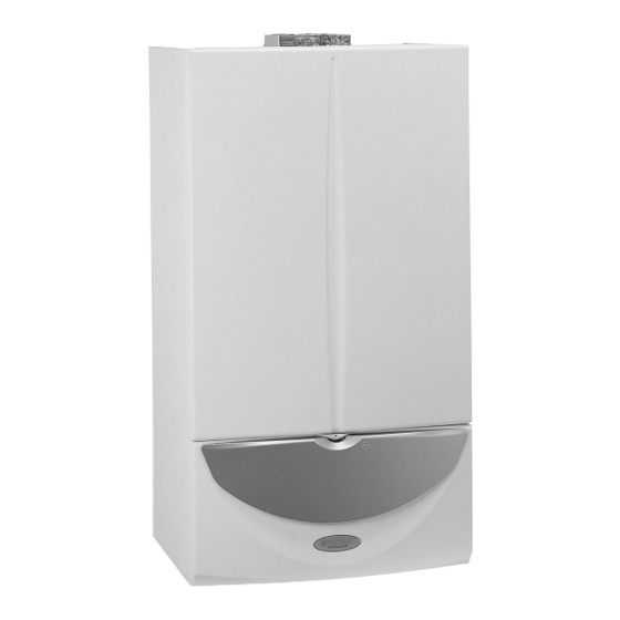
EOLO Eco Kw is a room-sealed, fan-assisted wall-mounted
generator characterised by low polluting emissions that con-
form with the requirements of the most ecological class (class
5) established by European standards (UNI EN 297 and EN
483).
ese results are possible thanks to the special water cooled
vertical Venturi burner.
ere are two versions in the range, one with a power of 24
kW (20,640 kcal/h) and one with a power of 28 kW (24,080
kcal/h).
e regulation and the control functions are managed by an
electronic control board microprocessor drive.
anks to which the appliance can be connected to the Amico
Remote Control.
e boiler features a standard antifreeze safety device that
protects it against temperatures as low as -5°C (optional as
low as -15°C).
e hydraulic circuit features a copper water-gas
exchanger as well as a new hydraulic unit in a compound
material.
Besides the pump and 3-way electric diverter valve, that,
depending on needs, lets boiler water circulate in the central
heating system or in a stainless steel plate exchanger for the
instant production of domestic hot water, this unit also
houses the devices that control the hydraulic circuit (system
absolute pressure switch, system adjustable by-pass, etc.).
Combustion air flow into the sealed chamber and flue
extraction are ensured by a fan; the correct operation of
which is controlled by a differential pressure switch.
STEEkW ed 12/03
Technical Documentation
Instantaneous wall-hung room-sealed fan-
assisted boiler with low emission of polluting
gases
EOLO Eco 24 kW
EOLO Eco 28 kW
e boiler functioning parameters are set by turning the control
panel knobs.
e functioning status and possible anomalies are easily signal-
led by leds on the panel.
1
EOLO Eco kW
Advertisement
Table of Contents

Related Manuals for Immergas EOLO Eco Series


Summary of Contents for Immergas EOLO Eco Series
- Page 1 Technical Documentation Technical Documentation EOLO Eco 24-28 kW Instantaneous wall-hung room-sealed fan- assisted boiler with low emission of polluting gases EOLO Eco 24 kW EOLO Eco 28 kW General features. EOLO Eco Kw is a room-sealed, fan-assisted wall-mounted e boiler functioning parameters are set by turning the control panel knobs.
- Page 2 Technical Documentation Technical Documentation EOLO Eco kW Main dimensions and connections. Legend: G - Gas supply AC - D.h.w. outlet AF - D.h.w. (cold) inlet R - System return M - System delivery V - Electrical connection Height (mm) Width (mm) Depth (mm) CONNECTIONS DOMESTIC...
- Page 3 Technical Documentation Technical Documentation EOLO Eco kW main components. Legend: 13 - Flue pressure switch 1 - Gas valve 14 - Draught diverter 2 - D.h.w. NTC probe 15 - Delivery probe 3 - D.h.w. flow switch 16 - Overheating safety thermostat 4 - D.h.w.
- Page 4 Technical Documentation Technical Documentation EOLO Eco kW hydraulic diagram. Legend: 15 - Circulator 1 - D.H.W. flow switch 16 - ree-way valve (motorized) 2 - D.H.W. NTC probe 17 - System draining cock 3 - D.H.W. heat exchanger 18 - System filling valve 4 - Gas valve 19 - Adjustable by-pass 5 - Burner...
-
Page 5: Operation
Technical Documentation Technical Documentation Primary circuit (boiler circuit). e primary circuit with relevant control and safety devices Boiler circulator (1). is triggered each time there is a request for central heating It works on the primary circuit return, located immediately or domestic hot water. - Page 6 Technical Documentation Technical Documentation Motorised 3-way diverter valve. Whenever a request is made (for domestic hot water or central heating) thanks to this 3-way electric diverter valve, working on Circulator the primary circuit return, boiler water is transferred either to delivery the heating system or to the d.h.w.
- Page 7 Technical Documentation Technical Documentation Safety devices and checks. Adjustable system by-pass (2). is device guarantees the circulation of water in the primary circuit (between delivery and return) even when it would be prevented by the high resistance of the system. It is mounted on the delivery manifold (1) and adjusted by a screw that can be accessed from the bottom of the valve sup- porting plate.
- Page 8 Technical Documentation Technical Documentation Secondary circuit (domestic hot water circuit). Operation. Running the domestic hot water causes cold water to flow Primary circuit Primary circuit through the d.h.w. flow switch (1) and, as a result, the electrical delivery return contact connected to it closes (see the electrical circuit). After this, the integrated board starts the domestic hot water priority function phase whereby the burner is ignited and, if there is an on-going central heating request, the 3-way diverter...
- Page 9 Technical Documentation Technical Documentation D.h.w. flow switch (1). Running the domestic hot water at a flow rate of at least 2.0 l/min and a dynamic pressure of 0.3 bar, the d.h.w. flow switch (1) enables the boiler to work in the domestic hot water phase.
-
Page 10: Gas Circuit
Technical Documentation Technical Documentation Gas circuit. is circuit consists of an atmospheric burner and a modulating Burner (4). gas valve that permit, respectively, the combustion of gas and e burner consists of two rows of 12 (24 kW version) and 14 the regulation of its flow rate. -
Page 11: Gas Adjustments
Technical Documentation Technical Documentation Gas adjustments. e maximum and the minimum gas pressure adjustments SIT 845 gas valve can be made on the gas valve respecting the values shown in Adjustment maximum pressure. the heat outputs table, in function of the model and the gas Run off some domestic hot water after having set its tempera- type (see technical data). -
Page 12: Flue Pressure Switch
Technical Documentation Technical Documentation Flue circuit. Operation. e products of combustion, after having hit the water-gas Flue pressure switch (6). exchanger (2), are slowed down and distributed by the plate It is located at the top inside the sealed chamber and detects, by (12) thus increasing combustion efficiency. - Page 13 Technical Documentation Technical Documentation measured by the relative pressure points located at the top of Air inlet and exhaust systems. the sealed chamber (9-10). (see air inlet and exhaust terminal instructions). When it triggers it causes a switch to close (S6) that acts on the integrated board enabling or preventing burner ignition.
-
Page 14: Air Inlet
Technical Documentation Technical Documentation Exhaust. Air inlet. e connection between the Ø 80 mm outlet pipes is realized Using the split system, connection to the air inlet pipes is by push-fitting with the respective flange (2), which seal is exactly the same as for the exhaust pipes, connecting to the 80 provided by special lip gaskets. -
Page 15: Electrical Circuit
Technical Documentation Technical Documentation Electrical circuit. ����� ������� ���� �������� ���� ������ ����� ����� ������������ E2 - Detection electrode E4 - Overheating safety thermostat ������� F1 - Line fuse F2 - Neutral fuse M1 - Circulator M20- Fan M30- Moterized 3-way diverter valve P1 - Central heating timer (optional) �������... -
Page 16: Low Voltage Circuit
Technical Documentation Technical Documentation Loads. It is powered by the integrated board following a d.h.w., central heating or antifreeze Boiler circulator request. (M1) It permits water circulation in the primary circuit. It is controlled by the integrated board’s ignition circuit that produces an electric discharge Ignition electrode between its end and the earthed electrode (dummy). - Page 17 Technical Documentation Technical Documentation It acts on the integrated board and enables boiler operation when Switching Flue pressure switch the flue are extracted correctly. If it is closed with the fan off it does not enable start of the igni- (S6) contact tion cycle.
-
Page 18: Operating With The Remote Control
Technical Documentation Technical Documentation Electrical circuit. Central heating phase. VOLTAGE HIGH VOLTAGE RELAY BOARD SUPPLY RELAY BOARD CONTROL CONTROLS-LOGIC MICROPROCESSOR ZONE CONTROL UNIT Operating with a room thermostat. and then both the gas valve coils (Y1). Burner ignition is detected by the integrated board by way of e central heating phase is enabled when the main selector the ionisation electrode (E2). - Page 19 Technical Documentation Technical Documentation Electrical circuit. Domestic hot water phase. VOLTAGE HIGH VOLTAGE RELAY BOARD SUPPLY RELAY BOARD CONTROL CONTROLS-LOGIC MICROPROCESSOR ZONE CONTROL UNIT Operation. Burner ignition is detected by the integrated board by way of e domestic hot water phase is enabled when the main selector the ionisation electrode (E2).
- Page 20 Technical Documentation Technical Documentation Integrated board. NAT-LPG FUSES D.H.W. CENTRAL MAIN SELECTOR SWITCH HEATING TRANSFORMER request relay. Inside the boiler’s panel there is an integrated microprocessor If the temperature measured by the delivery probe (B1) is be- controlled board that controls the appliance’s electrical devices low the temperature set on the control panel with the central for the linear modulation of burner output and, by means of heating temperature trimmer, the integrated board energizes...
- Page 21 Technical Documentation Technical Documentation Domestic hot water request. “Chimneysweep” request. When the d.h.w. flow switch (S4) closes, burner ignition pro- Turning the main selector switch (R10) round to the reset posi- ceeds in the same way as for the central heating phase. tion for 8 to 15 seconds, when it is released the board enables During the first few seconds from when the gas valve (Y1) was ignition of the generator and keeps it working at maximum...
- Page 22 Technical Documentation Technical Documentation Inputs. Zone control unit (CZ) It sends signals to the board concerning operating requests of zone valves or connected (external optional) external pumps (see zone control unit operation). Remote control It sends signals to the board of the SUMMER/WINTER selector switch concerning d.h.w. and central heating temperature adjustment and the central heating request (times, room (CAR) (optional) (see CAR operation)
- Page 23 Technical Documentation Technical Documentation Outputs. 230 Vac = coils Gas valve power supply It is a 230 V ac signal indicating that the main gas valve coils are energised (Y1) energised (Y1). 0 Vac = coils not energised Ignition electrode It is a high voltage signal (higher than 16 kV) that determines an electrical discharge at the (E1) ends of the ignition electrodes located on the burner.
-
Page 24: Safety Devices
Technical Documentation Technical Documentation Safety devices. e circulator (M1) and the 3-way diverter valve (M30) are turned on for 30 seconds Circulator / 3-way diverter after: valve antilock - 24 hours of inactivity with the main selector switch on SUMMER. - 3 hours of inactivity with the main selector switch on WINTER. - Page 25 Technical Documentation Technical Documentation Indications and alarms. e EOLO Eco kW boiler signals a malfunction with the flashing of one of the LEDs, from 5 to 11, coupled to the flashing of LED 1 (alternating). Operating indicators Remote display Boiler powered (Sum. or Wint. position) without a flame LED 1 ON Burner on LED 2 ON...
- Page 26 Technical Documentation Technical Documentation Programming the integrated board. e Eolo Eco kW boiler is designed for programming some For the association of the LED to the value, see the following operating parameters if wanted. tables: By modifying these parameters the boiler can be adapted to meet one’s specific requirements.
- Page 27 Technical Documentation Technical Documentation Permanent timing reduction. e boiler is fitted with an Central heating ignitions delayed due to Room thermostat electronic timer that prevents the burner igniting too frequently or Remote control requests. e boiler is set to turn on im- in the central heating phase.
- Page 28 Technical Documentation Technical Documentation D.h.w. exchanger preheating. When this function is active Relay 3 operation*. it is possible to maintain the d.h.w. exchanger at a constant Relay 3 operation LED flashing temperature of 50 °in order to have a quicker supply of do- (single, free contacts) (slow) mestic hot water.
- Page 29 Technical Documentation Technical Documentation EOLO Eco kW operating sequence. Central heating phase Domestic hot water phase Power on Power on Main selector switch on WINTER Main selector switch on SUMMER or WINTER ò ò Integrated board operation enabled Integrated board operation enabled Closing of the main selector switch contacts (WINTER position) Closing of the main selector switch contacts (SUMMER position) enables operation in the central heating phase...
- Page 30 Technical Documentation Technical Documentation Technical data. EOLO Eco 24 kW technical data. Nominal heat input kW (kcal/h) 25.8 (22215) Minimum heat output kW (kcal/h) 10.4 (8975) Nominal heat output (working) kW (kcal/h) 24.0 (20640) Minimum heat output (working) kW (kcal/h) 9.3 (8000) Working heat performance at nominal output 92.9...
- Page 31 Technical Documentation Technical Documentation EOLO Eco 28 kW technical data. Nominal heat input kW (kcal/h) 30.1 (25892) Minimum heat output kW (kcal/h) 11.7 (10090) Nominal heat output (working) kW (kcal/h) 28.0 (24080) Minimum heat output (working) kW (kcal/h) 10.5 (9000) Working heat performance at nominal output 93.0 Working heat performance at 30% load of nominal output...
- Page 32 Technical Documentation Technical Documentation EOLO Eco 24 kW variable heat output. NATURAL GAS (G20) PROPANE (G31) GAS FLOW GAS FLOW HEAT HEAT NOZZLE PRESS. NOZZLE PRESS. RATE RATE OUTPUT OUTPUT BURNER BURNER BURNER BURNER (kW) (kcal/h) (mbar) (mm H (kg/h) (mbar) (mm H 24.0...