
Related Manuals for Immergas MINI NIKE 3 E


Summary of Contents for Immergas MINI NIKE 3 E
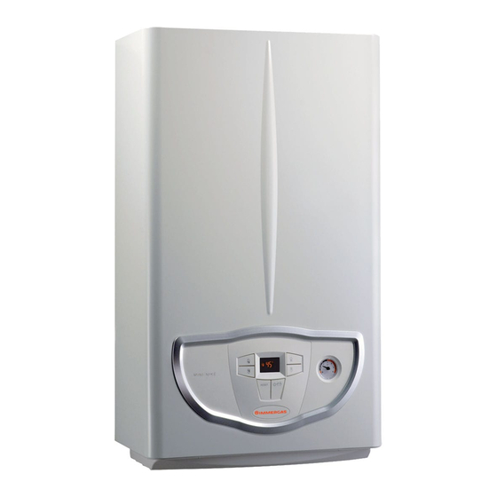
- Page 1 MINI NIKE 3 E Compact wall-hung instantaneous conventional flue boiler MINI NIKE X 3 E Compact wall-hung conventional flue boiler for central heating only or with an external storage tank...
- Page 3 (absolute system pressure switch, adjustable system by-pass, 3-bar calibrated system safety valve, etc...). A domestic water flow switch allows the boiler to be activated when domestic hot water is requested. STMiN3E ed 09/11 MINI NIKE 3 E...
- Page 4 The parameters to operate the boiler can be set via the buttons, where you can view the operating status, mode and anomalies that have occurred using a digital interface with an easy-to-read backlit display screen, located in the centre of the dashboard. STMiN3E ed 09/11 MINI NIKE 3 E...
- Page 5 G - Gas supply RU - Storage tank unit return (optional) MU - Storage tank unit flow (optional) RR - System filling R - System return M - System flow N.B.: connection group (optional) STMiN3E ed 09/11 MINI NIKE 3 E...
- Page 6 19 - System draining valve 8 - Flue safety thermostat 20 - By-pass 9 - Safety thermostat 10 - Primary heat exchanger 21 - 3 bar safety valve 11 - Flow probe N.B.: connection group (optional) STMiN3E ed 09/11 MINI NIKE 3 E...
- Page 7 6 - Flue safety thermostat 18 - By-pass 7 - Safety thermostat 8 - Primary heat exchanger 19 - 3 bar safety valve 9 - Flow probe 10 - Combustion chamber N.B.: connection group (optional) STMiN3E ed 09/11 MINI NIKE 3 E...
- Page 8 17 - Boiler in block does not require release via “Reset” temperature button 6 - Key ( ) to reduce the system water temperature 7 - Boiler manometer 8 - DHW production phase function active 9 - Boiler connected to remote control (optional) STMiN3E ed 09/11 MINI NIKE 3 E...
- Page 9 R - System return M - System flow The hot water used for central heating and domestic hot water is produced via a primary and a secondary circuit (DHW) which are affected according to necessity. STMiN3E ed 09/11 MINI NIKE 3 E...
- Page 10 RR - System filling R - System return M - System flow The primary circuit, with relative control and safety devices, is started every time there is a central heating or anti-freeze request. STMiN3E ed 09/11 MINI NIKE 3 E...
- Page 11 B = Head available to the system at maximum speed with by-pass inserted. C = Head available to the system at second speed with by-pass excluded. D = Head available to the system at second speed with by-pass inserted. STMiN3E ed 09/11 MINI NIKE 3 E...
- Page 12 It is connected to the pump flow and to the primary circuit flow using push-fitting pipes (3) with O-ring seal (5) and locked with clips (4). Flow Return STMiN3E ed 09/11 MINI NIKE 3 E...
- Page 13 (4) (DHW position). Both the spring (3) and the shutter (4) are situated inside the body of the 3-way cartridge made from composite material (2). FLOW HEAT EXCHANGER FLOW HEAT EXCHANGER FLOW SYSTEM STMiN3E ed 09/11 MINI NIKE 3 E...
- Page 14 1.0 bar. It has a rectangular shape and is positioned on the right side of the boiler next to combustion chamber and is connected to the pump unit by means of a copper pipe. STMiN3E ed 09/11 MINI NIKE 3 E...
- Page 15 CH and DHW mode (by using the optional motorised 3-way valve) The operation is conducted in the same way for combined boilers (see operation in the previous pages). FLOW HEAT EXCHANGER FLOW SYSTEM STMiN3E ed 09/11 MINI NIKE 3 E...
- Page 16 1.0 bar. It has a rectangular shape and is positioned on the right side of the boiler next to combustion chamber and is connected to the pump unit by means of a copper pipe. STMiN3E ed 09/11 MINI NIKE 3 E...
- Page 17 To replace the by-pass cartridge (5) you need to pull out the relative locking clip (6), and then pull the cartridge out from the front. N.B.: when re-mounting the by-pass cartridge body be careful not to damage the gasket. STMiN3E ed 09/11 MINI NIKE 3 E...
- Page 18 In the same way the upper part right part of the body allows DHW to flow out and the lower part allows the primary circuit to flow. Water outlet Flow Return primary circuit primary circuit STMiN3E ed 09/11 MINI NIKE 3 E...
- Page 19 The hydraulic coupling is obtained by using four gasket seals (1) that allow it to be connected directly to the domestic water inlet body and domestic water outlet body. Return Output circuit water primary domestic Flow water circuit primary STMiN3E ed 09/11 MINI NIKE 3 E...
- Page 20 COIL POWER SUPPLY RESISTANCE 230 V AC 6.25 kΩ 230 V AC 860 Ω 250mA DC (G20) Modulation coil 22 Ω 320mA DC (L.P.G.) Standard values for the boiler at maximum capacity STMiN3E ed 09/11 MINI NIKE 3 E...
- Page 21 Note: for correct ignition and detection of the boiler always respect the quotes stated in the figure here to the right. Optimal position for the electrode for correct detection STMiN3E ed 09/11 MINI NIKE 3 E...
- Page 22 1 - Coil 2 - Minimum power adjustment screws 3 - Maximum power adjustment nut 4 - Gas valve outlet pressure point 5 - Gas valve inlet pressure point 6 - Protection hood STMiN3E ed 09/11 MINI NIKE 3 E...
- Page 23 S2 - Selector switch functioning S3 - Reset block key Y1 - Gas valve S4 - Domestic hot water flow switch Y2 - Gas valve modulator S5 - System pressure switch S20 - Room thermostat (optional) STMiN3E ed 09/11 MINI NIKE 3 E...
- Page 24 (S5) is closed (pressure detected in the primary circuit higher than minimum value),the integrated P.C.B. powers the pump (M1) and the motor (M) of the 3-way valve (M30). This functions until the end run switch "3" opens STMiN3E ed 09/11 MINI NIKE 3 E...
- Page 25 65°C (fixed DHW set-point). (continuously). If during operation the CH flow probe (B1) reads a temperature above 80°C, it will be modulated by referring to the flow temperature with fixed set-point of 80°C. STMiN3E ed 09/11 MINI NIKE 3 E...
- Page 26 At every request for DHW, the burner and pump will stay off for the amount of time that has been set to allow the DHW coming from the solar storage tank to reach the boiler. STMiN3E ed 09/11 MINI NIKE 3 E...
- Page 27 Allows the passage of gas to the burner. Safety devices It cuts off the power supply to the circuit when the current absorbed Fuse exceeds 3.15A. Phase fuse (F1) 3.15 AF 250 V It is mounted onto the integrated P.C.B. STMiN3E ed 09/11 MINI NIKE 3 E...
- Page 28 If there is only little flue draught, act on the integrated P.C.B. Klixon thermostat Flue safety thermostat blocking boiler functioning for 30 minutes. with normally (E6) It is positioned on the right side of the flue hood. closed contact STMiN3E ed 09/11 MINI NIKE 3 E...
- Page 29 See How CAR remote control Version 2 acts as weekly chrono-thermostat. operates If the CAR is installed the pre-existing X40 jumper must be (CAR ) (optional) eliminated. STMiN3E ed 09/11 MINI NIKE 3 E...
- Page 30 CH NTC flow probe (B1) detects an Insufficient circulation increase in the temperature exceeding 5 °C per second (for more than 2 consecutive seconds), the burner is switched off. Re-start takes place when the flow temperature falls below 43°C. STMiN3E ed 09/11 MINI NIKE 3 E...
- Page 31 The breakage of the DHW outlet probe (B2) is signalled by the relative anomaly, (06 for Breakage of the NTC instant boilers and 12 for boilers with a storage tank) but nevertheless allows it to operate in DHW probe (B2) DHW and CH mode. STMiN3E ed 09/11 MINI NIKE 3 E...
- Page 32 ) down for 8 seconds the boiler will go into Off status. In this status the P.C.B. is fully deactivated, including the safety features. To go back to Stand-by you need to press general button 2 STMiN3E ed 09/11 MINI NIKE 3 E...
- Page 33 0 OFF 1: The boiler turns off at the Set-point, the boiler turns off at the Set-point -3K. 1 OFF 2: The boiler turns off at the Set-point, the boiler turns off at the Set-point -10K. STMiN3E ed 09/11 MINI NIKE 3 E...
- Page 34 - nG - Ci of gas lG - LPG being used Ci – Industrial gas Functional, This establishes the boiler's ignition output. Ignition power 0 - 50 % as per the final test STMiN3E ed 09/11 MINI NIKE 3 E...
-
Page 35: Table Of Contents
ERR 27 Loss of remote control communication ERR 31 / CM Low power supply voltage Not displayed Loss of flame signal Not displayed Block due to loss of continuous flame signal Not displayed STMiN3E ed 09/11 MINI NIKE 3 E... - Page 36 2 bar and an inlet temperature standards. of 15°C; the values are measured directly at the boiler outlet considering that to obtain the data declared mixing with cold water is necessary. STMiN3E ed 09/11 MINI NIKE 3 E...
- Page 37 10 - 60 ** Min. pressure (dynamic) domestic hot water circuit ** Domestic hot water circuit max. working pressure *Specific capacity “D” UB Immergas 80 l (∆T 30°C) according to EN 625 l/min 20.7 *Specific capacity “D” UB Immergas 105 l (∆T 30°C) according to EN 625 l/min 24.4...
- Page 38 0.85 7.05 71.9 0.90 2.39 24.4 8084 1.15 2.51 25.6 0.86 5.41 55.2 0.85 6.92 70.6 0.89 2.34 23.9 6020 D.H.W. 0.88 1.60 16.3 0.65 3.30 33.7 0.64 4.20 42.8 0.68 1.30 13.3 STMiN3E ed 09/11 MINI NIKE 3 E...
- Page 39 Additional system expansion vessel kit (2 litres) Polyphosphate dispenser kit code 3.018433 code 3.016305 Separate storage tank unit coupling kit Wall-mounted connection unit kit (only for MINI NIKE X 24) code 3.015229 code 3.020934 STMiN3E ed 09/11 MINI NIKE 3 E...
- Page 40 (wait for the P.C.B. to make 2 ignition cycles). The ignition electrodes discharge. The error 02 appears on the display. See error section 02 - a The error 03 appears on the display. See error section 03 - a STMiN3E ed 09/11 MINI NIKE 3 E...
- Page 41 (see technical data, The central heating request is satisfied. output, flow rate, ∆T); - the plate heat exchanger is clean and replace it, if necessary. The domestic hot water request is satisfied. STMiN3E ed 09/11 MINI NIKE 3 E...
-
Page 42: No Ignition Block
"P8" parameter); - the correct functioning of any thermostatic valves. The NTC flow probe is OK (10 kΩ at 25°C). Replace NTC probe. Check/clean/replace the main heat exchanger. STMiN3E ed 09/11 MINI NIKE 3 E... -
Page 43: Flue Safety Thermostat Anomaly
The wiring between the storage tank probe and the board (connector Restore the electric connection/replace the wiring. X2 terminals 6-7) is OK. Replace the storage tank NTC probe. If the anomaly persists, replace the P.C.B. STMiN3E ed 09/11 MINI NIKE 3 E... -
Page 44: Configuration Error
The Remote Control is connected correctly. Check the connection between P.C.B. (clamps 40-41) and remote control N.B.: only remote controls supplied by Immergas can be used (CAR (IN+ and IN-) carried out respecting the polarity and using a dedicated line to prevent interference. -
Page 45: Low Power Supply Voltage
Block due to loss of continuous flame signal. This will be displayed if error 38 occurs 6 times in 8.5 minutes. To eliminate the block, the Reset button (5) must be pressed. See Error 38. STMiN3E ed 09/11 MINI NIKE 3 E... - Page 46 - with the help of the single wire wiring diagram, use a tester to check that there is no voltage on either power supply cables of the gas valve main coils (see gas circuit chapter). STMiN3E ed 09/11 MINI NIKE 3 E...
- Page 47 The flow switch functions correctly. Check/clean/replace the flow switch. The wiring between the flow switch and the board is OK. Restore the electric connection/replace the wiring. Replace the P.C.B. STMiN3E ed 09/11 MINI NIKE 3 E...