Dyson AB 09 Service Manual
Hide thumbs
Also See for AB 09:
- Installation manual (82 pages) ,
- Owner's manual (61 pages) ,
- Manual (39 pages)
Advertisement
Quick Links
Advertisement

Related Manuals for Dyson AB 09


Summary of Contents for Dyson AB 09
- Page 1 Service manual Issued July 13...
- Page 2 AB09/10/11 hand dryer. Failure to accurately follow the instructions may result in the incorrect operation or repair of the product, damage to property and/or personal injury. Dyson will not be held liable for any damage to property or personal injury as a result of failure to comply with the instructions contained herein.
- Page 3 LOCATION • The unit is designed for dry, internal location only. • Consult local and national accessibility codes and regulations for relevant installation guidelines. Conformity and compliance is the responsibility of the installer. • Ensure the required electrical and mixed feed water supplies is available for later connection. •...
- Page 4 The following table summarises a number of potential failures, and recommended solutions to resolve them. Symptom Likely fault Solution (in order) See section No water, reduced 1. Ensure mains water water flow. Air supply to the product working. is switched on. 4 (page 21) 2.
- Page 5 Symptom Likely fault Solution (in order) See section 4 (page 21) Machine switching 1. PCB assy (Tap) •Check PCB assy (Tap) for alignment on intermittently - failure. function. Replace if necessary. 4 (page 21) water and air. 2. Lens housing assy •Check Lens housing assy is clean.
-
Page 6: Section 1 Solenoid Assembly Removal
Section 1 Solenoid assembly removal... - Page 7 Section 1 Solenoid assembly removal Warning: before continuing ensure the power and water supplies to the the machine are switched off. 01 Using a small flat bladed screwdriver, unclip and remove the HEPA filter from the base of the Motorbucket. 02 In some cases a T-15 screw may have been fitted into the Motorbucket release button.
- Page 8 Section 1 Solenoid assembly fitting...
- Page 10 Section 1 Solenoid assembly fitting 10 Push the water pipe as far as possible onto the new Solenoid. 11 Clip the solenoid into the Backplate. 12 Connect the Solenoid to the Solenoid to PCB loom. 13 Locate the water pipe clip onto the end of the water pipe and fasten into place. Fit the two Phillips screws.
-
Page 11: Section 2 Air Hose/Tap Assembly Removal
Section 2 Air hose/Tap assembly removal Before continuing please follow steps 1-3 and 5-6 of Section 1 of this manual. AB09/10 only AB11 only AB11 only... -
Page 12: All Models
AB11 only All models AB11 only All models AB09/10 only... -
Page 13: Section 2 Power Supply Assembly Removal
Section 2 Power supply assembly removal Before continuing please follow steps 1-3 and 5 of Section 1 of this manual. Communications PCB loom assembly... - Page 14 Section 2 Air hose/Tap/Power supply assembly removal Warning: before continuing ensure the power and water supplies to the the machine are switched off. Air hose/Tap assembly removal Before continuing please follow steps 1-3 and 5-6 of Section 1 of this manual. All models: 01 Remove the six T-15 screws in the electrical cover.
- Page 15 Section 2 Power supply assembly fitting After fitting the Electrical cover, the existing parts should be fitted as previously shown (page 8, steps 16-18).
- Page 16 Air hose/Tap assembly fitting AB09/10 only All models AB11 only AB11 only AB11 only AB11 only...
- Page 17 After fitting the Electrical cover, the existing parts should be fitted as previously shown (page 8, steps 16-18).
- Page 18 Section 2 Air hose/Tap/Power supply assembly fitting Power supply assembly fitting 01 Slide the new Power supply assembly into place. 02 Tilt the Power supply underneath the communications cable and locate into the Backplate. Ensure the female connector block clicks into place. Fit the T-10 screw into the centre of the PCB and the T-15 screw into the connector block.
-
Page 19: Section 3 Backplate Replacement Removal
Section 3 Backplate replacement removal Before continuing the following parts need to be removed as previously shown: the Solenoid assembly (pages 5-6), and the Air Hose and Power supply assemblies (pages 10-13). - Page 20 Section 3 Backplate replacement fitting...
- Page 21 Section 3 Backplate replacement removal Warning: before continuing ensure the power and water supplies to the the machine are switched off. Before continuing the following parts need to be removed as previously shown: the Solenoid assembly (pages 5-6), and the Air Hose and Power supply assemblies (pages 10-13). 01 Carefully release the grommet holding the Comms to PCB loom assembly.
-
Page 22: Section 4 Internals Of Tap Replacement Removal
Section 4 Internals of Tap replacement removal... - Page 25 Section 4 Internals of Tap replacement removal Warning: before continuing ensure the power and water supplies to the the machine are switched off. 01 Insert a 1.5mm or 1/16 Allen key into the small hole in the underside of the tap. Note: it will be necessary to force the Allen key through a rubber sleeve and into the grub screw.
- Page 26 Section 4 Internals of Tap replacement fitting...
- Page 29 Gel seal EPDM seal...
- Page 30 Section 4 Internals of Tap replacement fitting Note: it is advisable to remove the Tap from it’s location prior to fitting the internal components. 01 Remove the nut from the Tap stem. Remove the Tap. 02 Feed the Comms cable through the Water pipe assembly housing. 03 Locate the Comms cable into the Water pipe assembly housing ensuring the outer insulation is securely fitted in all three grip details.
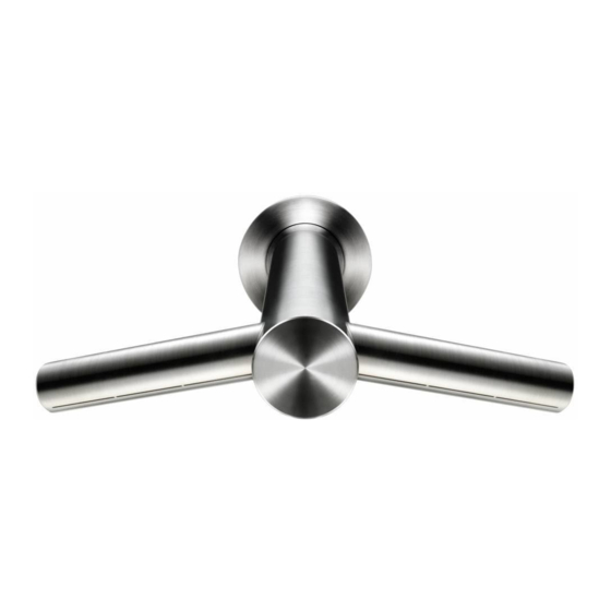
- Page 31 Tap assembly AB09 Tap Assy Comms Loom Assy Water Pipe Service Assy O-Ring Aerator Housing Thermal Insulating Foam Lens Housing Assy PCB Housing Inner Screw Glamour Cap Service Assy PCB Housing Outer PCB Assy Air Hose (Tap) Assy Grub Screw Accessory Pack Assy Aerator Service...
- Page 32 Tap assembly AB10 Tap Assy Comms Loom Assy Water Pipe Service Assy O-Ring Aerator Housing Thermal Insulating Foam Lens Housing Assy PCB Housing Inner Screw Glamour Cap Service Assy PCB Housing Outer PCB Assy Air Hose (Tap) Assy Grub Screw Accessory Pack Assy Aerator Service...
- Page 33 Tap assembly AB11 Tap Assy Comms Loom Assy Water Pipe Service Assy O-Ring Aerator Housing Thermal Insulating Foam Lens Housing Assy PCB Housing Inner Screw Glamour Cap Service Assy PCB Housing Outer PCB Assy Air Hose (Tap) Assy Grub Screw Accessory Pack Assy Aerator Service...
-
Page 34: Backplate Assembly
Backplate assembly Backplate Service Assy Comms to PCB Loom Assy Solenoid Service Assy Screw Screw Power Supply Assy Screw Screw Solenoid to PCB Loom Assy Screw... - Page 35 Motorbucket assembly Motor & Bucket Service Assy Filter Cage Service Assy...
- Page 36 Metal enclosure assembly Metal Enclosure Assembly Grommet-Water Grommet-Power Air Vent Cover...
- Page 37 AB09 10 11 Wiring schematic...