
Related Manuals for HP TBD


Summary of Contents for HP TBD
- Page 1 Maintenance and Service Guide SUMMARY This guide provides information about spare parts, removal and replacement of parts, security, backing up, and more.
- Page 2 Chromebook, Chrome OS, Google, and Google of the HP End User License Agreement (EULA). If To access the latest user guides, go to Drive are trademarks of Google LLC. Intel, you do not accept these license terms, your sole http://www.hp.com/support, and follow the...
- Page 3 Safety warning notice Reduce the possibility of heat-related injuries or of overheating the computer by following the practices described. WARNING! To reduce the possibility of heat-related injuries or of overheating the computer, do not place the computer directly on your lap or obstruct the computer air vents. Use the computer only on a hard, flat surface. Do not allow another hard surface, such as an adjoining optional printer, or a soft surface, such as pillows or rugs or clothing, to block airflow.
- Page 4 Important notice about Customer Self-Repair parts Your computer includes Customer Self-Repair parts and parts that should be accessed by only an authorized service provider. IMPORTANT: See "Removal and replacement procedures for Customer Self-Repair parts" for details. Accessing parts described in "Removal and replacement procedures for authorized service provider parts" can damage the computer or void your warranty.
-
Page 5: Table Of Contents
Generating static electricity ..............................23 Preventing electrostatic damage to equipment........................24 Personal grounding methods and equipment ........................24 Grounding the work area................................25 Recommended materials and equipment..........................25 Cleaning your computer ..................................26 Enabling HP Easy Clean (select products only)........................26... - Page 6 Removing dirt and debris from your computer........................26 Cleaning your computer with a disinfectant .......................... 27 Caring for wood veneer (select products only)........................28 Packaging and transporting guidelines ............................28 Accessing support information ................................. 28 5 Removal and replacement procedures for authorized service provider parts ................31 Component replacement procedures ..............................
- Page 7 Index..........................................70...
-
Page 8: Product Description
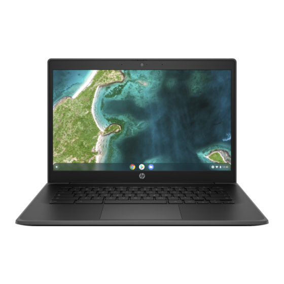
Product components and their descriptions Category Description Product Name HP Fortis 14 inch G10 Chromebook Model number: TBD CTO model number: TBD Processors Intel® Pentium™ Silver N6000 (1.1 GHz) processor (4 cores, 2933 MHz front side bus [FSB], 4 MB level 3 ●... - Page 9 Island style, non-backlit, spill-resistant keyboard in jet black finish devices Power requirements 2 cell, 47 Whr battery (polymer, HP Long Life, with HP Fast Charge Technology) 45 W AC adapter (non-Power Factor Correction (nPFC), standard USB Type-C, 1.8 m [6.0 ft], with straight connector) C5, 1.0 m (3.3 ft) power cord...
-
Page 10: Components
Components Your computer features top-rated components. This chapter provides details about your components, where they are located, and how they work. Right Use the illustration and table to identify the components on the right side of the computer. Table 2-1 Right-side components and their descriptions Component Description... -
Page 11: Left
Table 2-1 Right-side components and their descriptions (continued) Component Description Off: The battery is not charging. ● USB Type-C® power connector and Connects an AC adapter that has a USB Type-C connector, SuperSpeed port supplying power to the computer and, if needed, charging the computer battery. -
Page 12: Display
Table 2-2 Left-side components and their descriptions (continued) Component Description USB SuperSpeed port Connects a USB device, such as a cell phone, camera, activity tracker, or smartwatch, and provides high-speed data transfer. SIM card slot Supports a wireless SIM card. Display Use the illustration and table to identify the components on the display. -
Page 13: Keyboard Area
Table 2-3 Display components and their descriptions (continued) Component Description Off: The camera is turned off by the software. *The antennas are not visible from the outside of the computer. For optimal transmission, keep the areas immediately around the antennas free from obstructions. For wireless regulatory notices, see the section of the Regulatory, Safety, and Environmental Notices that applies to your country or region. -
Page 14: Special Keys
Table 2-5 Speakers and power key and their descriptions Component Description Speakers Produce sound. Power key When the computer is off, press the key briefly to turn on the ● computer. When the computer is on, press and hold the key for 10 ●... -
Page 15: Labels
Table 2-6 Special keys and their descriptions Component Description Activates certain computer functions when pressed in combination with other keys, such as or shift. Search key Press to search your apps and the web from your apps list. Action keys Execute frequently used system functions. - Page 16 Table 2-7 Service label components and their descriptions Component Serial number Product ID HP product name Table 2-8 Service label components and their descriptions Component HP product name Product ID Serial number Warranty period Table 2-9 Service label components and their descriptions...
- Page 17 Table 2-9 Service label components and their descriptions (continued) Component Serial number Regulatory labels—Provide regulatory information about the computer. ● Wireless certification labels—Provide information about optional wireless devices and the approval markings ● for the countries or regions in which the devices have been approved for use. Chapter 2 Components...
-
Page 18: Illustrated Parts Catalog
To identify the computer major components, use this illustration and table. NOTE: HP continually improves and changes product parts. For complete and current information about supported parts for your computer, go to http://partsurfer.hp.com, select your country or region, and then follow the on-screen instructions. NOTE: Details about your computer, including model, serial number, product key, and length of warranty, are on the service tag at the bottom of your computer. - Page 19 Table 3-1 Computer major component descriptions and part numbers Item Component Spare part number Display assembly NOTE: Display spare parts are available as subcomponents, not as whole units. Display subcomponent spare parts are available. For spare part information, see Display assembly subcomponents on page (2a) Top cover/keyboard in jet black finish for use on computer models equipped with WWAN capability: For use in Belgium...
- Page 20 Table 3-1 Computer major component descriptions and part numbers (continued) Item Component Spare part number For use in France N01976-051 For use in French Canada N01976-DB1 For use in Germany N01976-041 For use in Greece N01976-151 For use in Iceland N01976-DD1 For use in India N01976-D61...
- Page 21 Table 3-1 Computer major component descriptions and part numbers (continued) Item Component Spare part number For use in Iceland N01977-DD1 For use in India N01977-D61 For use in Israel N01977-BB1 For use in Italy N01977-061 For use in Japan N01977-291 For use in Latin America N01977-161 For use in the Netherlands...
- Page 22 Table 3-1 Computer major component descriptions and part numbers (continued) Item Component Spare part number (4c) Connector board high-speed cable (included in the Cable Kit, spare part number N02955-001) (4d) Connector board I/O bracket (included in the Bracket Kit, spare part number N01962-001) (5a) Sensor board N01958-001...
-
Page 23: Display Assembly Subcomponents
Table 3-1 Computer major component descriptions and part numbers (continued) Item Component Spare part number Equipped with an Intel Celeron N4500 (1.1 GHz) processor (2933 MHz FSB, 4 MB L3 cache, 6 W), 8 GB N01945-001 of system memory, and 64 GB of eMMC system storage Equipped with an Intel Celeron N4500 (1.1 GHz) processor (2933 MHz FSB, 4 MB L3 cache, 6 W), 4 GB N01943-001 of system memory, and 32 GB of eMMC system storage... - Page 24 Table 3-2 Display component descriptions and part numbers Item Component Spare part number Display bezel N01971-001 Display hinges (includes left and right hinges) N01974-001 35.6 cm (14.0 in) display panel: Display panel for use only on computer models equipped with WWAN capability: LCD, FHD (1920 ×...
-
Page 25: Brackets
Table 3-2 Display component descriptions and part numbers (continued) Item Component Spare part number LCD, HD (1366 × 768), LED, antiglare, SVA, 45 % CG, eDP 1.2 without PSR, flat touchscreen display N01955-001 panel with narrow bezel and camera privacy cover; typical brightness: 250 nits LCD, FHD (1920 ×... -
Page 26: Cables
Table 3-3 Bracket descriptions and part numbers Item Component The brackets listed below are included in the Bracket Kit, spare part number N01962-001. Connector board I/O bracket Display hinge left bracket Display hinge right bracket Display panel bracket Security cable lock bracket System board I/O bracket Touchpad bracket WLAN module bracket... -
Page 27: Miscellaneous Parts
Table 3-4 Cable descriptions and part numbers Item Component The cables listed below are included in the Cable Kit, spare part number N02955-001. Connector board high-speed cable Connector board low-speed cable Sensor board cable Touchpad cable SIM cable Miscellaneous parts To identify the miscellaneous parts, use this table. - Page 28 Table 3-5 Miscellaneous part descriptions and part numbers (continued) Component Spare part number For use in Europe L19361-001 For use in India L19363-001 For use in Israel L19362-001 For use in Italy L19364-001 For use in Japan L19365-001 For use in North America L19367-001 For use in South Africa L19369-001...
-
Page 29: Removal And Replacement Procedures Preliminary Requirements
Removal and replacement procedures preliminary requirements Use this information to properly prepare to disassemble and reassemble the computer. Tools required You need the following tools to complete the removal and replacement procedures: Tweezers ● Nonconductive, nonmarking pry tool ● Magnetic Phillips P1 screwdriver ●... -
Page 30: Drive Handling
Drive handling Note the following guidelines when handling drives. IMPORTANT: Drives are fragile components. Handle them with care. To prevent damage to the computer, damage to a drive, or loss of information, observe these precautions: Before removing or inserting a hard drive, shut down the computer. If you are unsure whether the computer is off or in Hibernation, turn the computer on, and then shut it down through the operating system. -
Page 31: Preventing Electrostatic Damage To Equipment
Static electricity increases as humidity decreases. ● Table 4-1 Static electricity occurrence based on activity and humidity Relative humidity Event Walking across carpet 7,500 V 15,000 V 35,000 V Walking across vinyl floor 3,000 V 5,000 V 12,000 V Motions of bench worker 400 V 800 V 6,000 V... -
Page 32: Grounding The Work Area
Use conductive field service tools, such as cutters, screwdrivers, and vacuums. ● Avoid contact with pins, leads, or circuitry. ● Recommended materials and equipment HP recommends certain materials and equipment to prevent static electricity. Antistatic tape ● Antistatic smocks, aprons, or sleeve protectors ●... -
Page 33: Cleaning Your Computer
Enabling HP Easy Clean (select products only) HP Easy Clean helps you to avoid accidental input while you clean the computer surfaces. This software disables devices such as the keyboard, touch screen, and touchpad for a preset amount of time so that you can clean all computer surfaces. -
Page 34: Cleaning Your Computer With A Disinfectant
Keep liquids away from the product. Avoid getting moisture in any openings. If liquid makes its way inside your HP product, it can cause damage to the product. Do not spray liquids directly on the product. Do not use aerosol sprays, solvents, abrasives, or cleaners containing hydrogen peroxide or bleach that might damage the finish. -
Page 35: Caring For Wood Veneer (Select Products Only)
When grounding is not possible, use an ionizer to dissipate electric charges. Accessing support information Use this information to find the HP support that you need. Chapter 4 Removal and replacement procedures preliminary requirements... - Page 36 Search collect Chrome device logs. Technical bulletins To locate technical bulletins: Go to www.hp.com. Place the cursor over Problem solving to display more options. Select Support & Troubleshooting. Type the serial number, product number, or product name to go to the product support page.
- Page 37 Table 4-3 Support information locations (continued) Service consideration Path to access information Near the bottom of the window, select Notebook PCs, and then select your location. Chapter 4 Removal and replacement procedures preliminary requirements...
-
Page 38: Removal And Replacement Procedures For Authorized Service Provider Parts
NOTE: HP continually improves and changes product parts. For complete and current information about supported parts for your computer, go to http://partsurfer.hp.com, select your country or region, and then follow the on-screen instructions. You must remove, replace, or loosen as many as 59 screws when you service the parts described in this chapter. - Page 39 Table 5-1 Bottom cover description and part number Description Spare part number Bottom cover N01965-001 Before removing the bottom cover, prepare the computer for disassembly (see Preparation for disassembly on page 31). Remove the bottom cover: Remove the two Phillips M2.5 × 8.6 screws (1) that secure the bottom cover to the computer. Loosen the three captive Phillips M2.5 ×...
-
Page 40: Battery
Remove the bottom cover (3). To replace the bottom cover, reverse the removal procedures. Battery To remove the battery, use this procedure and illustration. Table 5-2 Battery description and part number Description Spare part number Battery (2 cell, 47 Whr, Li-ion, includes cable) M25914-005 WARNING! To avoid personal injury and damage to the product:... -
Page 41: Wwan Module
WARNING! To reduce potential safety issues, use only the user-replaceable battery provided with the computer, a replacement battery provided by HP, or a compatible battery purchased from HP. IMPORTANT: Removing a battery that is the sole power source for the computer can cause loss of information. - Page 42 Remove the WWAN module: Remove the Phillips M2.0 × 3.4 screw (1) that secures the WWAN module to the system board. (The WWAN module tilts up.) Remove the WWAN module bracket (2). The WWAN module bracket is included in the Bracket Kit, spare part number N01962-001. Disconnect the WWAN antenna cables (3) from the terminals on the WWAN module.
-
Page 43: Wlan Module
If the WWAN antenna is not connected to the terminal on the WWAN module, you must install a protective sleeve on the antenna connector, as shown in the following illustration. Reverse this procedure to install the WWAN module. WLAN module To remove the WLAN module, use this procedure and illustration. -
Page 44: Sim Cable (Select Products Only)
Disconnect the WLAN antenna cables (3) from the terminals on the WLAN module. NOTE: Models have either one or two WLAN antennas. On models with two antennas, the #1 white WLAN antenna cable connects to the WLAN module #1 Main terminal. The #2 black WLAN antenna cable connects to the WLAN module #2 Aux terminal. -
Page 45: Sensor Board Cable
NOTE: The SIM cable is included in the Cable Kit, spare part number N02955-001. Before removing the SIM cable, follow these steps: Prepare the computer for disassembly (see Preparation for disassembly on page 31). Remove the bottom cover (see Battery on page 33). -
Page 46: Sensor Board
Remove the sensor board cable: Release the ZIF connector (1) to which the sensor board cable is connected, and then disconnect the sensor board cable from the connector board. Release the ZIF connector (2) to which the sensor board cable is connected, and then disconnect the sensor board cable from the sensor board. -
Page 47: Connector Board Cables
Remove the sensor board (2). Reverse this procedure to install the sensor board. Connector board cables To remove the connector board cables, use this procedure and illustration. NOTE: The connector board cables are included in the Cable Kit, spare part number N02955-001. Before removing the connector board cables, follow these steps: Prepare the computer for disassembly (see Preparation for disassembly on page... -
Page 48: Connector Board
Remove the connector board cables (3). Reverse this procedure to install the connector board cables. Connector board To remove the connector board, use this procedure and illustration. Table 5-6 Connector board description and part number Description Spare part number For use on computer models equipped with WWAN capability N01957-001 For use on computer models equipped without WWAN capability N01956-001... - Page 49 Release the ZIF connector (2) to which the sensor board cable is connected, and then disconnect the sensor board cable from the connector board. Remove the two Phillips M2.0 × 5.2 screws (1) that secure the connector board and I/O bracket to the computer.
-
Page 50: Speakers
Speakers To remove the speakers, use this procedure and illustration. Table 5-7 Speaker description and part number Description Spare part number Speaker (includes left and right speakers, cables, and two rubber isolators) N01966-001 Before removing the speakers, follow these steps: Prepare the computer for disassembly (see Preparation for disassembly on page 31). - Page 51 Table 5-8 System board descriptions and part numbers Description Spare part number System board: The system board spare part kit includes an integrated processor, UMA graphics subsystem memory, system memory, system storage, the Google Chrome operating system, and replacement thermal material. Replacement thermal material is also available using spare part number N01960-001.
- Page 52 Release the adhesive support strip (1) that secures the display panel cable to the system board. Release the connector bar (2) that secures the display panel cable to the system board. Disconnect the display panel cable (3) from the system board. Disconnect the following cables from the system board: Power cable (ZIF) (4) ●...
-
Page 53: Heat Sink
Lift the right side of the system board (1) until it rests at an angle. Slide the system board (2) up and to the right at an angle to remove it. Reverse this procedure to install the system board. Heat sink To remove the heat sink, use these procedures and illustrations. - Page 54 Prepare the computer for disassembly (see Preparation for disassembly on page 31). Remove the bottom cover (see Battery on page 33). Disconnect the battery cable from the system board (see Battery on page 33). Remove the WLAN module (see WLAN module on page 36).
-
Page 55: Display Assembly
Reverse this procedure to install the heat sink. Display assembly To remove and disassemble the display assembly, use these procedures and illustrations. Full hinge-up displays are not available as spare parts. Spare parts for displays are available only at the subcomponent level. - Page 56 Disconnect the WLAN antenna cables (5) from the terminals on the WLAN module. NOTE: Models have either one or two WLAN antennas. On models with two antennas, the #1 white WLAN antenna cable connects to the WLAN module #1 Main terminal. The #2 black WLAN antenna cable connects to the WLAN module #2 Aux terminal.
- Page 57 Open the display assembly (2) as far as it will open. Separate the computer (3) from the display assembly. If the security cable lock bracket becomes dislodged from the top cover/keyboard during the display assembly removal process, install it in the top cover/keyboard as shown in the following illustration. The security cable lock bracket is included in the Bracket Kit, spare part number N01962-001.
- Page 58 The bezel is available using spare part number N01971-001. If you need to remove the hinges: Remove the display bezel. Remove the eight Phillips M2.5 × 2.5 broadhead screws (1) that secure the hinges to the display back cover. Remove the two Phillips M2.5 × 2.4 screws (2) that secure the hinges to the display back cover. Remove the display hinges (3).
- Page 59 The display panel is secured to the display back cover with tape that is installed under the left (1) and right sides of the panel. To remove the panel, use tweezers to grasp the end of the tape (2). While turning the tweezers, wrap the tape around the tweezers as you continue to pull the tape out (3) from behind the display panel.
- Page 60 Disconnect the display panel cable (5) from the display panel. Remove the display panel. The display panel is available using the following spare part numbers: N01953-001: LCD, FHD (1920 × 1080), WLED, antiglare, UWVA, 45 % CG, eDP, slim touchscreen display panel with narrow bezel and camera privacy cover;...
- Page 61 Detach the webcam/microphone module cable (1) from the display back cover. (The webcam/ microphone module cable is attached to the display back cover with double-sided tape.) Detach the webcam/microphone module (2) from the display back cover. (The webcam/microphone module is attached to the display back cover with double-sided tape.) Chapter 5 Removal and replacement procedures for authorized service provider parts...
- Page 62 Release the ZIF connector (1) to which the webcam/microphone module cable is connected, and then disconnect the webcam/microphone module cable (2) from the webcam/microphone module. The webcam/microphone module is available using spare part number N01972-001. The webcam/ microphone module cable is a component of the display panel cable. If you need to remove the WLAN antenna and transceivers: Remove the display bezel.
-
Page 63: Touchpad Cable
If you need to remove the WWAN antenna and transceivers: Remove the display bezel. Remove the display hinges. Remove the display panel. Remove the webcam/microphone module. Release the retention tabs (1) that secure the WWAN antenna cables to the display back cover. Detach the WWAN antenna transceivers (2) from the display back cover. -
Page 64: Touchpad
Release the ZIF connector (2) to which the touchpad cable is connected, and then disconnect the power cable from the touchpad. Detach the touchpad cable (3) from the computer. (The touchpad cable is attached to the computer with double-sided adhesive.) Remove the touchpad cable. -
Page 65: Keyboard With Top Cover
Remove the touchpad bracket (2). The touchpad bracket is included in the Bracket Kit, spare part number N01962-001. Remove the touchpad (3). Reverse this procedure to install the touchpad. Keyboard with top cover The top cover with keyboard remains after removing all other spare parts from the computer. In this section, the first table provides the main spare part number for the top cover/keyboards. - Page 66 Table 5-12 Spare part country codes (continued) For use in country or region Spare part For use in country or region Spare part For use in country or region Spare part number number number France -051 Portugal -131 Turkey -141 Germany -041 Romania...
-
Page 67: Backing Up, Resetting, And Recovering
Backing up, resetting, and recovering This chapter provides information about processes that are standard procedure for most products. Backing up You can back up your data to an optional USB flash drive or SD memory card or through Google Drive. For detailed information about creating a backup, go to http://www.support.google.com. -
Page 68: Recovering
Once you complete the reset, you can set up your computer and check to see whether the problem is fixed. Recovering When your Chrome OS™ operating system is not working properly, you can perform a recovery. A recovery reinstalls the operating system and software programs and restores the original factory settings. Locally saved files and saved networks are deleted for all accounts. -
Page 69: Recovering The Chrome Operating System
Recovering the Chrome operating system To recover the Chrome operating system on your computer using the recovery media you created: Disconnect any external devices connected to your computer, plug in the power cord, and then turn on the computer. To enter recovery mode, press and hold + f3, and then press the power button. -
Page 70: Specifications
Specifications This chapter provides specifications for your computer. Computer specifications This section provides specifications for your computer. When you travel with your computer, the computer dimensions and weights, as well as input power ratings and operating specifications, provide helpful information. Table 7-1 Computer specifications Metric... -
Page 71: 35.6 Cm (14.0 In) Display Specifications
Table 7-1 Computer specifications (continued) Metric U.S. Nonoperating –15 m to 12,192 m –50 ft to 40,000 ft NOTE: Applicable product safety standards specify thermal limits for plastic surfaces. The device operates well within this range of temperatures. 35.6 cm (14.0 in) display specifications This section provides specifications for your display. -
Page 72: Statement Of Memory Volatility
No applications, features, or functionality were added to or installed on the system. ● Following system shutdown and removal of all power sources from an HP business computer system, personal data can remain on volatile system memory (DIMMs) for a finite period of time and also remains in nonvolatile memory. -
Page 73: Power Cord Set Requirements
Power cord set requirements This chapter provides power cord requirements for countries and regions. The wide-range input feature of the computer permits it to operate from any line voltage from 100 V ac to 120 V ac, or from 220 V ac to 240 V ac. The three-conductor power cord set included with the computer meets the requirements for use in the country or region where the equipment is purchased. - Page 74 Table 9-1 Power cord requirements for specific countries and regions (continued) Country/region Accredited agency Applicable note number Canada Chile Denmark DEMKO Finland FIMKO France Germany India Israel Italy Japan Netherlands KEMA New Zealand SANZ Norway NEMKO People's Republic of China Saudi Arabia SASO Singapore...
- Page 75 Table 9-1 Power cord requirements for specific countries and regions (continued) Country/region Accredited agency Applicable note number The flexible cord must be Type HVCTF three-conductor, 1.25 mm² conductor size. Power cord set fittings (appliance coupler, cable, and wall plug) must bear the BSMI certification mark. For 127 V ac, the flexible cord must be Type SVT or SJT 3-conductor, 18 AWG, with plug NEMA 5-15P (15 A, 125 V ac), with UL and CSA or C-UL marks.
-
Page 76: Recycling
Follow the local laws and regulations in your area for battery disposal. HP encourages customers to recycle used electronic hardware, HP original print cartridges, and rechargeable batteries. For more information about recycling programs, see the HP website at http://www.hp.com/recycle. - Page 77 14 removal 55, 56 disinfecting 27 display hinge right bracket spare part number 18 HP Easy Clean 26 illustrated 14 spare part numbers 55, 56 removing dirt and debris 26 spare part number 14 audio-in (microphone) jack,...
- Page 78 1 hinge bracket removal 49 recovering 61 spare part number 49 recovering Chrome operating nonvolatile memory 65 HP Sure Start 65 system 62 Recovery Utility 61 removal and replacement operating system, product illustrated parts catalog 11 procedures 31...
- Page 79 setting up computer after reset or recovery 62 USB SuperSpeed port, identifying 4, SIM cable illustrated 15, 19 USB Type-C power connector and removal 37 SuperSpeed port, identifying 4 spare part number 15, 19, 37 SIM card slot, identifying 5 slots video, product description 1 Security cable 4...