Table of Contents
Advertisement
Quick Links
Advertisement
Table of Contents

Related Manuals for Immergas VICTRIX R 24 1 I


Summary of Contents for Immergas VICTRIX R 24 1 I
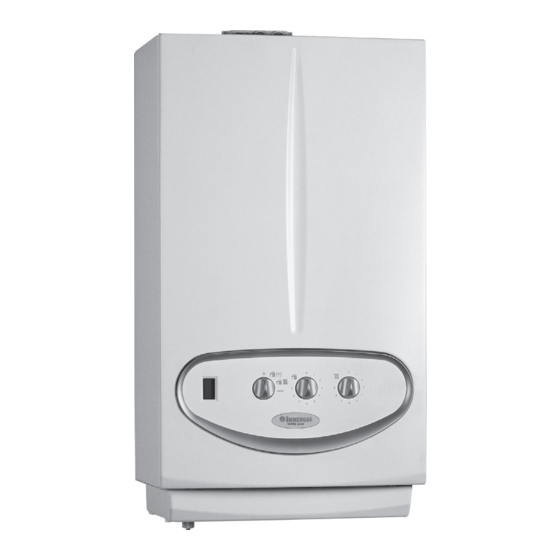
- Page 1 VICTRIX R 24 1 I Condensation wall hung boiler for central heating only...
- Page 3 VICTRIX R 24 1 I General features. VICTRIX R 24 1 I is a wall-hung sealed generator (type C) The hydraulic circuit has a water-gas heat exchanger with coil with useful heat output of 24 kW (20,640 kcal/h) for room in STAINLESS STEEL.
- Page 4 Technical Documentation Technical Documentation Main dimensions and VICTRIX R 24 1 I connections. Key: Height (mm) Width (mm) Depth (mm) V - Power supply connection G - Gas supply SC - Condensate drain (min. internal diameter Ø 13 mm) CONNECTIONS...
- Page 5 Technical Documentation Technical Documentation VICTRIX R 24 1 I control panel. Key: 1 - Boiler status signal display 2 - Stand-by selector- D.H.W./Remote Control - D.H.W. and Central Heating - Reset 3 - Domestic hot water temperature selector 4 - Central heating temperature selector...
- Page 6 Technical Documentation Technical Documentation VICTRIX R 24 1 I main components. Key: 12 - Negative sign pressure point 1 - Electric connection terminal board 13 - Positive sign pressure point (very low voltage) 14 - Sample points (air A) - (flue exhaust F)
-
Page 7: Primary Circuit
Technical Documentation Technical Documentation VICTRIX R 24 1 I hydraulic layout. Key: 1 - Condensate drain trap 2 - Gas valve 3 - Gas valve outlet pressure point (P3) 4 - Air/gas Venturi collector 5 - Fan 6 - Gas nozzle... -
Page 8: Primary Heat Exchanger
The condensate drain is also found in the lower part. To ease the escape of any air bubbles still present in the coils, there is a manual air vent in the upper part of the module RETURN (5). FLOW CONDENSATION RUNOFF STVR1I ed 04/08 VICTRIX R 24 1 I... - Page 9 The body is made of two parts in plastic, which are fixed to each other by two self-tapping screws. The flow switch (1) is push-fitted onto the system return pipe (2) and blocked by two appropriate shaped forks. RETURN FLOW STVR1I ed 04/08 VICTRIX R 24 1 I...
-
Page 10: Gas Valve
(4), where the premix starts with the combustion agent air. The mixture obtained in this way is ignited on the surface of the cylindrical burner (8) by the discharge of the ignition electrodes (9). STVR1I ed 04/08 VICTRIX R 24 1 I... - Page 11 4.7 kW (4,042 kcal/h) (20 % of the heat output). Ignition takes place by means of an integrated P.C.B. that controls the ignition (7) and detection electrodes (9). STVR1I ed 04/08 VICTRIX R 24 1 I...
- Page 12 It is fixed onto the left side of the burner flange (4). Note: In the case of ignition block, check the distances of the ignition and detection electrodes keeping to the heights stated in the figure below. IGNITER DRAWING STVR1I ed 04/08 VICTRIX R 24 1 I...
- Page 13 Loosen the tightening bolts on the system flow and return pipes positioned in the lower part of the module. Loosen the two screws (7) and (9) that fix the condensation module to the support back using brackets and sheet steel. STVR1I ed 04/08 VICTRIX R 24 1 I...
- Page 14 - calibration functions, positioning the D.H.W. adjustment STVR1I ed 04/08 VICTRIX R 24 1 I...
-
Page 15: Gas Transformation
Key: 1 - Gas valve inlet pressure point 2 - Gas valve outlet pressure point VICTRIX R 24 1 I 3 - Off-Set adjusting screw 12 - Outlet gas flow rate regulator at nominal heat... - Page 16 130 °C (max. flue temp with flow 85 °C = 78 °C). A flue safety thermostat is inserted onto the condensation module (12), to protect the flue hood (1) and which intervenes STVR1I ed 04/08 VICTRIX R 24 1 I...
- Page 17 Intake and exaust systems. (see intake and exhaust terminals instructions). The VICTRIX R 24 1 I boiler is prepared for connection to the appropriate snap-fit intake/exhaust pipes and can be installed inside the home or outside the home or outside of the home (in...
- Page 18 (see boiler instructions book). The coupling of the accessories (curves, extensions, terminals) is push-fitting type and sealing is ensured by the lip seals in EPDM peroxide resistent to the action of the condensate. STVR1I ed 04/08 VICTRIX R 24 1 I...
- Page 19 It is connected to the boiler using a concentric flange 60/100 (2) which, using extensions, is connected to the relevant intake and exhaust terminal 60 /100 (5) with aluminium tile (4). The maximum total length is 14.4 straight vertical metres. STVR1I ed 04/08 VICTRIX R 24 1 I...
- Page 20 30 straight vertical metres. Using a divided kit 80/80 (1 bend + 1 m in intake and exhaust) with intake grid, the maximum length allowed is 22 straight vertical metres. STVR1I ed 04/08 VICTRIX R 24 1 I...
-
Page 21: Electric Circuit
- Room thermostat jumper - Transformer fuse - Gas valve The VICTRIX R 24 1 I electric circuit is completely The control and safety devices operate partly at mains voltage interlocked to a P.C.B. with integrated microprocessor which (230 V AC) and partly at low voltage. - Page 22 It is powered by the integrated P.C.B. when the burner must be ignited. Gas valve (Y1) It is powered at mains voltage rectified using a diodes jumper (U1) contained inside the gas valve connector. (main coils) Allows passage of gas to the burner. STVR1I ed 04/08 VICTRIX R 24 1 I...
-
Page 23: Low Voltage Circuit
Enables operation in the central heating mode when the room Room thermostat (S20) temperature is below that requested. Contact in If the CAR is installed, the room thermostat must be disconnected interruption (external optional) without restoring the preexisting X40 jumper. STVR1I ed 04/08 VICTRIX R 24 1 I... - Page 24 Moreover, relevant symbols indicate the status and the functioning mode of the boiler. Guarantees the flow of air in the air-gas mixing pipe and the escape of fumes produced by combustion. (M20) It is powered by the integrated P.C.B. STVR1I ed 04/08 VICTRIX R 24 1 I...
- Page 25 (E4), power both the coils of the P.C.B. functioning). gas valve (Y1). Ignition of the burner is detected by the integrated P.C.B. by means of the ionisation electrodes (E2). STVR1I ed 04/08 VICTRIX R 24 1 I...
- Page 26 Burner ignition is detected by the integrated P.C.B. by means voltage circuit starts the fan (M20). Successively ignition of the of the ionisation electrode (E2). burner starts in the same way as the central heating mode. STVR1I ed 04/08 VICTRIX R 24 1 I...
- Page 27 In this mode, only the limit thermostat function is enabled thanks to the heating sensor (B1) (90°C for the heating tempe- rature range 25°C - 85°C and 55°C for the heating temperature STVR1I ed 04/08 VICTRIX R 24 1 I...
- Page 28 It is a signal with square wave detected with a sensor with Hall effect inserted into the Fan speed fan. It allows the board to measure the speed and to correct it in the case of discordance with the value requested. STVR1I ed 04/08 VICTRIX R 24 1 I...
- Page 29 It is a variable positive square wave signal with ON-OFF relationship (duty-cycle) that controls the fan. It allows to change the air flow rate to the Venturi pipe and therefore the gas pressure at the burner. STVR1I ed 04/08 VICTRIX R 24 1 I...
-
Page 30: Safety Devices
The intervention of the safety device is signalled on the display of the boiler control panel with error code 02. To restore functioning of the appliance, turn the main switch (S2) to Reset. STVR1I ed 04/08 VICTRIX R 24 1 I... - Page 31 To prevent over-heating of the water-gas heat exchanger, if the boiler temperature detected Flow over-heating by the NTC flow probe (B1) exceeds 105 °C, the fan is made to function until the ventilation temperature falls below 100 °C. STVR1I ed 04/08 VICTRIX R 24 1 I...
- Page 32 Winter symbol (production of D.H.W. and room central heating) D.H.W. production mode active symbol Room C.H. mode active symbol Chimney sweep function symbol Anomaly presence symbol (coupled to error code) Flame presence symbol Burner power scale symbol STVR1I ed 04/08 VICTRIX R 24 1 I...
- Page 33 Calibration function active (only displayed on CAR) No circulation Cylinder probe anomaly (for boilers with cylinder) Configuration error Fan anomaly Parasite flame block Insufficient circulation CAR anomaly offline or not compatible Low power supply voltage STVR1I ed 04/08 VICTRIX R 24 1 I...
-
Page 34: Central Heating Mode
Technical Documentation Technical Documentation VICTRIX R 24 1 I functioning sequence. Central heating mode D.H.W. mode Power up Power up Main switch in Winter position Main switch in Summer or Winter position Enabling functioning of integrated P.C.B. Enabling functioning of integrated P.C.B. -
Page 35: Technical Data
Technical Documentation Technical Documentation Technical data. VICTRIX R 24 1 I technical data. D.H.W. nominal heat input (optional) kW (kcal/h) 26.4 (22701) C.H. nominal heat input kW (kcal/h) 24.3 (20914) Minimum heat input kW (kcal/h) 4.9 (4210) D.H.W. nominal heat output (useful) (optional) kW (kcal/h) 26.0 (22360) - Page 36 Technical Documentation Technical Documentation VICTRIX R 24 1 I variable heat output. METHANE (G20) BUTANE (G30) PROPANE (G31) HEAT HEAT BURNER GAS BURNER NOZZLE BURNER GAS BURNER NOZZLE BURNER GAS BURNER NOZZLE OUTPUT OUTPUT FLOW RATE PRESSURE FLOW RATE PRESSURE...
- Page 37 3.017239 cod. 3.017330 Interception cocks kit Interception cocks with filter kit cod. 3.5324 cod. 3.015854 The boiler is prepared for coupling to the DIM (multi-system distribution manifold), available in 5 recess kits. STVR1I ed 04/08 VICTRIX R 24 1 I...