
Related Manuals for Immergas COD. 3.030394


Summary of Contents for Immergas COD. 3.030394
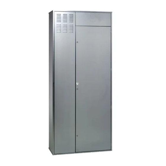
- Page 1 COD. 3.030394 CONTAINER Istruzioni e avvertenze SUPER TRIO SUPER TRIO Instructions and warnings IE CONTAINER...
-
Page 2: Avvertenze Generali
IL PRESENTE FOGLIO È DA LASCIARE ALL'UTENTE ABBINATO AL LIBRETTO ISTRUZIONI DEL PRODOTTO FINITO AVVERTENZE GENERALI. L’installazione o il montaggio improprio dell’ a pparecchio e/o dei Tutti i prodotti Immergas sono protetti con idoneo imballaggio componenti, accessori, kit e dispositivi Immergas potrebbe dare da trasporto. -
Page 3: Dimensioni Principali
Il telaio nella sua parte inferiore è dotato dei fori necessari per aspirazione (solo per installazione “tipo C”) mediante l’utilizzo gli allacciamenti idraulici, gas, elettrici, scarico condensa e per di fumisteria marcata Immergas (da utilizzare solo in presenza il collegamento della termoregolazione. di caldaia). - Page 4 DISTANZA MINIMA DI INSTALLAZIONE. ATTENZIONE Posizionare il lato sinistro del Container ad almeno 100 mm di distanza dalla parete per permettere le normali operazioni di manutenzione. Fig. 2...
- Page 5 DIMA ALLACCIAMENTO. Fig. 3 ALLACCIAMENTO POSTERIORE ALLACCIAMENTO LATERALE DESTRO Legenda: G - Alimentazione gas AC - Uscita acqua calda sanitario ALLACCIAMENTO INFERIORE AF - Entrata acqua sanitario LP - Linea frigorifera - stato liquido GP - Linea frigorifera - stato gassoso MZ - Mandata impianto MZ - Mandata impianto TABELLA ALLACCIAMENTI ZONE.
-
Page 6: Installazione
INSTALLAZIONE: N.B.: Il gruppo di allacciamento non è a corredo, ma venduto Predisporre le opere murarie creando un'apertura nella parete separatamente (optional). Per facilitare l’installazione è possibile dove verrà installato il telaio (1), facendo attenzione a preve- scegliere se operare l’allacciamento nella parte posteriore, nella dere lo spazio per i sei spacchi per inserire le rispettive alette parte inferiore o laterale (in basso a destra) del Container Super di sostegno (2) e uno spazio sotto il telaio sufficiente per poter... - Page 7 Legenda disegni installazione: Identificazione univoca componente Identificazione sequenziale operazione da svolgere Identificazione componente generico o non fornito in dotazione Fig. 4...
- Page 8 Fig. 5 Fig. 6 Fig. 7 Fig. 8...
-
Page 9: General Warnings
This instruction manual provides technical information for Installation and maintenance must be performed in compliance installing the Immergas kit. As for the other issues related to kit with the regulations in force, according to the manufacturer's in- installation (e.g. safety at the workplace, environmental protection,... -
Page 10: Main Dimensions
“C type” installations) and to the intake duct (only for “C The lower part of the frame is equipped with the holes necessary type” installation) using the Immergas flue. for the hydraulic, gas, electrical connections, condensate drain ATTENTION: it is not possible to exit on the left side with and for the connection of the thermoregulation. -
Page 11: Minimum Installation Distance
MINIMUM INSTALLATION DISTANCE. ATTENTION Place the left side of the Container at least 100 mm away from the wall to allow normal maintenance operations. Fig. 2... - Page 12 CONNECTION TEMPLATE. Fig. 3 REAR CONNECTION RIGHT HAND SIDE CONNECTION Key: G - Gas supply AC - Domestic hot water outlet LOWER CONNECTION AF - DHW (Domestic hot water) water inlet LP - Chiller line - liquid phase GP - Chiller line - gaseous phase MZ - System flow ZONE CONNECTION TABLE.
-
Page 13: Installation
INSTALLATION: N.B.: The connection unit is not supplied, but is sold separately Set-up the masonry jobs creating an opening in the wall where (optional). To ease installation, choose whether to make the the frame will be installed (1), paying attention to envision the connection at the rear, bottom or side (bottom right) of the space for the six slots for inserting the respective support fins Container Super Trio (see Fig. - Page 14 Drawings key installation: Unambiguous component identification Sequential identification of the operation to perform Identification of generic or not supplied componenent Fig. 4...
- Page 15 Fig. 5 Fig. 6 Fig. 7 Fig. 8...
- Page 16 Per richiedere ulteriori approfondimenti specifici, i Professionisti del settore possono anche avvalersi dell’indirizzo e-mail: consulenza@immergas.com To request further specific details, sector Professionals can also use the following e-mail address: consulenza@immergas.com Immergas S.p.A. 42041 Brescello (RE) - Italy Tel. 0522.689011 Fax 0522.680617...