SolarEdge SE K Series Installation Manual
Three phase inverters with synergy technology
Hide thumbs
Also See for SE K Series:
- Quick installation manual (288 pages) ,
- Installation manual (105 pages) ,
- Quick installation manual (25 pages)

Related Manuals for SolarEdge SE K Series


Summary of Contents for SolarEdge SE K Series
- Page 1 Installation Guide Three Phase Inverters with Synergy Technology Model Name: SExxxK for Australia Version 1.2...
-
Page 2: Disclaimers
No part of this document may be reproduced, stored in a retrieval system or transmitted, in any form or by any means, electronic, mechanical, photographic, magnetic or otherwise, without the prior written permission of SolarEdge Inc. All company and brand products and service names are trademarks or registered trademarks of their respective holders. -
Page 3: Emission Compliance
Emission Compliance Emission Compliance This equipment has been tested and found to comply with the limits applied by the local regulations. These limits are designed to provide reasonable protection against harmful interference. This equipment generates, uses and can radiate radio frequency energy and, if not installed and used in accordance with the instructions, may cause harmful interference to radio communications. - Page 4 Disclaimers 3 CAUTION! Where EN55011 Class A is deemed applicable, the following requirements apply: This equipment is not intended for use in residential environments and may not provide adequate protection to radio reception in such environments. This equipment should be connected to inverters with a rated power > 20 kVA and is intended to be installed in a large photovoltaic power generating system by a professional.
-
Page 5: Table Of Contents
Disclaimers Important Notice Emission Compliance Safety Warnings HANDLING AND SAFETY INSTRUCTIONS Safety Symbols Information Chapter 1: Introducing the SolarEdge Power Harvesting System Power Optimiser Three Phase Inverter with Synergy Technology Monitoring Platform Designer Installation Tools and Material List Installation Procedure... - Page 6 Disclaimers 5 Pre-commissioning (Off-Grid) Reporting and Monitoring Installation Data Chapter 6: Setting Up Communication with the Monitoring Platform Communication Options Communication Connectors Creating an Local Area Network (LAN) Connection Creating an RS485 Bus Connection RS485 Bus Configuration Verifying the Connection Signaling Options Appendix A: Errors and Troubleshooting Identifying Errors...
-
Page 7: Handling And Safety Instructions
SolarEdge Power Optimizers and/or inverters. Third party equipment is not compatible with SolarEdge equipment. WARNING! Using this equipment in a manner not specified by SolarEdge in this document may impair the protection provided by this equipment. WARNING! The inverter cover must be opened only after switching the inverter ON/OFF/P switch located at the bottom of the inverter to OFF. - Page 8 HEAVY OBJECT. To avoid muscle strain or back injury, use proper lifting techniques, and if required - a lifting aid. NOTE The symbol appears at grounding points on the SolarEdge equipment. This symbol is also used in this manual. Three Phase Inverters with Synergy Technology...
- Page 9 Safety Symbols Information NOTE SolarEdge inverters can be installed in sites with an alternative power source such as a generator. SolarEdge requires installing a physical or electronic interlock, which will signal to the inverter when the grid has been disconnected. Interlock procurement, installation, maintenance and support are the responsibility of the installer.
-
Page 10: Chapter 1: Introducing The Solaredge Power Harvesting System
Chapter 1: Introducing the SolarEdge Power Harvesting System The SolarEdge power harvesting solution is designed to maximize the power output from any type of solar Photovoltaic (PV) installation while reducing the average cost per Watt. Figure 1 shows and the following sections describe the components of the SolarEdge power harvesting system. -
Page 11: Three Phase Inverter With Synergy Technology
AC service of the site and from there to the grid. The inverter also receives the monitoring data from each Power Optimiser and transmits it to the SolarEdge Monitoring platform (requires a land-line or cellular connection to the Internet). -
Page 12: Monitoring Platform
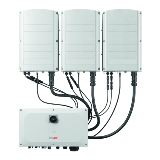
Figure 2: Synergy Manager with three Synergy Units Monitoring Platform The monitoring platform enables monitoring the technical and financial performance of one or more SolarEdge sites. It provides past and online information on the system performance, both at the system and PV module levels. Designer Designer recommends inverter and Power Optimiser selection per site size and enables report generation. -
Page 13: Installation Procedure
Four- or six-wire shielded twisted pair cable Watchmaker precision screwdriver set Installation Procedure The following procedures, are required for installing and setting up a new SolarEdge site. Some of these procedures also apply to modification of an existing site. 1. -
Page 14: Chapter 2: Installing The Power Optimisers
IMPORTANT SAFETY FEATURE Modules with SolarEdge Power Optimisers are safe. They carry only a low safety voltage before the inverter is turned ON. As long as the Power Optimisers are not connected to the inverter or the inverter is turned OFF, each Power Optimiser will output a safe voltage of 1V. -
Page 15: Installation Guidelines
For the minimum and maximum number of Power Optimisers in a PV string (PV string length), see the Power Optimiser datasheets. Refer to the Designer for PV string length verification. The Designer is available on the SolarEdge website at: . Do not use extension cables between a module and a Power Optimiser, between... - Page 16 Frame-mounted Power Optimisers are mounted directly on the module frame, regardless of racking system (rail-less or with rails). For installation of frame- mounted Power Optimisers, refer to http://www.solaredge.com/sites/default/files/installing_frame_mounted_power_ optimizers.pdf. The Power Optimiser can be placed in any orientation. If connecting more modules than Power Optimiser inputs in parallel, use a branch cable.
- Page 17 Installation Guidelines P860, P960 and M1600 Power Optimisers Figure 3: Power Optimisers clearance When installing PV modules in a confined space such as Building-integrated photovoltaic (BIPV) modules, ventilation measures may be required to ensure that the Power Optimisers are not exceeding the maximum temperatures stated in their specifications.
-
Page 18: Step 1: Mounting The Power Optimisers
. It is recommended to mount the Power Optimiser in a location protected from direct sunlight. For frame-mounted Power Optimisers follow the instructions supplied with the optimisers, or refer to https://www.solaredge.com/sites/default/files/installing_frame_ mounted_power_optimizers.pdf. 2. If required, mark the mounting hole locations and drill holes. CAUTION! Drilling vibrations may damage the Power Optimiser and will void the warranty. -
Page 19: Step 3: Connecting Power Optimisers In Pv Strings
You can construct parallel PV strings of unequal length, that is, the number of Power Optimisers in each PV string does not have to be the same. The minimum and maximum PV string lengths are specified in the power datasheets. Refer to the SolarEdge Site Designer for PV string length verification. -
Page 20: Step 4: Verifying Proper Power Optimiser Connection
19 Figure 5: Power Optimisers connected in series 4. If you intend to monitor the installation, using the SolarEdge Monitoring platform, record the physical location of each Power Optimiser, as described in Creating Logical and Physical Layout using Installation Information on page 49. - Page 21 Step 4: Verifying Proper Power Optimiser Connection For troubleshooting Power Optimiser operation problems, refer to Power Optimiser Troubleshooting on page 66. Proper Power Optimiser connection can also be verified in the Designer application. For more information, refer to https://www.solaredge.com/products/installer-tools/designer#/. Three Phase Inverters with Synergy Technology...
-
Page 22: Chapter 3: Installing The Synergy Manager And Synergy Units
Two Allen screws for fastening the unit to the mounting bracket Identifying the Units Stickers on the Synergy Manager and Synergy Units show Serial Numbers. When creating a site in the SolarEdge Monitoring platform or contacting SolarEdge support, provide the inverter's serial number. Three Phase Inverters with Synergy Technology... -
Page 23: Front Interface Of Synergy Manager
Some models Synergy Manager do not include DC Disconnect Switch. DC Disconnect Switch The DC Disconnect Switch is a manually operated safety switch for disconnecting the DC power of the SolarEdge system. NOTE When the Synergy Manager is OFF (for example during maintenance) it may be locked to prevent a safety hazard: 1. - Page 24 5 seconds, then is in P, all LEDs exist) for 5 seconds. released. are ON Activates the Wi-Fi access point for connecting to the SolarEdge Inverter SetApp Switch moved to P for more than 5 seconds, Starts pairing ...
- Page 25 Front Interface of Synergy Manager Indication LEDs LEDs indication consists on color and state (on/ off/ blinking / flickering /alternating ). The LEDs indicate different system information, such as errors or performance. Figure 8 shows the Indication LEDs of the Synergy Manager. Generally, the main LED indications are: COMM.
- Page 26 Chapter 3: Installing the Synergy Manager and Synergy Units 25 ON/ OFF/ LED Indication Comment switch FAULT POWER COMM. position S_OK: ON communication S_OK: ON Power with the Optimisers not Blinking No S_OK: monitoring paired platform is established Pairing Blinking Blinking Blinking ...
-
Page 27: Inverter Interconnection Cable Interfaces
Inverter Interconnection Cable Interfaces The following table describes production percentage of AC information by LED color and ON/OFF/P switch position. ON/ OFF/ LED color Indication Comment switch Green Blue position Percentage of AC This indicates Production: 0 - 33 % power production Percentage of AC ON (1) as percentage of... -
Page 28: Synergy Manager External Cable Interface
The conduit entries, at the bottom side of the Synergy Manager, interfaces the inverter to the grid and PV arrays. The communication glands, support communication cables connecting the inverter to the SolarEdge Monitoring platform and external power bank used for setting up the inverter in sites with no available grid power. - Page 29 Synergy Unit Interface Connectors AC connector: for supply of AC power to the Synergy Manager Figure 11: Synergy Unit Interface Connectors Figure 12: Synergy Unit AC and Communication Connectors Figure 13: Synergy Unit DC Connector Three Phase Inverters with Synergy Technology...
-
Page 30: Drilling Conduit Holes
Chapter 3: Installing the Synergy Manager and Synergy Units 29 Drilling Conduit Holes This section describes how to drill AC and DC openings at the bottom of the Synergy Manager for connecting the AC and DC conduits. This procedure must be performed before mounting the Synergy Manager. To open conduit drill guides: 1. -
Page 31: Mounting And Connecting The Synergy Manager And Synergy Units
Mounting and Connecting the Synergy Manager and Synergy Units Figure 14: AC and DC panels with drill guides at the bottom of the Synergy Manager 3. Locate the drill guides for conduits on the DC and AC panels. Drill entry hole(s) for up to 5 cm conduit on the DC panel and6.35 cm on the AC panel or drill entry hole for a single conduit, within the boundary marked on the inner side of the DC panel (see Figure 14 ). - Page 32 Power Optimiser. For SolarEdge inverters installed at a distance of 200 m or closer to the shoreline, special brackets purchased separately from SolarEdge and SS304 stainless screws are required.
- Page 33 Mounting and Connecting the Synergy Manager and Synergy Units Figure 15: Marking the drilling holes locations 4. Place the mounting templates vertically against the wall and mark the drilling hole locations for the bracket of the Synergy Manager. Make sure that the template aligns with the two drilling holes marked A.
- Page 34 Chapter 3: Installing the Synergy Manager and Synergy Units 33 Lift the Synergy Unit from the sides, or hold it at the top and bottom of the unit to lift into place. Align the two indentations in the enclosure with the two triangular mounting tabs of the bracket, and lower the unit until it rests on the bracket evenly (see Figure 17 ).
- Page 35 Mounting and Connecting the Synergy Manager and Synergy Units Figure 17: Hanging the Synergy Manager Horizontal Mounting of the Inverter The inverter can be installed horizontally, on a flat surface, at any tilt above 10° (see Figure 18 ). The inverter can be installed under or near the PV modules, thus saving roof space and using the PV modules for shading the inverter.
-
Page 36: Chapter 4: Connecting Ac And Pv Arrays To The Synergy Manager
Figure 19: Synergy Manager - DC connection to PV arrays NOTE SolarEdge fixed input Voltage architecture enables parallel PV strings to be of different lengths. Therefore, they do not need to have the same number of Power Optimisers as long as the length of each PV string is within the permitted range. - Page 37 When installing a system with more than 3 PV strings per a single Synergy Unit (whether connected directly or via a combiner box), fuses are required. In SolarEdge system, 25A fuses must be used (). Figure 20: Connecting the DC wires to the Synergy Manager 3.
-
Page 38: Connecting Ground And Ac Wires To The Synergy Manager
When installing a system with more than three PV arrays per a single Synergy Unit (whether connected directly or via a combiner box), fuses are required. In SolarEdge system, 25A fuses must be used. Connecting Ground and AC Wires to the Synergy... - Page 39 Connecting Ground and AC Wires to the Synergy Manager Use AC line wires with a maximum of 120 mm cross section conductor (For inverter models SE50K and SE66.6K use 95 mm Use PE wire with a maximum of 70 mm cross section conductor (For inverter models SE50K and SE66.6K use 95 mm CAUTION!
- Page 40 CAUTION! When removing the cover, make sure not to damage internal components. SolarEdge will not be held responsible for any components damaged as a result of incautious cover removal. 3. Strip 10 to 11 mm of insulation from the PE wire.
- Page 41 Connecting Ground and AC Wires to the Synergy Manager NOTE Ground the conduit nut if required by regulation. To connect AC wires to the Synergy Manager: 1. Verify that the main AC circuit breaker is in OFF position at the circuit breakers panel. 2.
- Page 42 Chapter 4: Connecting AC and PV arrays to the Synergy Manager 41 Figure 24: Crimping a lug on an AC wire Lug parameters: Bolt hole diameter size: 10mm Compression lugs of the one-hole, standard barrel, 600V type. Maximum wire size: 120mm (For inverter models SE50K, SE55K, SE66.6K, SE80K use 95>mm Maximum lug tongue thickness: 7mm...
- Page 43 Connecting Ground and AC Wires to the Synergy Manager Figure 25: Connecting AC wires to the AC terminals 8. Place the upper cover of the AC terminal block and push until a lock click is heard. Close the Synergy Manager cover and secure it by tightening the six screws with a torque of 3.5 N*m.
-
Page 44: Chapter 5: Activating, Commissioning And Configuring The System
For communication options, refer to: Setting Up Communication with the Monitoring Platform on page 50. Before arriving at the site, download SolarEdge SetApp application to your mobile device from Apple App Store or Google Play . -
Page 45: On-Grid Commissioning Of The Inverter
On-grid Commissioning of the inverter On-grid Commissioning of the inverter Step 1: Activating the Installation During system activation, a Wi-Fi connection is created between the mobile device and the inverter and the system firmware is upgraded. Before activation Download, register (first time only) and login to SetApp on your mobile device. Verify that the application is updated with the latest version. - Page 46 Chapter 5: Activating, Commissioning and Configuring the System 45 If the inverter has already been activated and commissioned: If not already ON - turn ON AC to the inverter by turning ON the circuit breaker on the main distribution panel. Open SetApp and follow the on-screen instructions (scan the inverter QR code, move the ON/OFF/P switch to P position for 2 seconds and release).
-
Page 47: Step 3: Verifying Proper Activation And Commissioning
Select Monitoring Communication to configure communication with the monitoring platform. Select Site Communication to configure communication between multiple SolarEdge devices or external non-SolarEdge devices, such as batteries or loggers. Power Control Power control options are detailed in the Power Control Application Note , available on the SolarEdge website at: https://www.solaredge.com/sites/default/files/application_... - Page 48 1. Turn OFF and secure the AC circuit breaker in OFF position in the circuit breakers panel. 2. Verify that SolarEdge SetApp is installed on your mobile device. 3. Turn the DC Disconnect Switch on the Synergy Manager to ON position (if applicable).
-
Page 49: Reporting And Monitoring Installation Data
Reporting and Monitoring Installation Data Monitoring the site requires connecting the inverter to the monitoring platform, using any of the wired or wireless options available from SolarEdge. Refer to Setting Up Communication with the Monitoring Platform on page 50. The Monitoring Platform... - Page 50 49 The monitoring platform includes a built-in help system that guides you through the monitoring functionality. For more information, refer to https://www.solaredge.com/products/pv- monitoring#/. Creating Logical and Physical Layout using Installation Information To display a logical layout, insert in the new site created in the monitoring platform.
-
Page 51: Chapter 6: Setting Up Communication With The Monitoring Platform
NOTE This guide refers to 3rd party communication products, such as internet switches and routers that are not supported by SolarEdge. For detailed information on how to install and use the products, refer to the respective publication provided with each product. -
Page 52: Communication Connectors
Chapter 6: Setting Up Communication with the Monitoring Platform 51 RS485 RS485 is used for the connection of multiple SolarEdge devices on the same bus in a leader-follower configuration. RS485 can also be used as an interface to external devices, such as meters and third party data loggers. - Page 53 Communication Connectors Figure 27: Synergy Manager - Communication Glands Table52 describes the openings of the communication glands of the Synergy Manager. Table 1: Synergy Manager - Communication Glans Gland# Opening Functionality Three large openings Ethernet cable (CAT6), Power reduction 2.5-5 mm cable Synergy...
- Page 54 Chapter 6: Setting Up Communication with the Monitoring Platform 53 Communication Board The communication board is located, inside the Synergy Manager and serves as the communication hub of the inverter. Figure 28: Synergy Manager - communication board The Communication Board includes the following interface connectors: Cellular antenna - Antenna port for a Cellular Plug-in modem connecting the inverter to the internet.
-
Page 55: Creating An Local Area Network (Lan) Connection
4. Release the six Allen screws of the cover and remove the Synergy Manager cover. CAUTION! When removing the cover, make sure not to damage internal components. SolarEdge will not be held responsible for any components damaged as a result of incautious cover removal. Creating an Local Area Network (LAN) Connection This communication option enables connection to the SolarEdge monitoring platform via Ethernet. - Page 56 Chapter 6: Setting Up Communication with the Monitoring Platform 55 To connect the Ethernet cable: 1. Remove of the cover of the communication board compartment. 2. Remove the nut of the COMM1 gland. CAUTION! The gland includes a rubber waterproof fitting, which should be used to ensure proper sealing.
- Page 57 Creating an Local Area Network (LAN) Connection Figure 30: Inserting the Ethernet (CAT6) cable 8. Route the Ethernet cable to the communication board and plug to the LAN port. 9. Crimp an RJ45 plug on the Ethernet cable. 10. Tighten the gland nut with a torque of . 11.
- Page 58 ELECTRICAL SHOCK HAZARD. Do not touch uninsulated wires when the Synergy Manager cover is removed. d. Use the SolarEdge SetApp to access the Commissioning main menu screen as described in "Activating, Commissioning and Configuring the System" on page 43"Activating, Commissioning and Configuring the System" on page 43 .
- Page 59 LAN by default. NOTE If your network has a firewall, you may need to configure it to enable the connection to the following address: Destination Address: prodssl.solaredge.com Modbus TCP Port: 443 (for incoming and outgoing data) Three Phase Inverters with Synergy Technology...
-
Page 60: Creating An Rs485 Bus Connection
Chapter 6: Setting Up Communication with the Monitoring Platform 59 Creating an RS485 Bus Connection The RS485 option enables creating a bus of connected inverters, consisting of up to 31 follower inverters and 1 leader inverter. Using this option, inverters are connected to each other in a bus (chain), via their RS485 connectors. - Page 61 Creating an RS485 Bus Connection Figure 32: RS485 terminal block on the communication board 4. Loosen the screws of pins A(+), B(-), and G on the left of the RS485 terminal block (RS485-1 or RS485-2). Figure 33: RS485 terminal block 5.
- Page 62 9. Push the RS485 terminal block firmly all the way into the connector on the right side of the communication board. 10. Terminate the first and last SolarEdge device in the chain by switching a termination DIP-switch inside the inverter to ON (move the left switch up). The DIP-switch is located on the communication board and is marked SW1.
-
Page 63: Rs485 Bus Configuration
RS485 Bus Configuration Figure 35: RS485 termination DIP-switch (SW1) NOTE Only the first and last SolarEdge devices in the chain should be terminated. The other inverters in the chain should have the termination switch OFF (down position). 11. Tighten the nut of the COMM2 gland in a torque of 4 N*m. -
Page 64: Verifying The Connection
Chapter 6: Setting Up Communication with the Monitoring Platform 63 Verifying the Connection After connecting and configuring a communication option, perform the following steps to check that the connection to the Monitoring platform has been successfully established. 1. If the Synergy Manager cover is not closed, close it: Attach the cover and secure it by tightening the screws with a torque of . - Page 65 Figure 37 ) is used signaling the inverter to switch to Alternative Power Source mode. Figure 37: PRI Terminal Block Location on the Communication Board of the Inverter For detailed connection and configuration of the inverter in alternative power source mode, refer to: https://www.solaredge.com/sites/default/files/se-inverter-support-of- voltage-sources.pdf Three Phase Inverters with Synergy Technology...
-
Page 66: Appendix A: Errors And Troubleshooting
65 Appendix A: Errors and Troubleshooting This chapter describes how to troubleshoot general system problems. For further assistance, contact SolarEdge Support. Identifying Errors Errors may be indicated in various system interfaces: On the inverter bottom panel, a red LED indicates an error. In the monitoring platform and SetApp, errors are displayed with codes. -
Page 67: Power Optimiser Troubleshooting
Power Optimiser Troubleshooting Power Optimiser Troubleshooting Malfunction Possible Cause and Corrective Action Power Optimisers are shaded. If you connected the inverter to the monitoring platform, retry pairing remotely (during Pairing failed sunlight). Make sure to leave the inverter ON/OFF/P switch ON and that S_OK appears in the status screen. - Page 68 1V safety Voltage. If a malfunctioning Power Optimisers located, check its connections, polarity, module, and Voltage. 3. Contact SolarEdge Support. Do not continue before finding the problem and replacing the malfunctioning Power Optimiser. If a malfunction cannot be bypassed or resolved, skip the malfunctioning Power Optimiser, thus connecting a shorter PV string.
-
Page 69: Troubleshooting Communication
If after follower detection the number of followers displayed for the leader under RS485-1 > Follower Detect is lower than the actual number of followers, refer to the following application note to identify missing followers and troubleshoot connectivity problems: https://www.solaredge.com/sites/default/files/troubleshooting_undetected_RS485_ devices.pdf Three Phase Inverters with Synergy Technology... - Page 70 3. Check that the selected communication option is properly configured. 4. Use a method independent of the SolarEdge device to check whether the network and modem are operating properly. For example, connect a laptop to the Ethernet router and connect to the Internet.
-
Page 71: Appendix B: Adding Optional Components
AC grid lines. The SPD limits the Voltage supplied to the inverter by either blocking or shorting to ground Voltages above a safe threshold. The SPD is installed inside the inverter and communicates with the SolarEdge Monitoring platform for reporting surge protection events and faults. -
Page 72: Cellular Plug-In
71 Cellular Plug-in The cellular plug-in provides wireless communication between the inverter and the SolarEdge monitoring platform. The Cellular Plug-in kit is provided with an antenna and user manual. For more information on the Cellular Plug-in, refer to: https://www.solaredge.com/sites/default/files/cellular_gsm_installation_guide_for_ inverters_with_setapp.pdf... -
Page 73: Appendix C: Mechanical Specifications
Appendix C: Mechanical Specifications Appendix C: Mechanical Specifications The following figure shows the dimensions of the Three Phase Inverter with Synergy Technology. Three Phase Inverters with Synergy Technology... - Page 74 ...