
Related Manuals for Vaisala HMT370EX


Summary of Contents for Vaisala HMT370EX
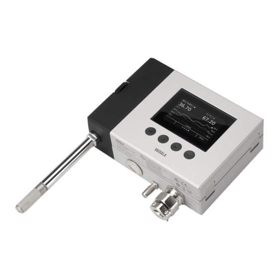
- Page 1 M212305EN-B User Guide Intrinsically Safe Humidity and Temperature Transmitter Series HMT370EX...
- Page 2 English versions are This product contains software developed applicable, not the translations. by Vaisala or third parties. Use of the The contents of this document are subject software is governed by license terms and to change without prior notice.
-
Page 3: Table Of Contents
Using HMT370EX Series transmitters in hazardous locations...26 3.3.2 Guidelines for safe use in hazardous conditions......... 28 China safety certification information............32 3.4.1 Using HMT370EX Series transmitters in hazardous locations... 32 3.4.2 Guidelines for safe use in hazardous conditions.........34 Korea safety certification information............38 3.5.1 Using HMT370EX Series transmitters in hazardous locations...38... - Page 4 79 Installation......................81 HMT370EX installation overview..............81 5.1.1 Installation preparations.................82 5.1.2 Probe installation overview..............83 5.1.3 HMT370EX transmitter dimensions............83 Mounting......................84 Attaching cable glands and conduit fittings..........85 Wiring......................86 5.4.1 Wiring with galvanic isolators............... 88 5.4.2 Wiring with Zener barriers..............89 Finalizing installation: closing transmitter and attaching grounding..90...
- Page 5 Calibration and adjustment..............119 10.1 Calibration and adjustment overview............119 10.2 Adjusting measurements with Insight............120 10.3 Adjusting measurements with HMT370EX local display interface..120 10.4 Analog output adjustment overview............122 10.4.1 Adjusting analog output level with Insight.........124 10.4.2 Adjusting analog output level with local display interface....125 Maintenance....................
- Page 6 HMT370EX User Guide M212305EN-B Technical support...................147 Recycling......................147...
- Page 7 Duct installation example with HMP373 probe and duct installation kit....................83 Figure 34 HMT370EX transmitter dimensions............83 Figure 35 Mounting HMT370EX directly through the transmitter body.... 84 Figure 36 Wiring example using one cable..............87 Figure 37 Wiring diagram with galvanic isolators............88 Figure 38 Wiring diagram with Zener barriers............
- Page 8 Display PIN code button presses............... 96 Figure 46 Dark (left) and light (right) display theme examples......97 Figure 47 Transmitter display in sleep mode............. 97 Figure 48 HMT370EX display interface main menu..........98 Figure 49 Settings menu....................98 Figure 50 Display menu....................99 Figure 51 Analog output settings................
- Page 9 Available measurement parameters for HMP378F and HMP378H..12 Table 5 LED status indicator states................15 Table 6 Cable lead-through accessories..............18 Table 7 HMT370EX Series regional Ex classifications..........19 Table 8 HMT370EX series hazardous area classifications........21 Table 9 Allowed ambient temperature ranges............23 Table 10 Intrinsically safe input parameters...............24...
- Page 10 HMT370EX User Guide M212305EN-B Table 45 HMP371 for wall mounting................136 Table 46 HMP373 for confined spaces................ 137 Table 47 HMP374 for high pressure................138 Table 48 HMP375 for high temperature..............138 Table 49 HMP377 for high humidities................. 139 Table 50 HMP378 for pressurized pipelines..............140...
-
Page 11: About This Document
First version of the document. 1.2 Related manuals Table 2 Related manuals Document code Description M212306EN HMT370EX Multilingual Installation and Safety Guide (languages: English, German, French, Dutch, Spanish, Portuguese, Italian, Hungarian, Czech, Polish, Finnish, Estonian, Swedish, Norwegian, Danish) M212662EN HMT370EX Multilingual Installation and Safety Guide (languages:... -
Page 12: Documentation Conventions
HMT370EX Multilingual Installation and Safety Guide (languages: English and Chinese) M212717EN HMT370EX Multilingual Installation and Safety Guide (languages: English and Korean) M212733EN HMT370EX Installation and Safety Guide (language: English, for US FM certification). M212707EN HMT370EX Installation and Safety Guide (language: English, for US/CAN MET certification). M212752EN HMT370EX Installation and Safety Guide (language: English, for UK/ UKEX certification). -
Page 13: Product Overview
Intrinsically safe and robust, HMT370EX operates safely and reliably even in the most hazardous areas, such as Zone 0. HMT370EX transmitters can be used as a replacement for the long-running HMT360 transmitter series in all HMT360 applications. -
Page 14: Available Measurement Parameters
M212305EN-B 2.4 Available measurement parameters Table 3 (page 12) lists the available HMT370EX measurement parameter options and their abbreviations and units for the standard probe options HMP371, HMP373, HMP374, HMP375, HMP377, and HMP378. Table 3 Available measurement parameters for HMP371, HMP373, HMP374, HMP375, HMP377, and... - Page 15 Chapter 2 – Product overview Parameter Abbreviation Unit Only available for HMP378F O (oil) Water concentration in oil Only available for HMP378H Water concentration in JET A-1 O (fuel) fuel Saturation temperature °C (°F) The default calculation coefficients for water concentration in oil (ppm ) are valid for mineral transformer oil.
-
Page 16: Display Options
HMT370EX User Guide M212305EN-B 2.5 Display options The HMT370EX transmitter can be ordered either with a graphical LCD display, or alternatively without a display. The display options are shown in Figure 1 (page 14). Figure 1 HMT370EX transmitter display options Transmitter with display: LCD display with 4-button interface... -
Page 17: Connectivity To Vaisala Insight Software
Critical error. Connect to Insight to view status information and configure. 2.6 Connectivity to Vaisala Insight software The HMT370EX transmitter and HMT370EX series probes can be connected to Vaisala Insight software either together as one unit or separately with a Vaisala USB cable (see Spare parts and accessories (page 141)). -
Page 18: Transmitter Parts
Figure 2 (page 16), and the internal parts of the transmitter are shown in Figure 3 (page 17). Figure 2 HMT370EX transmitter external parts Detachable probe body Transmitter body (for internal parts, see Figure 3 (page 17)) Graphical LCD display (see... -
Page 19: Cable Gland And Conduit Options
Transmitter service port (M8, requires Vaisala USB cable accessory) 2.7.1 Cable gland and conduit options The HMT370EX transmitter body has two M20x1.5 lead-throughs that can be fitted with cable glands, conduit fittings, and plugs, as required by your application. By default, the transmitter... -
Page 20: Figure 4 Default Plugs In Hmt370Ex Lead-Throughs
HTM370EX. The metal sealing plug (2) can be left in place and used in the final installation, if the right-hand lead-through is not used. Cable glands, conduits, and plugs are available from Vaisala as accessories (listed in Table 6 (page 18)). -
Page 21: Hmt370Ex Regional Safety Certification Information
HMT370EX Series Ex classification by region Table 7 (page 19) shows the Ex classification of HMT370EX in each certification region. For the most up-to-date list of regional certifications, see the HMT370EX product page www.vaisala.com/HMT370EX. Table 7 HMT370EX Series regional Ex classifications... -
Page 22: Atex/Iecex Safety Certification Information
ATEX (EU) and IECEx (international) certifications. The Vaisala document code of the multilingual (EN, DE, FR, NL, ES, PT, IT, HU, CS, PL, FI, ET, SV, NO, DA) ATEX and IECEx version of HMT370EX Installation and Safety Guide is M212306EN. -
Page 23: Table 8 Hmt370Ex Series Hazardous Area Classifications
Chapter 3 – HMT370EX regional safety certification information HMT370EX does not include a galvanic isolator or a Zener barrier. They can be ordered as optional accessories from Vaisala. WARNING! HMT370EX series transmitters have been designed for use in hazardous locations as specified by the product classification. The personnel... -
Page 24: Guidelines For Safe Use In Hazardous Conditions
M20x1.5 M20x1.5 Figure 5 HMT370EX parts overview HMT370EX Series transmitters consist of 3 main parts: the transmitter body, a detachable probe body, and a probe head attached to the probe body, either directly or using a cable. Figure 5 (page 22) shows the main parts. -
Page 25: Table 9 Allowed Ambient Temperature Ranges
Chapter 3 – HMT370EX regional safety certification information Table 9 Allowed ambient temperature ranges Equipment part Allowed ambient temperature range Transmitter body -40 °C … +60 °C (-40 … +140 °F) Probe body -40 °C … +60 °C (-40 … +140 °F) -
Page 26: Table 10 Intrinsically Safe Input Parameters
Intrinsic safety The overvoltage category of HMT370EX transmitters is I (non-mains equipment), and ambient pollution degree is 4, as specified in IEC 60664-1. For intrinsically safe input parameters, see Table 10 (page 24) Table 10 ... -
Page 27: Figure 6 Location Of Test Points And Service Port
25)) must only be used in a safe area. Either remove the transmitter from the hazardous area or ensure that a safe work procedure has been implemented in the hazardous area. Only use the Vaisala accessory PC connection cable with the service port. -
Page 28: Japan Safety Certification Information
For wiring information, see the galvanic isolator and Zener barrier wiring diagrams included in this document. HMT370EX does not include a galvanic isolator or a Zener barrier. They can be ordered as optional accessories from Vaisala. WARNING! HMT370EX Series transmitters have been designed for use in hazardous locations as specified by the product classification. -
Page 29: Table 11 Hmt370Ex Series Hazardous Area Classifications
For information on the standards that apply to using HMT370EX based on the classification of the device, see HMT370EX certification documentation and the declarations of conformity... -
Page 30: Guidelines For Safe Use In Hazardous Conditions
M20x1.5 M20x1.5 Figure 7 HMT370EX parts overview HMT370EX Series transmitters consist of 3 main parts: the transmitter body, a detachable probe body, and a probe head attached to the probe body, either directly or using a cable. Figure 7 (page 28) shows the main parts. -
Page 31: Table 12 Allowed Ambient Temperature Ranges
Chapter 3 – HMT370EX regional safety certification information Table 12 Allowed ambient temperature ranges Equipment part Allowed ambient temperature range Transmitter body -40 °C … +60 °C (-40 … +140 °F) Probe body -40 °C … +60 °C (-40 … +140 °F) -
Page 32: Table 13 Intrinsically Safe Input Parameters
Intrinsic safety The overvoltage category of HMT370EX transmitters is I (non-mains equipment), and ambient pollution degree is 4, as specified in IEC 60664-1. For intrinsically safe input parameters, see Table 13 (page 30). -
Page 33: Figure 8 Location Of Test Points And Service Port
31)) must only be used in a safe area. Either remove the transmitter from the hazardous area or ensure that a safe work procedure has been implemented in the hazardous area. Only use the Vaisala accessory PC connection cable with the service port. -
Page 34: China Safety Certification Information
For wiring information, see the galvanic isolator and Zener barrier wiring diagrams included in this document. HMT370EX does not include a galvanic isolator or a Zener barrier. They can be ordered as optional accessories from Vaisala. WARNING! HMT370EX series transmitters have been designed for use in hazardous locations as specified by the product classification. -
Page 35: Table 14 Hmt370Ex Series Hazardous Area Classifications
For information on the standards that apply to using HMT370EX based on the classification of the device, see HMT370EX certification documentation and the declarations of conformity... -
Page 36: Guidelines For Safe Use In Hazardous Conditions
M20x1.5 M20x1.5 Figure 9 HMT370EX parts overview HMT370EX Series transmitters consist of 3 main parts: the transmitter body, a detachable probe body, and a probe head attached to the probe body, either directly or using a cable. Figure 9 (page 34) shows the main parts. - Page 37 -70 °C … +180 °C (-94 … +356 °F) 3.4.2.1 Specific conditions of use The associated “X” suffix for the HMT370EX certificate number indicates the following specific conditions of use: • With the installation of the equipment in EPL Ga Group II, when the enclosure is made from aluminum alloy, it has to be ensured that sparks due to impact or friction do not occur.
-
Page 38: Table 16 Intrinsically Safe Input Parameters
Intrinsic safety The overvoltage category of HMT370EX transmitters is I (non-mains equipment), and ambient pollution degree is 4, as specified in IEC 60664-1. For intrinsically safe input parameters, see Table 16 (page 36). -
Page 39: Figure 10 Location Of Test Points And Service Port
Chapter 3 – HMT370EX regional safety certification information Parameter Value Associated apparatus entity parameters 100 mA ≤ I 700 mW ≤ P 12.1 nF ≥ C cable 16 µH ≥ L cable Using analog output test points There are test points for measuring the voltages and currents of the analog outputs, located... -
Page 40: Korea Safety Certification Information
For wiring information, see the galvanic isolator and Zener barrier wiring diagrams included in this document. HMT370EX does not include a galvanic isolator or a Zener barrier. They can be ordered as optional accessories from Vaisala. -
Page 41: Table 17 Hmt370Ex Series Hazardous Area Classifications
For information on the standards that apply to using HMT370EX based on the classification of the device, see HMT370EX certification documentation and the declarations of conformity... -
Page 42: Guidelines For Safe Use In Hazardous Conditions
M20x1.5 M20x1.5 Figure 11 HMT370EX parts overview HMT370EX Series transmitters consist of 3 main parts: the transmitter body, a detachable probe body, and a probe head attached to the probe body, either directly or using a cable. Figure 11 (page 40) shows the main parts. - Page 43 Chapter 3 – HMT370EX regional safety certification information Equipment part Allowed ambient temperature range Probe head HMP371 Temperature class T4: -40 °C … +60 °C (-40 … +140 °F) Probe head HMP373 Rubber cable version: Temperature class T6: -40 °C … +55 °C (-40 … +131 °F) Temperature class T5: -40 °C …...
-
Page 44: Figure 12 Location Of Test Points And Service Port
Intrinsic safety The overvoltage category of HMT370EX transmitters is I (non-mains equipment), and ambient pollution degree is 4, as specified in IEC 60664-1. For intrinsically safe input parameters, see Table 19 (page 42). -
Page 45: Fm) Safety Certification Information
3.6 US (FM) safety certification information This chapter contains the safety certification information (for example, specific conditions of use) related to the HMT370EX Series Ex certification in the US (Factory Mutual (FM) certification). The Vaisala document code of the US (FM) certification version of HMT370EX Installation and Safety Guide is M212733EN. -
Page 46: Table 20 Hmt370Ex Series Hazardous Area Classifications
For wiring information, see the galvanic isolator and Zener barrier wiring diagrams included in this document. HMT370EX does not include a galvanic isolator or a Zener barrier. They can be ordered as optional accessories from Vaisala. WARNING! HMT370EX series transmitters have been designed for use in hazardous locations as specified by the product classification. -
Page 47: Guidelines For Safe Use In Hazardous Conditions
For information on the standards that apply to using HMT370EX based on the classification of the device, see HMT370EX certification documentation and the declarations of conformity related to HMT370EX at www.vaisala.com/declarationofconformity. -
Page 48: Table 21 Allowed Ambient Temperature Ranges
HMT370EX User Guide M212305EN-B The different probe head variants are designed for a range of applications, and have their own specifications. Ensure that the transmitter body, probe body, and probe head are each placed in an environment that matches the specification of the part. For allowed ambient temperature... -
Page 49: Table 22 Intrinsically Safe Input Parameters
FM Approvals control drawing (page 49) before installation. Intrinsic safety The overvoltage category of HMT370EX transmitters is I (non-mains equipment), and ambient pollution degree is 4, as specified in IEC 60664-1. For intrinsically safe input parameters, see Table 22 (page 47). -
Page 50: Figure 14 Location Of Test Points And Service Port
48)) must only be used in a safe area. Either remove the transmitter from the hazardous area or ensure that a safe work procedure has been implemented in the hazardous area. Only use the Vaisala accessory PC connection cable with the service port. -
Page 51: Figure 15 Fm Approved Wiring Diagram For Intrinsically Safe Operation
Chapter 3 – HMT370EX regional safety certification information 3.6.2.2 FM Approvals control drawing Figure 15 (page 49) describes the FM Approvals requirements for intrinsic safety when wiring HMT370EX series transmitters. The content in this section is maintained in Vaisala document M212732EN. HAZARDOUS AREA SAFE AREA HMT370EX connection board Use FM approved associated apparatus;... -
Page 52: Can (Met) Safety Certification Information
For wiring information, see the galvanic isolator and Zener barrier wiring diagrams included in this document. HMT370EX does not include a galvanic isolator or a Zener barrier. They can be ordered as optional accessories from Vaisala. WARNING! HMT370EX series transmitters have been designed for use in hazardous locations as specified by the product classification. -
Page 53: Table 23 Hmt370Ex Series Hazardous Area Classifications
For information on the standards that apply to using HMT370EX based on the classification of the device, see HMT370EX certification documentation and the declarations of conformity... -
Page 54: Guidelines For Safe Use In Hazardous Conditions
M20x1.5 M20x1.5 Figure 16 HMT370EX parts overview HMT370EX Series transmitters consist of 3 main parts: the transmitter body, a detachable probe body, and a probe head attached to the probe body, either directly or using a cable. Figure 16 (page 52) shows the main parts. - Page 55 Chapter 3 – HMT370EX regional safety certification information Equipment part Allowed ambient temperature range Probe head HMP371 Temperature class T4: -40 °C … +60 °C (-40 … +140 °F) Probe head HMP373 Rubber cable version: Temperature class T6: -40 °C … +55 °C (-40 … +131 °F) Temperature class T5: -40 °C …...
-
Page 56: Figure 17 Location Of Test Points And Service Port
Intrinsic safety The overvoltage category of HMT370EX transmitters is I (non-mains equipment), and ambient pollution degree is 4, as specified in IEC 60664-1. For intrinsically safe input parameters, see Table 25 (page 54). -
Page 57: Ukex) Safety Certification Information
54)) must only be used in a safe area. Either remove the transmitter from the hazardous area or ensure that a safe work procedure has been implemented in the hazardous area. Only use the Vaisala accessory PC connection cable with the service port. -
Page 58: Table 26 Hmt370Ex Series Hazardous Area Classifications
For wiring information, see the galvanic isolator and Zener barrier wiring diagrams included in this document. HMT370EX does not include a galvanic isolator or a Zener barrier. They can be ordered as optional accessories from Vaisala. WARNING! HMT370EX series transmitters have been designed for use in hazardous locations as specified by the product classification. -
Page 59: Guidelines For Safe Use In Hazardous Conditions
Chapter 3 – HMT370EX regional safety certification information For information on the standards that apply to using HMT370EX based on the classification of the device, see HMT370EX certification documentation and the declarations of conformity related to HMT370EX at www.vaisala.com/declarationofconformity. 3.8.2 Guidelines for safe use in hazardous conditions... -
Page 60: Table 27 Allowed Ambient Temperature Ranges
HMT370EX User Guide M212305EN-B CAUTION! Removing or modifying parts is not permitted. Modifications carried out by the user can impair the Ex protection of the device or otherwise damage the device. Table 27 Allowed ambient temperature ranges Equipment part Allowed ambient temperature range Transmitter body -40 °C …... -
Page 61: Table 28 Intrinsically Safe Input Parameters
Intrinsic safety The overvoltage category of HMT370EX transmitters is I (non-mains equipment), and ambient pollution degree is 4, as specified in IEC 60664-1. For intrinsically safe input parameters, see Table 28 (page 59). -
Page 62: Figure 19 Location Of Test Points And Service Port
60)) must only be used in a safe area. Either remove the transmitter from the hazardous area or ensure that a safe work procedure has been implemented in the hazardous area. Only use the Vaisala accessory PC connection cable with the service port. -
Page 63: Probe Options
4.1 HMT370EX probe options overview Figure 20 (page 61) shows the different probe options available for HMT370EX series transmitters. The HMP371 fixed probe option uses a probe head that attaches directly to the probe body. In the other probe options (HMP373, HMP374, HMP375, HMP377, and HMP378), the probe head is attached to the probe body with a cable. -
Page 64: Hmt370Ex Probe Accessories
63). More information ‣ Probe installation overview (page 83) 4.1.1 HMT370EX probe accessories Table 29 (page 62) lists the available accessories for each probe option. Table 29 HMT370EX probe accessories Accessory Vaisala item code Models M12 Indigo USB Adapter cable USB2 All models... -
Page 65: Temperature Only Probe Option (Hmp371 And Hmp373)
Configuration code location on product label If the 3rd digit of the configuration code is 4, 5, 6, or 7, the probe is a T-only version. Example: HMT370EX 1 1 4 1 N B 1 A C 1 N N 4.3 HMP371 fixed probe... -
Page 66: Hmp373 Probe For Confined Spaces
HMP373 is a small size (ø = 12 mm) general-purpose probe that is suitable for installation into confined spaces such as ducts and channels using the duct installation kit available from Vaisala (item code 210697: see Figure 24 (page 65)). -
Page 67: Hmp374 Probe For High Pressure Applications
Chapter 4 – Probe options Property Description/value Swagelok for 12mm probe, 1/2" NPT thread SWG12NPT12 Duct installation kit 210697 75 (2.96) 50 (1.97) adjustable flange Ø12 (0.47) drilling 16...22 duct wall (0.63...0.87) Figure 24 Left: Installation kit for duct mounting. Right: Installation flange. Aluminum or stainless steel. -
Page 68: Figure 25 Dimensions In Mm (Inches)
HMT370EX User Guide M212305EN-B Dimensions 41 (1.61) 120 (4.72) 170 (6.69) Figure 25 Dimensions in mm (inches) Specifications Table 32 HMP374 for high pressure Property Description/value Temperature range -70 … +180 °C (-94 … +356 °F) Pressure range 0 … 10 MPa... -
Page 69: Attaching Hmp374 To Process
Chapter 4 – Probe options 4.5.1 Attaching HMP374 to process Figure 26 HMP374 fitting body and clasp nut Clasp nut Fitting screw, M22×1.5 or NPT 1/2" Sealing washer To attach the probe to the process: 1. Detach the fitting screw from the nut and slide it off the probe body. 2. - Page 70 For information on entering environmental compensations with the transmitter display interface or Vaisala Insight PC software, see Environmental compensation and measurement settings overview (page 114).
-
Page 71: Hmp375 Probe For High Temperature Applications
Chapter 4 – Probe options 4.6 HMP375 probe for high temperature applications The HMP375 probe option is designed for measurement in high temperature environments. Dimensions 41 (1.6) 51 (2.0) 192 (7.56) 253 (9.96) 75 (2.96) 50 (1.97) drilling 16...22 (0.63...0.87) Figure 27 HMP375 probe and stainless steel installation flange. Dimensions in mm (inches). Specifications Table 33 HMP375 for high temperature Property... -
Page 72: Hmp377 Probe For High Humidity Applications
HMT370EX User Guide M212305EN-B Property Description/value Cable gland M20x1.5 with splitting seal HMP247CG 4.7 HMP377 probe for high humidity applications The HMP377 probe option is constructed to be installed in environments with high humidities. The same duct installation kit that is used with HMP373 can be used with HMP377: see... -
Page 73: Hmp378 Probe For Pressurized Pipelines
(available probe lengths: 226 mm and 448 mm (8.90 in/17.6 in)), HMP378 is easy to install into and remove from a pressurized process. A ball valve kit (Vaisala item code: BALLVALVE-1) is available for connecting the probe to a pressurized process or pipeline. -
Page 74: Figure 29 Dimensions In Mm (Inches)
HMT370EX User Guide M212305EN-B Dimensions R1/2”ISO7/1 or NPT1/2” 35 (1.37) 14 (0.55) 35 - 157/379 (1.37 - 6.2/14.9) (user adjustable) 188/410 (7.40/16.1) 226/448 (8.90/17.6) Length for standard/optional probes Figure 29 Dimensions in mm (inches) Specifications Table 35 HMP378 for pressurized pipelines Property... -
Page 75: Attaching Hmp378 To Process With Fitting Body
Chapter 4 – Probe options 4.8.1 Attaching HMP378 to process with fitting body Figure 30 HMP378 fitting body and clasp nut Clasp nut (27 mm hex nut) Fitting body (24 mm hex head): ISO1/2 solid structure or NPT1/2 solid structure Sealing material (use one of the following options): 1. - Page 76 For information on entering environmental compensations with the transmitter display interface or Vaisala Insight PC software, see Environmental compensation and measurement settings overview (page 114).
-
Page 77: Attaching Ball Valve Kit To Process
Chapter 4 – Probe options 4.8.2 Attaching ball valve kit to process G1/2 ISO 228/1 Ø14 Ø14 Ø14 Ø21.5 (drilling) Ball valve handle: must point to the same direction as the ball valve body when installing. Extension nipple, threads G1/2 ISO228/1 and R1/2 ISO7/1. Ball valve body. - Page 78 HMT370EX User Guide M212305EN-B 1. Attach the welding joint to the process pipe or chamber. 2. Apply a sealant (MEGA-PIPE EXTRA No. 7188 or LOCTITEâ No. 542 with activator No. 7649) on the threads of the welding joint and screw the bottom of the ball valve onto the welding joint.
-
Page 79: Installing Hmp378 With Ball Valve Kit Ballvalve-1
Ball of the ball valve in closed position. The ball valve installation kit (Vaisala item code: BALLVALVE-1) is preferred when connecting the probe to a pressurized process or pipeline. Use the ball valve set or a 1/2" ball valve assembly with a ball hole of ø14 mm or more. - Page 80 HMT370EX User Guide M212305EN-B The probe can be installed in the process through the ball valve assembly provided that the process pressure is less than 10 bars. This way, the process does not have to be shut down when installing or removing the probe. However, if the process is shut down before removing the probe, the process pressure can be max.
-
Page 81: Hmp378F Probe Option For Measuring Oil Moisture And Temperature
Chapter 4 – Probe options 4.8.4 HMP378F probe option for measuring oil moisture and temperature The HMP378F probe option is a variant of the standard HMP378, designed for measurements in oil. The mechanics of the probe are the same as in the standard HMP378 probe option (see HMP378 probe for pressurized pipelines (page 71)). -
Page 82: Table 37 Hmp378H Measurement Parameters
HMT370EX User Guide M212305EN-B Table 37 HMP378H measurement parameters Parameter Abbreviation Unit Temperature °C (°F) Relative saturation Water activity Water concentration in JET A-1 O (fuel) fuel Saturation temperature °C (°F) -
Page 83: Installation
5. Installation 5.1 HMT370EX installation overview Figure 32 (page 81) shows an example HMT370EX installation using the HMP373 probe with the probe head mounted with a bracket, and with both lead-throughs fitted with cable glands. Figure 32 Example wall installation with HMP373 probe... -
Page 84: Installation Preparations
When HMT370EX is powered, the transmitter enclosure must not be opened in a hazardous area. The probe can be detached and changed when HMT370EX is powered. Any other live maintenance, including changing the probe head filter, is not allowed. • Screws for mounting the transmitter: •... -
Page 85: Probe Installation Overview
5.1.2 Probe installation overview Figure 33 Duct installation example with HMP373 probe and duct installation kit HMT370EX transmitters can be used with 6 different probe options that are designed for a variety of applications. The installation options vary from wall mounting (fixed HMP371 probe... -
Page 86: Mounting
Ø 5 mm [0.2 in] Figure 35 Mounting HMT370EX directly through the transmitter body Select a surface (for example, a wall) for installing the transmitter. You can mount the transmitter directly to the installation surface with 2 screws, or use an optional mounting plate that attaches to the back of the transmitter. -
Page 87: Attaching Cable Glands And Conduit Fittings
4 ×Ø 5.5 mm 5.3 Attaching cable glands and conduit fittings The HMT370EX transmitter body has 2 lead-throughs (M20x1.5) for wiring. The combination of cable glands, conduit fittings, and plugs used in the lead-throughs is application-specific, and must be determined by the customer. For information on lead-through accessories available... -
Page 88: Wiring
5.4 Wiring WARNING! Protected installation using galvanic isolators or Zener barriers is mandatory in a hazardous environment. Galvanic isolators and Zener barriers are available from Vaisala as accessories. See Spare parts and accessories (page 141). CAUTION! Ensure that the transmitter is powered correctly. 12 V DC is the minimum voltage in all conditions, measured at the transmitter screw terminals. -
Page 89: Figure 36 Wiring Example Using One Cable
Chapter 5 – Installation CH 2 CH 1 − − 4 – 20 mA 4 – 20 mA 12 – 28 V Figure 36 Wiring example using one cable 1. Prepare the cabling wires as required in your application (cabling either through 1 or 2 lead-throughs). -
Page 90: Wiring With Galvanic Isolators
HMT370EX User Guide M212305EN-B 5.4.1 Wiring with galvanic isolators HAZARDOUS AREA SAFE AREA Test Points DC power supply External grounding terminal Intrinsically safe certified galvanic isolators Controller 4 ... 20 4 ... 20 Controller 4 ... 20 mA If the controller... -
Page 91: Wiring With Zener Barriers
Chapter 5 – Installation 5.4.2 Wiring with Zener barriers HAZARDOUS AREA SAFE AREA Test Points DC power supply External grounding terminal Intrinsically safe certified Zener barriers Controller 4 ... 20 4 ... 20 4 ... 20 Controller 4 ... 20 mA If the controller uses voltage input, U = I*RI... -
Page 92: Finalizing Installation: Closing Transmitter And Attaching Grounding
HMT370EX User Guide M212305EN-B 5.5 Finalizing installation: closing transmitter and attaching grounding 1. Close the transmitter body cover and tighten the captive screws. Tighten the screws to approximately 3.5 Nm: ensure that there is no gap between the covers. 3.5 Nm Ensure that the cover has been tightened sufficiently so that there is no gap between the covers in the area highlighted in the illustration. -
Page 93: Optional: Testing Analog Output Level With A Multimeter
Chapter 5 – Installation 3. Connect the grounding terminal on the bottom of the transmitter to the grounding element of the installation site with a 4 mm grounding wire. 4 mm 4. After grounding the transmitter, switch on the power supply input. 5.6 Optional: testing analog output level with a multimeter CAUTION! -
Page 94: Figure 39 Multimeter Test Point Overview
HMT370EX User Guide M212305EN-B Test Points 20.0 mA Figure 39 Multimeter test point overview If you want to verify the output level of the analog output channels, test the connection as follows: 1. Detach the probe body and open the transmitter cover. - Page 95 17)) must only be used in a safe area. Either remove the transmitter from the hazardous area or ensure that a safe work procedure has been implemented in the hazardous area. Only use the Vaisala accessory PC connection cable with the service port.
-
Page 96: Hmt370 Local Display Interface
6.1 Local display overview Figure 40 HMT370EX local display examples: measurement graph view and main menu screen The display version of the HMT370EX transmitter has graphical LCD display with a 4-button interface. The local display can be used to view measurement information, configure settings, and calibrate and adjust measurements and outputs. -
Page 97: Figure 42 2 Parameter View Example
Chapter 6 – HMT370 local display interface Press and hold Back to return directly to the main menu. Press and hold the Up or Down button to increase or decrease a value faster. Measurement information views The home view of the display has several options for showing the measurement information of the connected probe. -
Page 98: Local Display Pin Code
HMT370EX User Guide M212305EN-B Figure 44 Parameter list view example Configuration options You can configure the following settings with the local display: • Analog output settings (parameters, scaling, fault indication, output test and adjustment) • Measurement settings (environmental compensation and filtering factor) •... -
Page 99: Light And Dark Display Themes
Chapter 6 – HMT370 local display interface 6.1.2 Light and dark display themes Figure 46 Dark (left) and light (right) display theme examples You can select either a Light or Dark display theme to match the lighting conditions of your environment. The Light theme has a light background and dark text and graphics, and the Dark theme has a dark background and light text and graphics. -
Page 100: Hmt370Ex Display Main Menu
HMT370EX User Guide M212305EN-B 6.2 HMT370EX display main menu Figure 48 HMT370EX display interface main menu The first view of the display interface menu contains 4 submenus for different configuration options. See the following sections for more information on each submenu: •... -
Page 101: Display Menu
Chapter 6 – HMT370 local display interface 6.3.1 Display menu Figure 50 Display menu In the Display menu, you can select which parameters are shown on the display, change the local display interface language, and configure graph, unit, display timeout, menu access PIN code, and color theme options. -
Page 102: Analog Outputs Menu
You can force the analog output to a fixed value (options: 4, 12, and 20 mA) and read the fixed output to verify that the transmitter outputs are working correctly. For more information on analog output configuration using the local display or Vaisala Insight PC software, see Analog output configuration overview (page 109). -
Page 103: Calibration Menu
Chapter 6 – HMT370 local display interface 6.4 Calibration menu Figure 52 Calibration menu In the calibration menu, you can adjust the RH or T measurement of the connected probe using 1 or 2 reference points. You can also view information about the currently existing adjustments and reset the adjustment of the connected probe back to default. -
Page 104: Maintenance Menu
HMT370EX User Guide M212305EN-B The Status menu contains options for viewing information about the operation of the device: transmitter and probe status messages, output and measurement status, and general information on the device. Device status Device operation information such as notifications and errors. -
Page 105: Operating With Insight Pc Software
Chapter 7 – Operating with Insight PC software 7. Operating with Insight PC software 7.1 Vaisala Insight PC software Vaisala Insight PC software is a configuration software for Indigo compatible devices. The supported operating systems are Windows 7 (64-bit), Windows 8.1 (64-bit), and Windows 10 (64-bit). -
Page 106: Figure 55 Connecting To Insight: Probe Body And Transmitter Service Port Locations
1. If you want to configure the probe by itself: a. Open the Insight PC software. b. Connect the M12 USB cable (Vaisala item USB2) to a free USB port on the PC. c. Detach the probe body from the transmitter: see Mounting (page 84) for an example. -
Page 107: Installing Driver For The Usb Service Cable
3. Locate the cable in the list of devices: • If the device is listed as Vaisala USB Device with a COM port number in brackets, the cable is ready for use. Note the COM port number, you will need it later. - Page 108 Download the Vaisala USB driver at http://www.vaisala.com/software (select the appropriate USB Instrument Driver Setup for your cable). c. Run the USB driver installation program Vaisala USB Device Driver Setup.exe. Accept the installation defaults. d. Go back to step 1...
-
Page 109: Insight Main View With Transmitter
• Diagnostics: troubleshooting and administrative information about the device status. Also includes options for exporting the device error log and other diagnostics information as files (CSV/ZIP). When contacting Vaisala support, it is recommended to include an up-to-date export of the error log with the support... -
Page 110: Insight Main View With Probe
HMT370EX User Guide M212305EN-B 7.4 Insight main view with probe Figure 57 Insight main menu and settings: probe view When you detach a probe from the transmitter and connect it separately to Insight, the configuration view is otherwise similar as when connecting a transmitter and a probe together... -
Page 111: Analog Output Configuration
Chapter 8 – Analog output configuration 8. Analog output configuration 8.1 Analog output configuration overview HMT370EX has 2 scalable 4 – 20 mA analog output channels. Each output has the following configuration options: • Output parameter selection • Output scale low end and high end •... -
Page 112: Configuring Analog Outputs With Insight
HMT370EX User Guide M212305EN-B 8.2 Configuring analog outputs with Insight Using the Insight PC software, you can configure the measurement parameter sent on each analog output, the scaling of the parameter, clipping and error limits, and the error output level. In addition to configuration, you can also carry out an output test where the output is forced to a fixed level so it can be verified with a multimeter. -
Page 113: Analog Output Level Test
Chapter 8 – Analog output configuration 8.4 Analog output level test If you need to verify that the signal from the HMT370EX transmitter's analog output channel is correct, you can force the output of the channel to a specific value and measure the output level with a multimeter. -
Page 114: Testing Analog Output Level With Insight
HMT370EX User Guide M212305EN-B 3. To start the output test mode with the local display interface, open the Settings > Analog outputs > Test outputs menu. 4. Select an output level to force the output to (4, 12, or 20 mA) and select Start. Verify the output with the multimeter and select Finish when done. - Page 115 Chapter 8 – Analog output configuration 9. After verifying the output, clear the value from the Test output level field and select Save. This switches the Test mode off. CAUTION! The Test mode must always be switched off after verifying the output level to return to normal measurement mode.
-
Page 116: Environmental Compensation And Measurement Settings
To show the latest measurement directly in the output, set the filtering factor to 1.000 (no filtering). HMT370EX has 2 alternative filtering factor options: either a default filtering factor that uses a 13 second moving average (T90), or a custom filtering factor defined by the user. -
Page 117: Configuring Pressure Compensation
(page 118). 9.2 Configuring pressure compensation You can configure a pressure compensation value to HMT370EX using either the local display interface or Vaisala Insight PC software. Note that configuring these settings requires using Insight in Advanced Mode. To set a pressure compensation value: 1. -
Page 118: Configuring Filtering Factor
Environmental compensation and measurement settings overview (page 114)). A default or custom filtering factor can be set using either the local display interface or Vaisala Insight PC software. To set a filtering factor: 1. If you are using the local display interface: a. -
Page 119: Configuring Calculation Coefficients
You can configure a compensation value for the molar mass of the ambient gas and oil-specific coefficients to HMT370EX with Vaisala Insight PC software. The oil-specific coefficients (Oil A and Oil B) are only applicable for the HMP378F oil measurement probe option. -
Page 120: Hmp378F Calculation Model With Oil-Specific Coefficients
A specific model is always needed for other transformer oil/fluid types. Note that the calculation is only supported for stable dielectric fluids. For oil-specific coefficients, an oil sample has to be sent to Vaisala for modeling. As a result, the specific coefficients (A and B: see formula in... -
Page 121: Calibration And Adjustment
Figure 61 Insight PC software calibration view example Figure 62 Local display calibration menu The RH and T measurement of the probe used in the HMT370EX transmitter can be calibrated and adjusted (1-point or 2-point adjustments) using one of the following alternative configuration options: •... -
Page 122: Adjusting Measurements With Insight
10.3 Adjusting measurements with HMT370EX local display interface The probe connected to HMT370EX can be calibrated and adjusted using the local display interface and a reference device or a calibrator with a known reference concentration. Both RH and T adjustments can be carried out either as 1-point or 2-point adjustments. - Page 123 Chapter 10 – Calibration and adjustment 3. Select the number of points you want to adjust and press Select. 4. When you select either 1 or 2 points, the transmitter shows a notification about starting the adjustment and information about the task. Place the probe near the reference point. 5.
-
Page 124: Analog Output Adjustment Overview
12. If you need to restore factory adjustments, select Reset probe in the Calibration menu. 10.4 Analog output adjustment overview If the output level of the HMT370EX transmitter's analog channels appears to be incorrect, you can test and adjust the output level using either Insight PC software or the local display interface. - Page 125 Chapter 10 – Calibration and adjustment CAUTION! The transmitter body enclosure must not be opened in an explosion hazardous area, unless a safe work permit has been issued in accordance with the standard IEC 60079-14. Either remove the transmitter from the hazardous area before opening the enclosure, or ensure that an IEC 60079-14 compliant safe work procedure has been implemented in the hazardous area.
-
Page 126: Adjusting Analog Output Level With Insight
HMT370EX User Guide M212305EN-B 10.4.1 Adjusting analog output level with Insight Figure 63 Analog output level adjustment in Insight PC software Enable the adjustment mode with this selection. Start sending a low level test output (4 mA) with this selection. Enter the value measured with the multimeter in the Measured value, low point field. -
Page 127: Adjusting Analog Output Level With Local Display Interface
Chapter 10 – Calibration and adjustment 4. Select > Calibrate > Yes and then either Analog output 1 adjustment or Analog output 2 adjustment. 5. Follow the instructions in the Insight interface to carry out the adjustment. 6. Remove the multimeter, close the transmitter cover, and reattach the probe body. 10.4.2 Adjusting analog output level with local display interface To adjust the output level of analog output channel 1 or 2 with the local display interface: 1. -
Page 128: Maintenance
Do not immerse them in liquid when cleaning, and wipe chemicals off the surfaces after cleaning. 11.3 Changing probe filter Replace the probe filter if it is contaminated. New filters are available from Vaisala. CAUTION! Be careful when changing the filter, since it is easy to break the... - Page 129 Chapter 11 – Maintenance When replacing the filter, wear clean gloves to avoid depositing dirt or oil on the filter. Replace the filter as follows: 1. Turn the filter counterclockwise until it is loose. 2. Pull the filter straight out carefully. CAUTION! Do not damage the sensor.
-
Page 130: Troubleshooting
If you have a problem with using HMT370EX, check the following tables before contacting Vaisala. If the problem you have is not listed in the tables, or if the proposed solution does not fix the problem, contact Vaisala technical support. - Page 131 Chapter 12 – Troubleshooting Problem: Humidity measurement options are not available Possible cause: Solution: Temperature only probe in use (HMP371 or HMP371 and HMP373 probes can be ordered as HMP373) temperature only versions that do not have humidity measurement available for use. If you do not know if the HMP371 or HMP373 probe you are using is a T-only version, see instructions on checking the version from the...
-
Page 132: Error Messages
Settings menu. 12.2 Error messages HMT370EX can display error messages either in Vaisala Insight PC software or in the transmitter's local display. The messages are categorized according to the severity of the status: • Critical errors are fatal to the operation of the device. It may not be able to respond to communication at all, and will not measure correctly. -
Page 133: Restoring Factory Default Settings
1. To restore transmitter factory default settings with the local display interface: a. Select Menu > Maintenance > Restore factory settings and confirm with Restore. 2. To restore transmitter factory default settings with Vaisala Insight PC software: a. Connect the transmitter to Insight. See Connecting to Insight PC software (page 103). -
Page 134: Technical Data
HMT370EX User Guide M212305EN-B 13. Technical data 13.1 Specifications Table 38 Measurement performance Property Description/value Relative humidity Measurement range 0 … 100 %RH ±0.8 %RH (0 … 90 %RH) Accuracy at +23 °C (+73.4 °F) ±0.5 %RH (0 … 40 %RH) Factory calibration uncertainty ±0.8 %RH (40 …... -
Page 135: Figure 64 Humidity Measurement Accuracy As Function Of Temperature
Chapter 13 – Technical data Temperature [ ° Figure 64 Humidity measurement accuracy as function of temperature Humidity measurement accuracy specified for dew point temperature of max. 95 °C ( 203 °F). Temperature [ ° Figure 65 Temperature measurement accuracy over full range HUMICAPâ... -
Page 136: Figure 66 A W Measurement Accuracy
HMT370EX User Guide M212305EN-B Property Description/Value Sensor HUMICAPâ 180L2 ±0.01 a (±1 %RS) Accuracy Factory calibration uncertainty ±0.6 %RH (0 … 40 %RH) ±1.0 %RH (40 … 95 %RH) Temperature Measurement range −40 … +180 °C (−40 … +356 °F) Accuracy at +20 °C (+68 °F) -
Page 137: Table 41 Operating Environment
Chapter 13 – Technical data Table 41 Operating environment Property Description/value Operating temperature for electronics -40 … +60 °C (-40 … +140 °F) Operating temperature with display -20 … +60 °C (-4 … +140 °F) Storage temperature -40 … +70 °C (-40 … +158 °F) Pressure range See probe specifications Table 42 Compliance... -
Page 138: Hmp371 Specifications
160 [6.3] 59 [2.3] 35.5 124.5 [4.9] 56.5 [2.2] [1.4] [in] Figure 67 HMT370EX transmitter dimensions 13.2 HMP371 specifications Table 45 HMP371 for wall mounting Property Description/value Temperature range -40 … +60 °C (-40 … +140 °F) Probe diameter... -
Page 139: Hmp373 Specifications
Chapter 13 – Technical data The HMP371 fixed probe option has a probe head that attaches directly on the probe body, making it suitable for wall mounting applications. 127 [5] 86 (3.39) [1.61] Figure 68 Dimensions in mm (inches) 13.3 HMP373 specifications Table 46 HMP373 for confined spaces Property Description/value... -
Page 140: Hmp374 Specifications
HMT370EX User Guide M212305EN-B 13.4 HMP374 specifications Table 47 HMP374 for high pressure Property Description/value Temperature range -70 … +180 °C (-94 … +356 °F) Pressure range 0 … 10 MPa Probe cable length 2, 5 or 10 meters (6 ft 7 in, 16 ft 5 in, 32 ft 10 in) Probe diameter 12 mm (0.47 in) -
Page 141: Hmp377 Specifications
Chapter 13 – Technical data 41 (1.6) 51 (2.0) 192 (7.56) 253 (9.96) 75 (2.96) 50 (1.97) drilling 16...22 (0.63...0.87) Figure 71 HMP375 probe and stainless steel installation flange. Dimensions in mm (inches). 13.6 HMP377 specifications Table 49 HMP377 for high humidities Property Description/value Temperature range -70 …... -
Page 142: Hmp378 Specifications
HMT370EX User Guide M212305EN-B 37.5 (1.48) 79.5 (3.13) 99.5 (3.92) Figure 72 Dimensions in mm (inches) 13.7 HMP378 specifications Table 50 HMP378 for pressurized pipelines Property Description/value Temperature range -70 … +180 °C (-94 … +356 °F) Pressure range 0 … 4 MPa... -
Page 143: Spare Parts And Accessories
Part number Models Probe accessories M12 Indigo USB Adapter cable USB2 All models accessory for connecting HMT370EX probes to Insight Ball valve ISO 1/2 with welding joint BALLVALVE-1 HMP378 • Pressure range at +20 °C (+68 °F) 0 … 20 bar (0 … 290 psia) (during installation max. - Page 144 HMT370EX User Guide M212305EN-B Accessory Part number Models Swagelok fitting for 12 mm probe, 1/2" SWG12NPT12 HMP377 NPT thread Swagelok fitting for 12 mm probe, 3/8" SWG12ISO38 HMP377 ISO thread Swagelok fitting for 12 mm probe, 1/2" SWG12ISO12 HMP377 ISO thread Thread adapter ISO 1/2"...
-
Page 145: Recycling Instructions
HMT370EX series transmitters and probes have metal and plastic parts that can be removed for recycling. The gasket of the transmitter body is made of silicone. With the transmitter model with no display, the transmitter body can be recycled as metal after removing the detachable electronics. -
Page 146: Figure 75 Recyclable And Non-Recyclable Parts In Transmitters With No Display After Disposing Of Electronics And Probe
HMT370EX User Guide M212305EN-B • Transmitter component board, flat cable, and inside cover: remove metal screws and dispose of as electrical and electronic waste. • Transmitter body and screws: recycle as metal. • Service port and lead-through plugs: recycle as plastic. -
Page 147: Figure 76 Recyclable And Non-Recyclable Parts In Transmitters With Display
Chapter 13 – Technical data Recycling instructions for transmitters with display Electrical and electronic waste Silicone Test Points Do not remove this cover Service Port Use only in safe area Plastic Metal Figure 76 Recyclable and non-recyclable parts in transmitters with display •... -
Page 149: Maintenance And Calibration Services
Maintenance and calibration services Vaisala offers comprehensive customer care throughout the life cycle of our measurement instruments and systems. Our factory services are provided worldwide with fast deliveries. For more information, see www.vaisala.com/ calibration. • Vaisala Online Store at store.vaisala.com is available for most countries. - Page 152 www. v aisala.com...