Cub Crafters CC11-100 Pilot Operating Handbook
Hide thumbs
Also See for CC11-100:
- Maintenance manual (360 pages) ,
- Notification manual (3 pages) ,
- Maintenance manual (72 pages)
Table of Contents
Advertisement
Quick Links
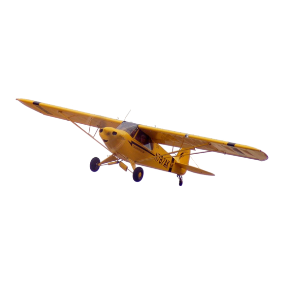
CUB CRAFTERS
CC11-100
CUB CRAFTERS, INC.
CC11-100 PILOT'S OPERATING HANDBOOK
AND FLIGHT TRAINING SUPPLEMENT
Airplane Serial Number:
Airplane Registration Number:
This airplane is approved as a special light-sport category
aircraft (S-LSA) as defined by 14CFR§1.1 and meets the
requirements of ASTM consensus standard F2245. This
document must be carried in the airplane at all times.
CUB CRAFTERS, INC.
1918 S 16th Avenue,
Yakima WA. 98903 USA
Website:
www.cubcrafters.com
Email:
support@cubcrafters.com
REPORT SC10000AFM
Issued: 08/01/06
Date of Revision: 11/23/18
Page Number: 0-i
Advertisement
Chapters
Table of Contents

Related Manuals for Cub Crafters CC11-100


Summary of Contents for Cub Crafters CC11-100
- Page 1 CUB CRAFTERS CC11-100 CUB CRAFTERS, INC. CC11-100 PILOT’S OPERATING HANDBOOK AND FLIGHT TRAINING SUPPLEMENT Airplane Serial Number: Airplane Registration Number: This airplane is approved as a special light-sport category aircraft (S-LSA) as defined by 14CFR§1.1 and meets the requirements of ASTM consensus standard F2245. This document must be carried in the airplane at all times.
- Page 2 CUB CRAFTERS CC11-100 INTENTIONALLY LEFT BLANK REPORT SC10000AFM Issued: 08/01/06 Page Number: 0-ii Date of Revision: 11/23/18...
- Page 3 WITH THE AIRCRAFT IDENTIFIED ON THE FACE PAGE. ANY REVISIONS TO THIS MANUAL MUST BE INSERTED AS APPROPRIATE NOTE This document (SC10000AFM) is applicable to CC11-100 serial numbers CC11-00001 – CC11-00092. REPORT SC10000AFM Issued: 08/01/06 Date of Revision: 11/23/18 Page Number: 0-iii...
- Page 4 CUB CRAFTERS CC11-100 INTENTIONALLY LEFT BLANK REPORT SC10000AFM Issued: 08/01/06 Page Number: 0-iv Date of Revision: 11/23/18...
- Page 5 Welcome to the group of discriminating pilots that truly enjoy flying and have selected the Sport Cub. It is our aim at Cub Crafters to ensure that you get the most from your airplane. This manual has been prepared to provide you with information about your airplane's equipment, operating procedures, performance, and suggested care.
- Page 6 CUB CRAFTERS CC11-100 This manual has been prepared in accordance with consensus standard ASTM F 2746. The Sport Cub has been shown to comply with consensus standard ASTM F 2245. The airplane must be maintained in accordance with consensus standard ASTM F 2295, Standard Practice for Continued Operational Safety Monitoring of a Light Sport Aircraft.
- Page 7 CUB CRAFTERS CC11-100 LOG OF REVISIONS Current revisions to the CC11-100 Pilot’s Operating Manual and Flight Manual, Report SC10000AFM. Revision Revised Description of Number Sections Revision Manual created as SC10000AFM. Section 0 Revision to Handbook. Section 2 Table 2-2 for Oil Pressure and Oil Temperature Gauge Markings.
- Page 8 CUB CRAFTERS CC11-100 Revision Revised Description of Number Sections Revision Section 0 Revision to Handbook Section 1 Revised Introduction Added Performance Specifications Section 2 Added Stall Speeds. Removed “cold only” from Oil Pressure Red Radial Line. Corrected Oil Temperature. Added Max. Weight Options.
- Page 9 CUB CRAFTERS CC11-100 Revision Revised Description of Number Sections Revision Section 0 Revision to Handbook Section 1 Update to Figure 1-1. Section 2 Added IMC to 2.11 Section 3 Corrected Carburetor Heat Reference. Section 7 Revised fiberglass to composite or composite materials.
- Page 10 CUB CRAFTERS CC11-100 Revision Revised Description of Number Sections Revision K cont Section 4 Revised 4.3.1.1 Circuit Breakers Check and Moved Master Switch. Revised 4.3.1.2 “Cowling” to “Cowl”. Revised 4.3.3.6.1 for Closed Doors and Windows. Revised 4.4.1.1 for Circuit Breaker Locations.
- Page 11 CUB CRAFTERS CC11-100 List of Effective pages Page Change Date Prepared Checked Number Initial Issue 08/01/06 Log of Revisions. 10/19/07 Table 2-2 Log of Revisions. 01/28/08 Revised CAS to 2-1, 2-2, IAS. & 2-3 Table 2-2. Revised 2.12. Revised 2.14.
- Page 12 CUB CRAFTERS CC11-100 Page Change Date Prepared Checked Number Corrected Oil 11/26/08 Cont Temperature to 240°. Added Maximum Weight Options. Added ‘if equipped” to 2.10 and 2.13. Added Total Fuel Capacity. Corrected placard location. Revised 3.2. Removed “fully” 2-11 from 3.3.2.
- Page 13 CUB CRAFTERS CC11-100 Page Change Date Prepared Checked Number Log of Revisions 04/09/10 List of Effective Pages. Revised Figure 1- Added information to 2.11. 3-15 Corrected Carburetor Heat reference. Revised fiberglass to composite. Added AOSS. Removed "Optional". Revised fiberglass to composite materials.
- Page 14 CUB CRAFTERS CC11-100 Page Change Date Prepared Checked Number 3-13 Added 3.3.14 03/13/12 cont 3-28 Added 3.4.16 9-0-i Added Supplement 9.5 0-5 – 0-6 Log of Revisions 08/09/12 0-10 List of Effective Pages 2-1 – 2-8 Revised for converted units.
- Page 15 CUB CRAFTERS CC11-100 Page Change Date Prepared Checked Number Log of Revisions. 0-11 List of Effective Pages. 0-iii Added Serial Number Effectivity. Added Rec. Oil Qty. Revised Figure 1- Added Rec. Oil Qty. Separated Environmental Limitations by S- 11/23/18 LSA and E-LSA.
- Page 16 CUB CRAFTERS CC11-100 INTENTIONALLY LEFT BLANK REPORT SC10000AFM Issued: 08/01/06 Page Number: 0-12 Date of Revision: 11/23/18...
- Page 17 CUB CRAFTERS CC11-100 TABLE OF CONTENTS SECTION 1 GENERAL INFORMATION SECTION 2 LIMITATIONS SECTION 3 EMERGENCY PROCEDURES SECTION 4 NORMAL PROCEDURES SECTION 5 PERFORMANCE SECTION 6 WEIGHT AND BALANCE SECTION 7 AIRCRAFT AND SYSTEMS SECTION 8 HANDLING AND SERVICING SECTION 9...
- Page 18 CUB CRAFTERS CC11-100 INTENTIONALLY LEFT BLANK REPORT SC10000AFM Issued: 08/01/06 Page Number: 0-14 Date of Revision: 11/23/18...
- Page 19 CUB CRAFTERS SECTION 1 CC11-100 GENERAL INFORMATION TABLE OF CONTENTS SECTION 1 GENERAL INFORMATION Paragraph Page 1 GENERAL INFORMATION INTRODUCTION ......... 1-1 WARNING, CAUTIONS, AND NOTES ..1-1 SUMMARY OF PERFORMANCE SPECIFICATIONS ........1-3 REPORT SC10000AFM Issued: 08/01/06 Date of Revision: 11/23/18...
- Page 20 SECTION 1 CUB CRAFTERS GENERAL INFORMATION CC11-100 INTENTIONALLY LEFT BLANK REPORT SC10000AFM Issued: 08/01/06 Page Number: 1-ii Date of Revision: 11/23/18...
- Page 21 CUB CRAFTERS SECTION 1 CC11-100 GENERAL INFORMATION GENERAL INFORMATION INTRODUCTION This Pilot’s Operating Handbook contains information required by the FAA and ASTM at the time the aircraft was certified. It also has additional data which Cub Crafters, based on its experience, has found useful.
- Page 22 GENERAL INFORMATION CC11-100 The owner is reminded that it is her/his responsibility to ensure that Cub Crafters has the appropriate contact information so that flight safety and other important information can be communicated in a timely manner. WARNINGS, CAUTIONS, AND NOTES...
- Page 23 CUB CRAFTERS SECTION 1 CC11-100 GENERAL INFORMATION 1.3 SUMMARY OF PERFORMANCE SPECIFICATIONS Gross Weight (wheels or skis) ......1320 lbs Gross Weight (floats) ........1430 lbs Top Speed (Sea Level/100hp) ......122 mph Cruise Speed (6000’, 75%) ......99 mph Range (6000’, 75%, w/reserves) ......
- Page 24 SECTION 1 CUB CRAFTERS GENERAL INFORMATION CC11-100 Figure 1-1 Three View Drawing REPORT SC10000AFM Issued: 08/01/06 Page Number: 1-4 Date of Revision: 11/23/18...
- Page 25 CUB CRAFTERS SECTION 1 CC11-100 GENERAL INFORMATION Figure 1-2 Turning Radius REPORT SC10000AFM Issued: 08/01/06 Date of Revision: 11/23/18 Page Number: 1-5...
- Page 26 SECTION 1 CUB CRAFTERS GENERAL INFORMATION CC11-100 INTENTIONALLY LEFT BLANK REPORT SC10000AFM Issued: 08/01/06 Page Number: 1-6 Date of Revision: 11/23/18...
-
Page 27: Table Of Contents
CUB CRAFTERS SECTION 2 CC11-100 LIMITATIONS TABLE OF CONTENTS SECTION 2 LIMITATIONS Paragraph Page 2. LIMITATIONS 2.1 GENERAL ............2-1 2.2 AIRSPEED LIMITATIONS ....... 2-1 2.3 AIRSPEED INDICATOR MARKINGS ....2-3 2.4 POWERPLANT LIMITATIONS ......2-4 2.5 POWERPLANT INSTRUMENT MARKINGS ... 2-5 2.6 WEIGHT LIMITS .......... - Page 28 SECTION 2 CUB CRAFTERS LIMITATIONS CC11-100 INTENTIONALLY LEFT BLANK REPORT SC10000AFM Issued: 08/01/06 Page Number: 2-ii Date of Revision: 11/23/18...
-
Page 29: Limitations
SECTION 2 CC11-100 LIMITATIONS LIMITATIONS GENERAL This section provides the approved operating limitations, instrument markings, color-coding and basic placards for operation of the Cub Crafters CC11-100 aircraft. Limitations associated with optional systems equipment which requires handbook supplements can be found in Section 9 “Supplements”. - Page 30 SECTION 2 CUB CRAFTERS LIMITATIONS CC11-100 SPEED IAS (mph/kts) Maximum Flap Extended Speed (V First notch (15°)..........85/74 Second notch (35°)........81/70 Full flaps (50°)..........81/70 Do not exceed the flap speed corresponding to a given setting Maximum Demonstrated Crosswind Component ..........
-
Page 31: Airspeed Indicator Markings
CUB CRAFTERS SECTION 2 CC11-100 LIMITATIONS AIRSPEED INDICATOR MARKINGS Airspeed indicator markings and their significance are shown in Table 2-1. SPEED RANGE OR MARKING SIGNIFICANCE VALUE (IAS mph/kts) Red radial 141/122 Never exceed speed V line Operations must be 101-141/... -
Page 32: Powerplant Limitations
SECTION 2 CUB CRAFTERS LIMITATIONS CC11-100 POWERPLANT LIMITATIONS Engine manufacturer ......Teledyne Continental Engine model number ..........O-200A Engine operating limits Takeoff Power ..........100 bhp Maximum Engine Speed ......2750 rpm Oil Pressure, Minimum ........30 psi Oil Pressure, Maximum ......... 60 psi Oil Temperature, Maximum ...... -
Page 33: Powerplant Instrument Markings
CUB CRAFTERS SECTION 2 CC11-100 LIMITATIONS POWERPLANT INSTRUMENT MARKINGS Red radial line 2750 rpm TACHOMETER Green arc (normal 900-2750 rpm operating range) Yellow arc 10-30 psi (caution, low) Green arc 30-60 psi (normal) OIL PRESSURE Yellow arc 60-100 psi (caution, high) -
Page 34: Weight Limits
SECTION 2 CUB CRAFTERS LIMITATIONS CC11-100 WEIGHT LIMITS Maximum Weight (On Wheels or Skis) ..1320 lbs/600 kg Maximum Weight (On Floats) ..... 1430 lbs/650 kg CENTER OF GRAVITY Forward CG Limits At 1320 lbs/600 kg ..... 73.0 inches aft of datum At 1100 lbs/500 kg or less . -
Page 35: Minimum Flight Crew
CUB CRAFTERS SECTION 2 CC11-100 LIMITATIONS 2.10 MINIMUM FLIGHT CREW The minimum required flight crew is one pilot in the front seat. This does not preclude a qualified flight instructor giving dual instruction from the back seat, if equipped. 2.11 ENVIRONMENTAL LIMITATIONS S-LSA: Day V.F.R. -
Page 36: Allowable Fuel Loading
SECTION 2 CUB CRAFTERS LIMITATIONS CC11-100 2.14 ALLOWABLE FUEL LOADING Standard Configuration: 25.0 US gallons/94 Liters total capacity 24.0 US gallons/90 Liters total usable Extended Range Configuration: 44.0 US gallons/167 Liters total capacity 40.0 US gallons/150 Liters total usable 2.15 BAGGAGE AND CARGO LOADING... -
Page 37: Types Of Surfaces
CUB CRAFTERS SECTION 2 CC11-100 LIMITATIONS 2.17 TYPES OF SURFACES The aircraft may be operated from paved and unpaved runways. 2.18 VORTEX GENERATORS The aircraft is allowed to fly with the following number of vortex generators missing: • Not more than three vortex generators missing on an aircraft. -
Page 38: Placards
SECTION 2 CUB CRAFTERS LIMITATIONS CC11-100 2.19 PLACARDS In view of the pilot: OPERATOR MUST READ AND BE FAMILIAR WITH PILOT OPERATING HANDBOOK BEFORE FLYING AIRCRAFT. NO INTENTIONAL SPINS. READ THE PILOT'S OPERATING HANDBOOK. NO INTENTIONAL SPINS. FLIGHT INTO IMC PROHIBITED. - Page 39 CUB CRAFTERS SECTION 2 CC11-100 LIMITATIONS In forward cargo compartment: Next to fuel selector for standard tanks: Next to fuel selector for extended range tanks: REPORT SC10000AFM Issued: 08/01/06 Date of Revision: 11/23/18 Page Number: 2-11...
- Page 40 SECTION 2 CUB CRAFTERS LIMITATIONS CC11-100 In cargo shelf compartment: On extended baggage compartment door: On flap lever: On wing next to tank filler with standard tanks: REPORT SC10000AFM Issued: 08/01/06 Page Number: 2-12 Date of Revision: 11/23/18...
- Page 41 CUB CRAFTERS SECTION 2 CC11-100 LIMITATIONS On wing next to tank filler with extended range tanks: Near stall warning vane: On right-hand side of empennage: On open door jamb: Below each throttle control: REPORT SC10000AFM Issued: 08/01/06 Date of Revision: 11/23/18...
- Page 42 SECTION 2 CUB CRAFTERS LIMITATIONS CC11-100 Next to windows Right side of seat base*: *Only required for aircraft with both the Artex ELT and battery compartment insert installed. Located above the right fuel drain, left fuel drain*, and gascolator on cowl.
- Page 43 CUB CRAFTERS SECTION 3 CC11-100 EMERGENCY PROCEDURES TABLE OF CONTENTS SECTION 3 EMERGENCY PROCEDURES Paragraph Page EMERGENCY PROCEDURES ....... 3-1 3.1 GENERAL............3-1 3.2 AIRSPEEDS FOR EMERGENCY OPERATIONS3-2 3.3 EMERGENCY CHECKLIST ....... 3-3 3.3.1 ENGINE FIRE DURING START ....3-3 3.3.2...
- Page 44 SECTION 3 CUB CRAFTERS EMERGENCY PROCEDURES CC11-100 3.4.6 FIRE IN FLIGHT ........3-19 3.4.7 LOSS OF OIL PRESSURE ..... 3-20 3.4.8 HIGH OIL TEMPERATURE ....3-20 3.4.9 EMERGENCY DESCENT ....... 3-21 3.4.10 ALTERNATOR FAILURE ......3-23 3.4.11 OVERVOLTAGE ........3-24 3.4.12...
-
Page 45: Emergency Procedures
CUB CRAFTERS SECTION 3 CC11-100 EMERGENCY PROCEDURES EMERGENCY PROCEDURES GENERAL This section provides the recommended procedures that should be followed during an emergency or a critical situation. It is divided into two parts. The first contains emergency procedure checklists. The second part... -
Page 46: Airspeeds For Emergency Operations3-2
SECTION 3 CUB CRAFTERS EMERGENCY PROCEDURES CC11-100 AIRSPEEDS FOR EMERGENCY OPERATIONS KNOTS STALL SPEEDS Flaps up (V )........40 Flaps down (50°) (V )......32 OPERATING MANEUVERING SPEED (V At 1320 lb (On Wheels or Skis)....93 At 1430 lb (On Floats)......97 BEST GLIDE (V Flaps up (1320 lb)........68... -
Page 47: Emergency Checklist
CUB CRAFTERS SECTION 3 CC11-100 EMERGENCY PROCEDURES EMERGENCY CHECKLIST 3.3.1 ENGINE FIRE DURING START Starter ............. Crank engine Continue to get a start that would suck the flames and accumulated fire into the engine. If engine starts: Power ........1700 RPM for a few minutes Engine .... -
Page 48: Engine Failure During Takeoff
SECTION 3 CUB CRAFTERS EMERGENCY PROCEDURES CC11-100 3.3.2 ENGINE FAILURE DURING TAKEOFF PRIOR TO LIFT-OFF Maintain directional control Throttle ................ Idle Brakes ..........Apply as necessary Wing Flaps ............Retract Mixture .............. Idle cut-off Magneto Switches ............Off Master Switch ............... Off... -
Page 49: Loss Of Engine Power In Flight
CUB CRAFTERS SECTION 3 CC11-100 EMERGENCY PROCEDURES 3.3.3 LOSS OF ENGINE POWER IN FLIGHT KNOTS If at low altitude: Airspeed (best glide)....MAINTAIN 68 If altitude permits: Airspeed (best glide)....MAINTAIN 68 Fuel Selector .............. Both Mixture ............... Full rich Carburetor Heat ..........On (Hot) Magnetos .......... -
Page 50: Emergency Landing Without Engine Power
SECTION 3 CUB CRAFTERS EMERGENCY PROCEDURES CC11-100 3.3.4 EMERGENCY LANDING WITHOUT ENGINE POWER Locate suitable field. KNOTS Airspeed (Flaps up).......68 Seat Belts ..........Tight and secure When landing area is assured: Throttle ................ Idle Mixture ............Idle Cut-Off Flaps ............... As required Door ................ -
Page 51: Precautionary Landing With Engine Power
CUB CRAFTERS SECTION 3 CC11-100 EMERGENCY PROCEDURES 3.3.5 PRECAUTIONARY LANDING WITH ENGINE POWER Fuel Selector ..............Both Seat Belts .............. Fastened Mixture ................Set Flaps ................Set KNOTS Maximum speed first notch flaps (15°)...85 Maximum speed full flaps (>15°)....81 Trim ..............As required Speed .............. -
Page 52: Fire In Flight
SECTION 3 CUB CRAFTERS EMERGENCY PROCEDURES CC11-100 3.3.6 FIRE IN FLIGHT Source of fire ............. Locate ELECTRICAL FIRE Master Switch ............... Off Windows ..............Open Cabin Door ............... Open If source of fire is located and it is safe and practical: Fire Extinguisher .......... -
Page 53: Loss Of Oil Pressure
CUB CRAFTERS SECTION 3 CC11-100 EMERGENCY PROCEDURES ENGINE FIRE Fuel Selector ..............Off Throttle ................ Idle Mixture ............. Idle cut-off Cabin Heater ..............Off Airspeed ......Maintain the highest possible, within limitations Proceed with emergency descent (Section 3.3.9) and emergency landing without engine power (Section 3.3.4). -
Page 54: Alternator Failure
SECTION 3 CUB CRAFTERS EMERGENCY PROCEDURES CC11-100 3.3.10 ALTERNATOR FAILURE Alternator output failure may be indicated by the low voltage annunciator illuminating. The alternator circuit breaker may trip. Output failure may be the result of a mechanical failure of the alternator or breaking of the alternator belt. -
Page 55: Overvoltage
CUB CRAFTERS SECTION 3 CC11-100 EMERGENCY PROCEDURES 3.3.11 OVERVOLTAGE If the bus voltage rises above 15.3 volts, the voltage annunciator will illuminate. Master Switch ..............Off Wait one minute. Then, switch the master switch on and monitor voltage. If the annunciator illuminates again, turn the master switch off and plan to continue flight without electrical system. -
Page 56: Inadvertent Icing Encounter
SECTION 3 CUB CRAFTERS EMERGENCY PROCEDURES CC11-100 3.3.13 INADVERTENT ICING ENCOUNTER WARNING THIS AIRCRAFT IS NOT APPROVED FOR FLIGHT INTO KNOWN ICING. FLIGHT INTO KNOWN ICING CONDITIONS IS PROHIBITED. CAUTION Ice accumulation on the wings and other airframe components will greatly increase the stall speed of the airplane and result in unpredictable flight characteristics. -
Page 57: Uncommanded Trim Actuation
CUB CRAFTERS SECTION 3 CC11-100 EMERGENCY PROCEDURES 3.3.14 UNCOMMANDED TRIM ACTUATION Standard Trim Switch TRIM circuit breaker………………………………Off (Pull) REPORT SC10000AFM Issued: 08/01/06 Date of Revision: 11/23/18 Page number: 3-13... -
Page 58: Amplified Emergency Procedures
SECTION 3 CUB CRAFTERS EMERGENCY PROCEDURES CC11-100 AMPLIFIED EMERGENCY PROCEDURES 3.4.1 ENGINE FIRE DURING START Engine fires during starting may be caused by excessive use of the engine fuel primer. The first attempt to extinguish the fire should be to draw the excess fuel into the engine. -
Page 59: Engine Failure During Takeoff
CUB CRAFTERS SECTION 3 CC11-100 EMERGENCY PROCEDURES 3.4.2 ENGINE FAILURE DURING TAKEOFF If an engine failure occurs prior to lifting off, the pilot must ensure he maintains control of the aircraft and comes to a stop on the remainder of the runway. The items in the checklist are listed to provide added safety after a failure of this type. - Page 60 In case of a total loss of power, the best glide speed is 68 mph or 59 knots (IAS) with flaps up. The CC11-100 will glide 1.2 nautical miles for every 1000 feet of altitude loss. The rate of descent will be approximately 715 feet per minute.
- Page 61 CUB CRAFTERS SECTION 3 CC11-100 EMERGENCY PROCEDURES 3.4.4 EMERGENCY LANDING WITHOUT ENGINE POWER When you have located a suitable field, establish a spiral pattern around this field. Try to be at 1,000 feet above the field at the downwind position, to make a normal approach.
- Page 62 SECTION 3 CUB CRAFTERS EMERGENCY PROCEDURES CC11-100 If the landing site is very rough, there is a possibility that the aircraft may come to rest inverted. Should this occur, once the aircraft has come to a stop, open the cabin door (if you have not already done so).
-
Page 63: Fire In Flight
CUB CRAFTERS SECTION 3 CC11-100 EMERGENCY PROCEDURES 3.4.6 FIRE IN FLIGHT The presence of fire is noted through smoke, smell, and heat in the cabin. Electrical fires are often accompanied by an acrid smell of burning insulation. Engine fires are very rare. The procedures outlined in the checklist are very general and pilot judgment should be the determining factor in the action to be taken. -
Page 64: Loss Of Oil Pressure
SECTION 3 CUB CRAFTERS EMERGENCY PROCEDURES CC11-100 3.4.7 LOSS OF OIL PRESSURE More often than not, a loss of oil pressure will be gradual. If it is accompanied by an increase in oil temperature, it is a sign that there is a problem with the engine’s oil system and the aircraft should be landed as soon as practical, as the engine may stop suddenly. -
Page 65: Emergency Descent
CUB CRAFTERS SECTION 3 CC11-100 EMERGENCY PROCEDURES 3.4.9 EMERGENCY DESCENT An Emergency Descent should be initiated whenever a situation occurs at high altitude requiring a high rate of descent. This is done in order to minimize exposure of the crew and passengers to an uncontrolled fire or when... - Page 66 SECTION 3 CUB CRAFTERS EMERGENCY PROCEDURES CC11-100 WARNING IF DESCENT IS TO BE MADE USING FULL FLAPS, SLOW THE AIRPLANE TO 81 mph or 70 knots IAS PRIOR TO FLAP EXTENSION AND PRIOR TO STARTING THE DESCENT. EXCEEDING THE FLAP...
-
Page 67: Alternator Failure
CUB CRAFTERS SECTION 3 CC11-100 EMERGENCY PROCEDURES 3.4.10 ALTERNATOR FAILURE Alternator output failure can be caused by a mechanical failure of the alternator, a momentary over-voltage condition, or other reasons. A zero or negative reading on the ammeter (if installed), or less than 12.0V on the voltmeter (if installed), can... -
Page 68: Overvoltage
SECTION 3 CUB CRAFTERS EMERGENCY PROCEDURES CC11-100 3.4.11 OVERVOLTAGE With the engine running, the alternator is capable of raising the bus voltage to dangerously high levels. The voltage regulator limits the bus voltage to between 13.5 and 15.3 volts. If the bus voltage rises above 15.3 volts, the voltage annunciator will illuminate. -
Page 69: Inadvertent Icing Encounter
CUB CRAFTERS SECTION 3 CC11-100 EMERGENCY PROCEDURES 3.4.13 INADVERTENT ICING ENCOUNTER Icing conditions are very difficult to predict. Aviation weather services may predict light, moderate, or severe icing conditions at certain locations and altitudes and no icing will be encountered. At other times, icing conditions may not be forecast and any of the above levels of icing may occur. -
Page 70: Loss Of Primary Instruments
SECTION 3 CUB CRAFTERS EMERGENCY PROCEDURES CC11-100 If the engine continues to run rough, it may indicate that ice is accumulating on the propeller. It is also good practice to apply carburetor heat prior to and during an extended descent as a preventive measure. -
Page 71: Loss Of Flight Controls
CUB CRAFTERS SECTION 3 CC11-100 EMERGENCY PROCEDURES 3.4.15 LOSS OF FLIGHT CONTROLS Aileron or Rudder Failure (cable driven) In the event of failure of the rudder or ailerons, control may still be maintained with the remaining control surface. Plan to land as soon as practical on a runway or field that minimizes the crosswind component. - Page 72 SECTION 3 CUB CRAFTERS EMERGENCY PROCEDURES CC11-100 INTENTIONALLY LEFT BLANK REPORT SC10000AFM Issued: 08/01/06 Page Number: 3-28 Date of Revision: 11/23/18...
- Page 73 CUB CRAFTERS SECTION 4 CC11-100 NORMAL PROCEDURES TABLE OF CONTENTS SECTION 4 NORMAL PROCEDURES Paragraph Page NORMAL PROCEDURES INTRODUCTION ..........4-1 AIRSPEEDS FOR NORMAL OPERATIONS ... 4-1 NORMAL PROCEDURES CHECKLIST ..4-3 4.3.1 PREFLIGHT ..........4-3 4.3.1.1 Cockpit ............4-3 4.3.1.2 Nose Section ..........
- Page 74 SECTION 4 CUB CRAFTERS NORMAL PROCEDURES CC11-100 AMPLIFIED NORMAL PROCEDURES ..4-15 4.4.1 PREFLIGHT..........4-15 4.4.1.1 Cockpit ............4-15 4.4.1.2 Nose Section ..........4-16 4.4.1.3 Left Fuselage, Wing, and Landing Gear ..4-17 4.4.1.4 Empennage ..........4-18 4.4.1.5 Right Fuselage, Wing, and Landing Gear ... 4-18 4.4.1.6 General............
-
Page 75: Normal Procedures
NORMAL PROCEDURES NORMAL PROCEDURES INTRODUCTION This section describes the procedures that Cub Crafters recommends for the pilot to follow during normal operations of the aircraft. It is divided into two parts. The first has abbreviated checklists; these are in a format suitable for reference in the cockpit. - Page 76 SECTION 4 CUB CRAFTERS NORMAL PROCEDURES CC11-100 Figure 4-1 Walk around REPORT SC10000AFM Issued: 08/01/06 Page Number: 4-2 Date of Revision: 11/23/18...
-
Page 77: Normal Procedures Checklist
CUB CRAFTERS SECTION 4 CC11-100 NORMAL PROCEDURES NORMAL PROCEDURES CHECKLIST 4.3.1 PREFLIGHT 4.3.1.1 Cockpit • Flight controls ..... Free and correct operation • Master switch ............On • Trim ...... Check operation and set for takeoff (marked on empennage) •... -
Page 78: Nose Section
SECTION 4 CUB CRAFTERS NORMAL PROCEDURES CC11-100 NOTE If passenger seat will be unoccupied, secure seat harness to prevent it from interfering with the flight controls or the pilot during flight. 4.3.1.2 Nose Section • Cowl ..............Secure • Cowl Flaps (if installed) ........Secure •... -
Page 79: Left Fuselage, Wing And Landing Gear
CUB CRAFTERS SECTION 4 CC11-100 NORMAL PROCEDURES 4.3.1.3 Left Fuselage, Wing and Landing Gear • Chocks ............Remove • Tire ..............Check • Brakes and Lines ..........Check • Main Landing Gear Leg and Strut ....Check • Fuel Tank ........... Check quantity •... -
Page 80: Empennage
SECTION 4 CUB CRAFTERS NORMAL PROCEDURES CC11-100 4.3.1.4 Empennage • Bracing Wires and Attach Brackets . Check for tension • Hinges ............... Check • Rudder Cables ........... Check • Beacon and Position Light (if installed) ..... Check • Control Surfaces ..........Check •... -
Page 81: Right Fuselage, Wing And Landing Gear
CUB CRAFTERS SECTION 4 CC11-100 NORMAL PROCEDURES 4.3.1.5 Right Fuselage, Wing and Landing Gear • Right Fuselage ..........Check • Fuel Sump (under fuselage) ......Drain • Flap Surface ........Check Condition • Flap Hinges ............. Check • Aileron Surface ........ Check Condition •... -
Page 82: Fuel Selector
SECTION 4 CUB CRAFTERS NORMAL PROCEDURES CC11-100 4.3.2 STARTUP AND TAXI 4.3.2.1 Before Starting Engine • Preflight Inspection ......... Complete • Seat Belts ............Fastened • Passenger Briefing ......... Complete • Parking Brakes (on master cylinders) .. Both wheels, set •... -
Page 83: Mixture
CUB CRAFTERS SECTION 4 CC11-100 NORMAL PROCEDURES 4.3.2.2 Starting Engine • Master Switch ............On • Mixture ............Full rich • Primer .............. Apply* • Throttle ..........Open 1/2 inch • Starter ............Engage After engine has started: • Oil Pressure ............. Check •... -
Page 84: Flaps
SECTION 4 CUB CRAFTERS NORMAL PROCEDURES CC11-100 4.3.2.4 Warm Up • Throttle ..........1000 to 1200 rpm 4.3.2.5 Taxiing • Parking Brakes (on master cylinders) ... Release both • Taxi Area ............Clear • Throttle ........... Apply slowly • Brakes .............. Check •... -
Page 85: Takeoff
CUB CRAFTERS SECTION 4 CC11-100 NORMAL PROCEDURES • Seat Belts ........... Check fastened • Brakes ............Release • Circuit Breakers (wing root) ......Check in • Circuit Breakers (seat base) ......Check in • Circuit Breakers (instrument panel) ....Check in •... - Page 86 SECTION 4 CUB CRAFTERS NORMAL PROCEDURES CC11-100 • Mixture ..............Adjust • Carburetor Heat ......... As required REPORT SC10000AFM Issued: 08/01/06 Page Number: 4-12 Date of Revision: 11/23/18...
-
Page 87: Approach And Landing
CUB CRAFTERS SECTION 4 CC11-100 NORMAL PROCEDURES 4.3.3.6 Approach and Landing 4.3.3.6.1 Normal Landing • Fuel Selector ............Both • Seat Belts ............Fastened • Mixture ..............Set • Flaps ................ Set INDICATED AIRSPEED (IAS) KNOTS Maximum speed first notch flaps (15°) Maximum speed (>15°) -
Page 88: Go-Around
SECTION 4 CUB CRAFTERS NORMAL PROCEDURES CC11-100 down, rudder and brakes to maintain directional control 4.3.3.7 Go-Around • Throttle ............ Full power • Carburetor Heat (if applicable) ......Off • Airspeed ..........Above 52 mph or 45 knots • Flaps ..........Retract slowly •... -
Page 89: Amplified Normal Procedures
CUB CRAFTERS SECTION 4 CC11-100 NORMAL PROCEDURES AMPLIFIED NORMAL PROCEDURES 4.4.1 PREFLIGHT 4.4.1.1 Cockpit Enter the cockpit and operate the flight controls to ascertain that they operate freely in the correct sense. As a rule of thumb, if the stick is moved towards a control surface, that surface must go up. -
Page 90: Nose Section
SECTION 4 CUB CRAFTERS NORMAL PROCEDURES CC11-100 operate the vane on the leading edge of the left wing with the master switch on. The stall horn should sound. After operating the electrical system, make sure that all circuit breakers are in. note that some are located on the left upper wing root, others on the forward part of the seat base and the instrument panel. -
Page 91: Left Fuselage, Wing, And Landing Gear
CUB CRAFTERS SECTION 4 CC11-100 NORMAL PROCEDURES Look through the air inlets on the front of the cowl and visually inspect the condition of the engine. Check the general condition of the exhaust system. Drain fuel from both the gascolator and the lower left drain (S/N 00264 and on), and inspect for water and sediment. -
Page 92: Empennage
SECTION 4 CUB CRAFTERS NORMAL PROCEDURES CC11-100 level in the wing tank and insure there are no obstructions in the vent tube. As you walk along the leading edge of the wing, look for dents, ensure that the tie downs have been removed, and gently operate the stall warning vane. -
Page 93: Startup And Taxi
CUB CRAFTERS SECTION 4 CC11-100 NORMAL PROCEDURES 4.4.2 STARTUP AND TAXI 4.4.2.1 Before Starting the Engine Adjust the pilot seat using the pins on the sides of the seat-base. The pins must be securely installed prior to flight. Adjust the straps to accommodate the passenger. -
Page 94: Warm Up
SECTION 4 CUB CRAFTERS NORMAL PROCEDURES CC11-100 throttle. Oil pressure should rise within 30 seconds; otherwise, shut the engine down. 4.4.2.4 Warm Up Before takeoff the engine should be warmed up for two to three minutes minimum, although longer may be required when the temperatures are below freezing. - Page 95 CUB CRAFTERS SECTION 4 CC11-100 NORMAL PROCEDURES Switch to the right magneto, noting the rpm, and turn back to both. The drop should not exceed 150 rpm on either magneto or show greater than a 75 rpm difference between magnetos.
- Page 96 SECTION 4 CUB CRAFTERS NORMAL PROCEDURES CC11-100 In hot and high conditions, especially above 3,000 feet, it is important to lean the mixture prior to the magneto check. To do this, apply full power. Slowly lean the mixture until you observe the peak RPM. Retard the throttle slowly and proceed with the rest of the run-up.
-
Page 97: Takeoff
CUB CRAFTERS SECTION 4 CC11-100 NORMAL PROCEDURES 4.4.3.2 Takeoff 4.4.3.2.1 Normal Takeoff The normal takeoff technique uses the first notch (15°) of flaps. Align on the runway and open the throttle. Maintain directional control at all times using appropriate rudder inputs. -
Page 98: Descent
SECTION 4 CUB CRAFTERS NORMAL PROCEDURES CC11-100 NOTE With a new engine, try to use 75% power as often as possible until either a total of 50 hours of operations have been accumulated or the oil consumption has stabilized. This will ensure that the piston rings seat correctly. - Page 99 CUB CRAFTERS SECTION 4 CC11-100 NORMAL PROCEDURES a smooth touchdown. Gradually bring the stick back, keeping it back throughout the landing roll. Maintain directional control with rudder and differential braking, as necessary. It is possible to settle the aircraft on the ground at higher speeds in a two-point configuration.
-
Page 100: Short Field Procedures
SECTION 4 CUB CRAFTERS NORMAL PROCEDURES CC11-100 NOTE It is recommended that a slightly higher airspeed be used on final approach during gusty or turbulent wind conditions. Add approximately one (1) mph or one (1) knot IAS for each two (2) knots of reported gust. -
Page 101: Balked Landing (Go-Around)
CUB CRAFTERS SECTION 4 CC11-100 NORMAL PROCEDURES 4.4.3.9 Balked Landing (Go-around) In a balked landing, apply full power. Slowly retract the flaps to the first notch (15°) and establish a positive rate of climb. Maintain climb speed. Trim as required. - Page 102 SECTION 4 CUB CRAFTERS NORMAL PROCEDURES CC11-100 INTENTIONALLY LEFT BLANK REPORT SC10000AFM Issued: 08/01/06 Page Number: 4-28 Date of Revision: 11/23/18...
- Page 103 CUB CRAFTERS SECTION 5 CC11-100 PERFORMANCE TABLE OF CONTENTS SECTION 5 PERFORMANCE Paragraph Page PERFORMANCE 5.1 INTRODUCTION ..........5-1 5.2 PERFORMANCE CHARTS ......5-3 5.2.1 AIRSPEED CALIBRATION ......5-4 5.2.2 STALL SPEED ...........5-5 5.2.3 TAKEOFF ...........5-7 5.2.4 CLIMB RATE AND GRADIENT ....5-9 5.2.5 CRUISE ............ 5-10 5.2.6 LANDING ..........
- Page 104 SECTION 5 CUB CRAFTERS PERFORMANCE CC11-100 INTENTIONALLY LEFT BLANK REPORT SC10000AFM Issued: 08/01/06 Page Number: 5-ii Date of Revision: 10/31/11...
-
Page 105: Introduction
CUB CRAFTERS SECTION 5 CC11-100 PERFORMANCE PERFORMANCE INTRODUCTION The purpose of this section is to provide information that will assist the pilot with planning a flight in detail with reasonable accuracy. All data has been corrected to I.C.A.O. standard day conditions. - Page 106 SECTION 5 CUB CRAFTERS PERFORMANCE CC11-100 The aircraft may be equipped with different tires and propellers. All of the data presented in this chapter are based on an aircraft equipped with the McCauley Propeller Systems model 1B90/CM7141 propeller and 8.50x6.00-6 tires.
- Page 107 CUB CRAFTERS SECTION 5 CC11-100 PERFORMANCE PERFORMANCE CHARTS Figure 5-1 Airspeed System Calibration ...... 5-4 Figure 5-2 Stall Speed versus Angle of Bank ....5-5 Figure 5-3 Takeoff Ground Distance ......5-7 Figure 5-4 Maximum Rate and Gradient of Climb ..5-9 Figure 5-5 Cruise Speed ...........
-
Page 108: Airspeed Calibration
SECTION 5 CUB CRAFTERS PERFORMANCE CC11-100 5.2.1 AIRSPEED CALIBRATION Indicated Airspeed (mph) Clean Ldg Flaps Figure 5-1 Airspeed System Calibration NOTE Indicated airspeed assumes zero instrument error. NOTE Airspeed indication can vary by several miles per hour depending on whether the fresh air vents and the door and windows are open or closed. -
Page 109: Stall Speed
CUB CRAFTERS SECTION 5 CC11-100 PERFORMANCE 5.2.2 STALL SPEED Angle of Bank (deg) Clean Landing Flaps Figure 5-2 Stall Speed versus Angle of Bank REPORT SC10000AFM Issued: 08/01/06 Date of Revision: 10/31/11 Page Number: 5-5... - Page 110 SECTION 5 CUB CRAFTERS PERFORMANCE CC11-100 INTENTIONALLY LEFT BLANK REPORT SC10000AFM Issued: 08/01/06 Page Number: 5-6 Date of Revision: 10/31/11...
-
Page 111: Takeoff
CUB CRAFTERS SECTION 5 CC11-100 PERFORMANCE 5.2.3 TAKE OFF 5.2.3.1 Normal takeoff Figure 5-3 Takeoff Ground Distance at 1320 lbs REPORT SC10000AFM Issued: 08/01/06 Date of revision: 10/31/11 Page number: 5-7... - Page 112 SECTION 5 CUB CRAFTERS PERFORMANCE CC11 Example: Takeoff conditions Outside air temperature (OAT) 60º F Pressure altitude at airport 4000 feet Aircraft weight 1250 lbs. Headwind 7 kts. On the graph at the furthest left of the chart, identify point A where the OAT intersects with the pressure altitude at the airport. Note the pressure altitude lines on the chart are at even thousands of feet.
-
Page 113: Climb Rate And Gradient
CUB CRAFTERS SECTION 5 CC11-100 PERFORMANCE 5.2.4 CLIMB RATE AND GRADIENT Pressure Climb Indicated Airspeed Altitude Gradient (°F) Knots (ft) 2000 59 °F Below 4000 Std Temp 6000 8000 2000 27°F Below 4000 Std Temp 6000 8000 2000 Std Temp... -
Page 114: Cruise
SECTION 5 CUB CRAFTERS PERFORMANCE CC11-100 5.2.5 CRUISE Pressure True Airspeed Fuel Flow Altitude Power (gph) Knots (ft) 1950 2150 2000 2350 2550 2750 1950 2150 4000 2350 2550 2750 1950 2150 6000 2350 2550 2750 1950 2150 8000 2350... -
Page 115: Landing
CUB CRAFTERS SECTION 5 CC11-100 PERFORMANCE 5.2.6 LANDING 5.2.6.1 Landing over 50’ obstacle Figure 5-6 Landing Distance over 50’ Obstacle REPORT SC10000AFM Issued: 08/01/06 Date of Revision: 10/31/11 Page Number: 5-11... - Page 116 SECTION 5 CUB CRAFTERS PERFORMANCE CC11 Example: Landing conditions Outside air temperature (OAT) 70 °F Pressure altitude at airport 2000 feet Aircraft weight 1200 lbs Headwind 10 kts On the graph at the furthest left of the chart, identify point A where the OAT intersects with the pressure altitude at the airport. Note the pressure altitude lines on the chart are at even thousands of feet.
-
Page 117: Balked Landing
CUB CRAFTERS SECTION 5 CC11-100 PERFORMANCE 5.2.7 BALKED LANDING Airspeed (IAS) Pressure Climb Altitude (ft) Gradient (%) KNOTS 4,000 Figure 5-7 Balked Landing Climb Gradient NOTE First notch flaps (15°) Mixture leaned for peak RPM REPORT SC10000AFM Issued: 08/01/06 Date of Revision: 10/31/11... -
Page 118: Glide
SECTION 5 CUB CRAFTERS PERFORMANCE CC11-100 5.2.8 GLIDE Statute Nautical Altitude Miles Miles Loss (ft) 1000 2000 3000 4000 5000 6000 7000 11.3 8000 12.8 11.1 9000 14.2 12.3 10000 15.6 13.6 11000 17.0 14.8 12000 18.4 16.0 13000 19.8 17.2... - Page 119 CUB CRAFTERS SECTION 6 CC11-100 WEIGHT AND BALANCE TABLE OF CONTENTS SECTION 6 WEIGHT AND BALANCE Paragraph Page WEIGHT AND BALANCE INTRODUCTION ..........6-1 6.2 PERTINENT INFORMATION FOR WEIGHT AND BALANCE ............6-2 6.2.1 TERMINOLOGY ........6-3 6.3 WEIGHING PROCEDURES ......6-5 6.3.1 PREPARATION ........6-5 6.3.2 LEVELING ..........6-6...
- Page 120 SECTION 6 CUB CRAFTERS WEIGHT AND BALANCE CC11-100 INTENTIONALLY LEFT BLANK REPORT SC10000AFM Issued: 08/01/06 Page Number: 6-ii Date of Revision: 10/31/11...
-
Page 121: Paragraph 6.6
CUB CRAFTERS SECTION 6 CC11-100 WEIGHT AND BALANCE WEIGHT AND BALANCE INTRODUCTION This section provides two very important pieces of information. Section 6.3 describes the methods for determining the empty weight of the aircraft and the position of the center of gravity relative to the datum. -
Page 122: Pertinent Information For Weight And Balance
SECTION 6 CUB CRAFTERS WEIGHT AND BALANCE CC11-100 The aircraft will perform as intended when it is properly loaded. Before it was delivered, the aircraft was weighed and the CG location was computed. You will find this information in Section 6.4. -
Page 123: Terminology
CUB CRAFTERS SECTION 6 CC11-100 WEIGHT AND BALANCE 6.2.1 TERMINOLOGY horizontal distance from the reference datum to the center of gravity (CG) of an item. Basic Empty Weight Standard empty weight plus optional equipment. Center of gravity (CG) The point at which an... - Page 124 SECTION 6 CUB CRAFTERS WEIGHT AND BALANCE CC11-100 Moment The product of the weight of an item multiplied by its arm. Maximum Takeoff Weight Maximum weight approved for the start of the takeoff run. Standard Empty Weight Weight standard airplane, including unusable fuel, full operating fluids and oil (5 qts).
-
Page 125: Weighing Procedures
CUB CRAFTERS SECTION 6 CC11-100 WEIGHT AND BALANCE WEIGHING PROCEDURES This procedure is to be followed for weighing the landplane. To weigh aircraft equipped with floats, consult the maintenance manual, document SC10000AMM. 6.3.1 PREPARATION Make sure that all of the equipment listed in the Aircraft Equipment List (Section 6.4) is installed and is in the... -
Page 126: Leveling
SECTION 6 CUB CRAFTERS WEIGHT AND BALANCE CC11-100 6.3.2 LEVELING Have a set of calibrated weighing scales available. The range should be 1000 lbs for each main and 250 lbs for the tail. Zero the scales or record the tare, as appropriate. - Page 127 CUB CRAFTERS SECTION 6 CC11-100 WEIGHT AND BALANCE Figure 6-1 Leveling the Aircraft Figure 6-2 Leveling the Aircraft REPORT SC10000AFM Issued: 08/01/06 Date of Revision: 10/31/11 Page Number: 6-7...
-
Page 128: Weighing
SECTION 6 CUB CRAFTERS WEIGHT AND BALANCE CC11-100 6.3.3 WEIGHING 1. Once the aircraft has been leveled, record the weight on the main wheels and the tailwheel. 261.90” Figure 6-3 Standard Aircraft Geometry * 59.50 for aircraft equipped with 3X3 landing gear. - Page 129 CUB CRAFTERS SECTION 6 CC11-100 WEIGHT AND BALANCE Standard Aircraft CG Calculation: × × 3X3 Landing Gear Equipped Aircraft CG Calculation: × × Where: CG Arm Distance from the datum to the center of gravity (in inches) Total weight of the aircraft...
- Page 130 SECTION 6 CUB CRAFTERS WEIGHT AND BALANCE CC11-100 INTENTIONALLY LEFT BLANK REPORT SC10000AFM Issued: 08/01/06 Page Number: 6-10 Date of Revision: 10/31/11...
-
Page 131: Weight And Balance Data And Record
Table 6-1 shows the following information at the time when the aircraft was licensed at the factory: Basic empty Weight Center of Gravity Useful Load MODEL CC11-100 Aircraft Serial Number: Registration Number: Date: Basic empty Moment (in∙lbs) weight (lbs) - Page 132 SECTION 6 CUB CRAFTERS WEIGHT AND BALANCE CC11-100 INTENTIONALLY LEFT BLANK REPORT SC10000AFM Issued: 08/01/06 Page Number: 6-12 Date of Revision: 10/31/11...
- Page 133 CUB CRAFTERS, INC. SECTION 6 CC11-100 WEIGHT AND BALANCE MODEL: SERIAL NUMBER REGISTRATION NUMBER PAGE NUMBER _______________ ____________ CC11-100 Running Basic Empty Weight Change Added (+) Weight Item Description of Article or Removed (-) Wt (lb.) Arm (in.) Moment Wt (lb.)
- Page 134 SECTION 6 CUB CRAFTERS WEIGHT AND BALANCE CC11-100 INTENTIONALLY LEFT BLANK Table 6-2 Weight and Balance Record REPORT SC10000AFM Issued: 08/01/06 Page Number: 6-14 Date of Revision: 10/31/11...
-
Page 135: Weight And Balance Determination For Flight
CUB CRAFTERS SECTION 6 CC11-100 WEIGHT AND BALANCE WEIGHT AND BALANCE DETERMINATION FOR FLIGHT In order to calculate the weight and balance of the aircraft: 1. Insert the respective loads in Table 6-3 or 6-4. 2. Multiply each load by its respective arm and note the moment. - Page 136 SECTION 6 CUB CRAFTERS WEIGHT AND BALANCE CC11-100 Moment Moment Item Weight (lbs) (in∙lbs) Arm (in) Aircraft Empty Fuel 83.90 Pilot 71.40 Passenger 96.08 Forward Cargo Compartment (100 lb max) 110.40 Extended Cargo Compartment (20 lb max) 134.40 TOTAL CG Station:...
- Page 137 CUB CRAFTERS SECTION 6 CC11-100 WEIGHT AND BALANCE REPORT SC10000AFM Issued: 08/01/06 Date of Revision: 10/31/11 Page Number: 6-17...
-
Page 138: Sample Weight And Balance Calculation
SECTION 6 CUB CRAFTERS WEIGHT AND BALANCE CC11-100 SAMPLE WEIGHT AND BALANCE CALCULATION This section will provide a sample weight and balance calculation using the methods given in paragraph 6.5. Moment Moment Item Weight (lbs) (in∙lbs) Arm (in) 72.28 63825.5 Aircraft Empty 10068.0... - Page 139 CUB CRAFTERS SECTION 6 CC11-100 WEIGHT AND BALANCE REPORT SC10000AFM Issued: 08/01/06 Date of Revision: 10/31/11 Page Number: 6-19...
- Page 140 SECTION 6 CUB CRAFTERS WEIGHT AND BALANCE CC11-100 INTENTIONALLY LEFT BLANK REPORT SC10000AFM Issued: 08/01/06 Page Number: 6-20 Date of Revision: 10/31/11...
- Page 141 CUB CRAFTERS SECTION 7 CC11-100 AIRCRAFT AND SYSTEMS TABLE OF CONTENTS SECTION 7 AIRCRAFT AND SYSTEMS Paragraph Page AIRCRAFT SYSTEM AND DESCRIPTION 7.1 INTRODUCTION ..........7-1 7.2 AIRFRAME ............7-1 7.3 LANDING GEAR ..........7-2 7.4 FLIGHT CONTROLS ......... 7-3 7.5 POWERPLANT ..........
- Page 142 SECTION 7 CUB CRAFTERS AIRCRAFT AND SYSTEMS CC11-100 INTENTIONALLY LEFT BLANK REPORT SC10000AFM Issued: 08/01/06 Page Number: 7-ii Date of Revision: 11/23/18...
-
Page 143: Aircraft System And Description
The tail brace wires should not be used for lifting or handling the aircraft on the ground. The fuselage, wings, empennage, and landing gear are covered with a polyester fiber treated with Cub Crafters’ SSC10000AFM Issued: 04/15/09... -
Page 144: Landing Gear
SECTION 7 CUB CRAFTERS AIRCRAFT AND SYSTEMS CC11-100 proprietary covering process, which provides excellent, durable finish. LANDING GEAR The aircraft has a conventional, or tailwheel, landing gear configuration. The main gear legs are made from welded steel tubing. Bungee cords on cabane struts provide shock absorption. -
Page 145: Flight Controls
CUB CRAFTERS SECTION 7 CC11-100 AIRCRAFT AND SYSTEMS FLIGHT CONTROLS The aircraft has conventional controls, operated with a control stick, rudder pedals, and actuated with cables. Pitch trim is accomplished via an electric servo which moves the leading edge of the horizontal stabilizer up and down, effectively changing the angle of incidence. -
Page 146: Powerplant
SECTION 7 CUB CRAFTERS AIRCRAFT AND SYSTEMS CC11-100 POWERPLANT 7.5.1 ENGINE The aircraft is powered by a Teledyne-Continental 200A engine. This is an air-cooled, four cylinder powerplant that is capable of delivering up to 100 hp at 2750 RPM. A throttle controls power to the engine. Each occupant is provided with a throttle on the left side of the cockpit. -
Page 147: Exhaust System
CUB CRAFTERS SECTION 7 CC11-100 AIRCRAFT AND SYSTEMS Some aircraft are equipped with ground adjustable cowl flaps on the lower cowl. Remove the lower cowl from the aircraft to adjust the flaps as necessary, ensuring all attachment fasteners are retightened. - Page 148 SECTION 7 CUB CRAFTERS AIRCRAFT AND SYSTEMS CC11-100 It is important that the pilot become knowledgeable about carburetor icing and the use of the carburetor heat. Cub Crafters recommends the following publication, available from the FAA website: Advisory Circular 20-113...
-
Page 149: Oil System
CUB CRAFTERS SECTION 7 CC11-100 AIRCRAFT AND SYSTEMS immediately before takeoff. DO NOT leave carburetor heat on for the actual takeoff. 7.5.8 OIL SYSTEM The oil system is an integral part of the engine, except for the cooler that is mounted on the lower, left-hand side of the firewall. - Page 150 SECTION 7 CUB CRAFTERS AIRCRAFT AND SYSTEMS CC11-100 Figure 2 - Standard Fuel Tank Configuration with Additional Fuel Drain (S/N 00264 and on) In the extended range configuration, there are two interconnected tanks on the inboard end of each wing.
- Page 151 CUB CRAFTERS SECTION 7 CC11-100 AIRCRAFT AND SYSTEMS Figure 4 - Extended Range Fuel Tank Configuration with Additional Fuel Drain (S/N 00264 and on) The tanks are made of aluminum. There are two drains for the entire aircraft. One is located underneath the fuselage on the right side of the cockpit;...
-
Page 152: Electical System
SECTION 7 CUB CRAFTERS AIRCRAFT AND SYSTEMS CC11-100 The engine may be operated on the Both, Left, or Right positions. However, the Both position is required for takeoff and landing. Fuel quantity is determined by two sight-gauges located on either side of the cockpit at the wing root. The ventilation of the tanks is through the forward facing vented fuel caps. -
Page 153: Stall Warning
CUB CRAFTERS SECTION 7 CC11-100 AIRCRAFT AND SYSTEMS 7.5.12 STALL WARNING The stall warning system is activated by a vane located on the leading edge of the left wing. As the aircraft approaches the stall, a horn will sound. The system is calibrated so that the horn will come on at least 6 mph or 5 knots above the stall speed. - Page 154 SECTION 7 CUB CRAFTERS AIRCRAFT AND SYSTEMS CC11-100 The aircraft seats two in a tandem configuration. All flight controls are within reach of the forward occupant, and therefore, the aircraft must be flown from this position. The aft occupant is provided with a control stick, rudder pedals, throttle and brakes for flight instruction.
- Page 155 CUB CRAFTERS SECTION 7 CC11-100 AIRCRAFT AND SYSTEMS When the rear seat is not in use, it can be stowed in the Sling Seat Holder. See the Aircraft Maintenance Manual Section 5.4.15. Disconnect the two cinched nylon straps holding the seat cross bar to the floor by unscrewing and pushing in on the screw.
- Page 156 SECTION 7 CUB CRAFTERS AIRCRAFT AND SYSTEMS CC11-100 Slide the cross bar out of the rear seat cross bar sleeves and the nylon straps. Remove the seat cushion from the rear seat. Fold the rear seat for stowage. See Figure 8.
-
Page 157: Instrument Panel
CUB CRAFTERS SECTION 7 CC11-100 AIRCRAFT AND SYSTEMS Figure 9 - Stowage in Sling Seat Holder The seat cross bar can either be securely stowed in the aft baggage compartment or reinstalled in the fuselage cross bar slots. If the cross bar is reinstalled, the nylon... -
Page 158: Baggage And Cargo Compartment
SECTION 7 CUB CRAFTERS AIRCRAFT AND SYSTEMS CC11-100 BAGGAGE AND CARGO COMPARTMENT The standard aircraft has a cargo compartment located behind the rear occupant that is divided into two areas. The forward area has a capacity of 100 lbs and the upper aft area 20 lbs. - Page 159 CUB CRAFTERS SECTION 8 CC11-100 HANDLING AND SERVICING TABLE OF CONTENTS SECTION 8 HANDLING AND SERVICING Paragraph Page 8 HANDLING AND SERVICING 8.1 INTRODUCTION ..........8-1 8.2 GROUND HANDLING .......... 8-1 8.2.1 TOWING INSTRUCTIONS ......8-1 8.2.2 TIE-DOWN INSTRUCTIONS ....... 8-1 8.3 SERVICING FUEL, OIL, AND OTHER FLUIDS ..
- Page 160 SECTION 8 CUB CRAFTERS HANDLING AND SERVICING CC11-100 INTENTIONALLY LEFT BLANK REPORT SC10000AFM Issued: 11/26/08 Page number: 8-ii Date of revision: 10/31/11...
-
Page 161: Handling And Servicing
CUB CRAFTERS SECTION 8 CC11-100 HANDLING AND SERVICING HANDLING AND SERVICING INTRODUCTION This section gives a description of the ground handling and basic servicing of the aircraft. GROUND HANDLING 8.2.1 TOWING INSTRUCTIONS The aircraft can be moved manually without the use of a tow bar. -
Page 162: Servicing Fuel, Oil, And Other Fluids
SECTION 8 CUB CRAFTERS HANDLING AND SERVICING CC11-100 SERVICING FUEL, OIL, AND OTHER FLUIDS 8.3.1 OIL Approved Oils: Cold Weather: SAE 20W-50 or SAE 15W-50 Warm Weather: SAE 40 or SAE 50 Approved Oil Filter: K&N HP1008 Mineral oil is used during the first 50 hours for engine break-in. -
Page 163: Brake Fluid
Cub Crafters Part Number SC54108-001 Visually inspect air filter. Depending on the operating conditions, filter life will vary. Monitor filter and obtain replacement from Cub Crafters when required. CLEANING AND CARE 8.4.1 EXTERIOR Use mild automotive soap for washing the exterior of the aircraft. - Page 164 SECTION 8 CUB CRAFTERS HANDLING AND SERVICING CC11-100 8.4.2 INTERIOR A damp rag is typically adequate for cleaning the interior of the aircraft. The windows and windshield can be cleaned using Zep Foaming Glass Cleaner. REPORT SC10000AFM Issued: 11/26/08 Page number: 8-4...
- Page 165 CUB CRAFTERS SECTION 9.0 CC11-100 SUPPLEMENTS TABLE OF CONTENTS SECTION 9 SUPPLEMENTS GENERAL STRAIGHT AND AMPHIBIOUS FLOATS ..9-1-1 SINGLE PLACE CONVERSION ....9-2-1 CONVERSION TABLES ....... 9-3-1 FORMS ............9-4-1 TWO-SWITCH ELEVATOR TRIM SYSTEM . 9-5-1 REPORT SC10000AFM Issued: 10/31/11...
- Page 166 SECTION 9.0 CUB CRAFTERS CC11-100 SUPPLEMENTS INTENTIONALLY LEFT BLANK REPORT SC10000AFM Issued: 10/31/11 Page Number 9-0-ii Date of Revision: 03/13/12...
-
Page 167: General
CUB CRAFTERS SECTION 9.0 CC11-100 SUPPLEMENTS 9.0 GENERAL This section provides information that amends certain limitations, procedures and data which are applicable to airplanes equipped with one or more of the optional systems. These systems are not part of the standard package. - Page 168 SECTION 9.0 CUB CRAFTERS CC11-100 SUPPLEMENTS INTENTIONALLY LEFT BLANK REPORT SC10000AFM Issued: 10/31/11 Page Number 9-0-iv Date of Revision: 03/13/12...
-
Page 169: Straight And Amphibious Floats
CUB CRAFTERS SECTION 9.1 CC11-100 SUPPLEMENT- FLOATS STRAIGHT AND AMPHIBIOUS FLOATS LOG OF REVISIONS Current revisions to the Pilot’s Operating Handbook and Flight Training Supplement Section 9.1. Pages Description of Revision Initial Release Added 1500A (Amphibious) information 9-1-1 Added Log of Revisions 9-1-22 Revised Section 9.1.7.4. - Page 170 SECTION 9.1 CUB CRAFTERS SUPPLEMENT-FLOATS CC11-100 INTENTIONALLY LEFT BLANK REPORT SC10000AFM Issued: 04/15/09 Page Number: 9-1-2 Date of Revision: 04/09/13...
- Page 171 CUB CRAFTERS SECTION 9.1 CC11-100 SUPPLEMENT- FLOATS 9.1.1 GENERAL This supplement must be attached to the Pilot’s Operating Handbook when floats are installed per the Equipment List supplied with the aircraft and listed in Section 6 of this manual. The information contained herein supplements or supersedes the Pilot’s Operating...
- Page 172 9.1.4.1 GENERAL This section provides the operating limitations, instrument markings, color-coding and basic placards for operation that are specific to the Cub Crafters' CC11-100 when equipped with floats. Please refer to Section 2 of this manual for the complete list of operating limitations, instrument markings, color- coding and basic placards for operation that are common to the landplane and seaplane.
- Page 173 CUB CRAFTERS SECTION 9.1 CC11-100 SUPPLEMENT- FLOATS 9.1.4.2 AIRSPEED LIMITATIONS INDICATED AIRSPEED (IAS) KNOTS Never exceed speed (V Operating maneuvering speed (V (at 1430 lb) Maximum Flap Speed (V flaps 50°) Best Rate of Climb Speed (V (at 1430 lb)
- Page 174 SECTION 9.1 CUB CRAFTERS SUPPLEMENT-FLOATS CC11-100 9.1.4.4 PLACARDS Locate near water rudder retraction handle stowage hook: Next to the water rudder retraction handle: On the landing gear handle (Amphibious Only): LANDING GEAR Near Fuel Selector Valve on the left interior panel...
- Page 175 CC11-100 SUPPLEMENT- FLOATS 9.1.5 EMERGENCY PROCEDURES 9.1.5.1 GENERAL This section provides the procedures Cub Crafters recommends should be followed when encountering an emergency or a critical situation as related specifically to operations when the floats are installed. For all other emergency procedures, refer to Section 3 of this manual.
- Page 176 SECTION 9.1 CUB CRAFTERS SUPPLEMENT-FLOATS CC11-100 9.1.5.2 AIRSPEEDS FOR EMERGENCY OPERATIONS STALL SPEEDS (1430 lb) INDICATED AIRSPEED (IAS) KNOTS Flaps up (V )........Flaps down (50°) (V )...... BEST GLIDE (V Flaps up (1430 lb)......9.1.5.3 EMERGENCY CHECKLIST 9.1.5.3.1 Emergency Landing on Water without...
- Page 177 CUB CRAFTERS SECTION 9.1 CC11-100 SUPPLEMENT- FLOATS 9.1.5.3.2 Emergency Landing on Land without Engine Power INDICATED AIRSPEED (IAS) KNOTS ▪ Approach (flaps up)....V Seat Belts ........Tight and secure Flaps ............. As required Gear (Amphibious Only) ......... Down ...
- Page 178 SECTION 9.1 CUB CRAFTERS SUPPLEMENT-FLOATS CC11-100 9.1.5.4 AMPLIFIED EMERGENCY PROCEDURES 9.1.5.4.1 Total Loss of Engine Power in Flight The aircraft with floats will glide 1.1 nautical miles for every 1000 feet of altitude loss. The rate of descent will be approximately 890 feet per minute. Most GPS devices have a “Direct to”...
- Page 179 SUPPLEMENT- FLOATS 9.1.6 NORMAL PROCEDURES 9.1.6.1 INTRODUCTION This section describes the procedures Cub Crafters recommends for the pilot to follow during normal operations of the aircraft on floats. It is divided into two parts. The first has abbreviated checklists; these are in a format suitable for reference in the cockpit.
- Page 180 SECTION 9.1 CUB CRAFTERS SUPPLEMENT-FLOATS CC11-100 9.1.6.4.1 Cockpit Preflight Flight Controls ....Free and correct operation Trim ....Check operation and set for takeoff Fuel Selector ........... Both Flaps..........Proper operation Fuel Gauges ..Sufficient fuel for intended flight (use level flight indications for float operation) ...
- Page 181 CUB CRAFTERS SECTION 9.1 CC11-100 SUPPLEMENT- FLOATS 9.1.6.4.2 Preflight Right Fuselage, Wing, and Float Right Fuselage ..........Check Fuel Sump ............Drain Flap Surface ........Check condition Flap Hinges ........... Check Aileron Surface ....... Check condition ...
- Page 182 SECTION 9.1 CUB CRAFTERS SUPPLEMENT-FLOATS CC11-100 9.1.6.4.4 Preflight Left Fuselage, Wing, and Float Float Hatches ..Cargo secure and hatches latched Main and Nose Gear (Amphibious Only) ..Check Float ..Check for damage and water accumulation (use bilge pump as necessary)
- Page 183 CUB CRAFTERS SECTION 9.1 CC11-100 SUPPLEMENT- FLOATS 9.1.6.4.5 Empennage Bracing Wires ......Check for tension Hinges ............Check Surfaces ............Check Ventral Fin ............. Check 9.1.6.4.6 Preflight General Check that all wings and other external surfaces are free from frost, ice or snow.
- Page 184 SECTION 9.1 CUB CRAFTERS SUPPLEMENT-FLOATS CC11-100 Lights ............ As required Avionics Master Switch ........On 9.1.6.4.9 Starting Engine When Flooded Magneto/Ignition Switches ......Both on Mixture ............ Idle cut-off Throttle ............. Full open Starter ............Engage When engine fires: ...
- Page 185 CUB CRAFTERS SECTION 9.1 CC11-100 SUPPLEMENT- FLOATS Mixture ............. Set* Magnetos/Ignition ........Check both NOTE: Drop not to exceed 150 RPM or 75 RPM differential between magnetos and no engine roughness. For electronic ignition, little or no drop will be noted.
- Page 186 SECTION 9.1 CUB CRAFTERS SUPPLEMENT-FLOATS CC11-100 9.1.6.4.15 Cruise Power ..............Adjust Mixture ..............Adjust Carburetor Heat ......Cold, use as required 9.1.6.4.16 Descent Power ..............Adjust Mixture ..........Richen as required Carburetor Heat .......... As required 9.1.6.4.17 Approach...
- Page 187 CUB CRAFTERS SECTION 9.1 CC11-100 SUPPLEMENT- FLOATS WARNING IF WHEELS ARE IN DOWN POSITION FOR A WATER LANDING (AMPHIBIOUS ONLY), THE AIRCRAFT WILL FLIP OVER. FOR ALL WATER LANDING, ENSURE WHEELS ARE UP (AMPHIBIOUS ONLY). 9.1.6.4.19 Cross Wind Landing ...
- Page 188 Should it be necessary to weigh the aircraft on floats, please consult the maintenance manual. 9.1.7.2 PERTINENT INFORMATION FOR WEIGHT AND BALANCE OF THE CC11-100 AIRCRAFT EQUIPPED WITH FLOATS Position of Datum ........60 inches ahead of wing leading edge Maximum Gross Weight .........
- Page 189 CUB CRAFTERS SECTION 9.1 CC11-100 SUPPLEMENT- FLOATS 9.1.7.3 DETERMINATION OF EMPTY WEIGHT The empty weight and the position of the center of gravity are recorded in Section 6 of this manual. The weight and moments of the floats are given in Table 9-1-1 and 9-1-2.
- Page 190 SECTION 9.1 CUB CRAFTERS SUPPLEMENT-FLOATS CC11-100 9.1.7.4 WEIGHT AND BALANCE DETERMINATION FOR FLIGHT In order to calculate the weight and balance of the aircraft: 1. Insert the respective loads in Table 9-1-3 or Table 9-1-4. 2. Multiply each load by its respective arm and note the moment.
- Page 191 (100 lb max) Extended cargo compartment 138.40 (60 lb max) Takeoff weight Table 9-1-4 –Weight and Balance Loading Form with Floats Extended Cargo Compartment CC11-100 CG Envelop CC11-100 CG Envelope 1450 78.5" at 1430 lbs 73.0" at 1430 lbs 1400 1350...
- Page 192 SECTION 9.1 CUB CRAFTERS SUPPLEMENT-FLOATS CC11-100 9.1.8 PERFORMANCE All values listed are at gross weight under standard sea level conditions. The following data is applicable only to the CC11-100. 9.1.8.1 CLIMB Pressure Rate of Altitude (ft) Climb Knots 1,000 1426...
-
Page 193: Single Place Conversion
CUB CRAFTERS SECTION 9.2 CC11-100 SUPPLEMENT- SINGLE PLACE CONVERSION SINGLE PLACE CONVERSION LOG OF REVISIONS Current revisions to the Pilot’s Operating Manual and Flight Manual Section 9.2. Pages Description of Revision Initial Release 9-2-1 Added Log of Revisions 9-2-6 Added Table 9-2-3 Updated to new format. - Page 194 SECTION 9.2 CUB CRAFTERS CC11-100 SUPPLEMENT- SINGLE PLACE CONVERSION INTENTIONALLY LEFT BLANK REPORT SC10000AFM Issued: 04/15/09 Page Number: 9-2-2 Date of Revision: 10/31/11...
- Page 195 CUB CRAFTERS SECTION 9.2 CC11-100 SUPPLEMENT- SINGLE PLACE CONVERSION 9.2.1 GENERAL This supplement describes the process and requirements for converting a two place aircraft to a single place aircraft and provides authorization to perform this conversion. In accordance with ASTM and FAA regulations, a two place 80hp S-LSA must weigh less than 902 pounds empty.
- Page 196 SECTION 9.2 CUB CRAFTERS CC11-100 SUPPLEMENT- SINGLE PLACE CONVERSION For Two Place Operation: Rear seat must be installed. Single Seat Placard must be removed Maximum empty weight per Section 9.2.2.2. 9.2.2.2 EMPTY WEIGHT INFORMATION The maximum empty weights as defined by ASTM and FAA regulations are as shown in the table below.
- Page 197 CUB CRAFTERS SECTION 9.2 CC11-100 SUPPLEMENT- SINGLE PLACE CONVERSION 9.2.3 CONVERSION PROCEDURES 9.2.3.1 FROM TWO PLACE TO SINGLE PLACE Remove or stow the rear seat. See Section 9.2.3.4.. Remove the rear stick and install the rear stick stub cover. Install placard on the instrument panel, overhead tube near the compass correction card, or in another conspicuous place.
- Page 198 SECTION 9.2 CUB CRAFTERS CC11-100 SUPPLEMENT- SINGLE PLACE CONVERSION Use the table below to determine the weight and loading for a single seat aircraft. Note that in the example below, the rear seat is shown as completely removed. If the seat is stowed and not removed, remove this from your calculations.
- Page 199 CUB CRAFTERS SECTION 9.2 CC11-100 SUPPLEMENT- SINGLE PLACE CONVERSION 9.2.3.4 INSTALLATION OF REAR STICK COVER 1. Loosen and remove the AN3 bolt, washers, and AN365 lock nut holding the rear stick into the rear stick stub. 2. For first time installation, remove floor fasteners...
- Page 200 SECTION 9.2 CUB CRAFTERS CC11-100 SUPPLEMENT- SINGLE PLACE CONVERSION 4. Move the front control stick through the full range of motion (including trim) and ensure there is no contact between the rear stick stub and the stick cover. 5. Adjust...
- Page 201 CUB CRAFTERS SECTION 9.2 CC11-100 SUPPLEMENT- SINGLE PLACE CONVERSION Rear Seat Cushion Left Side Fuselage Cross Bar Slot Rear Seat Cross Bar Sleeves Right Side Fuselage Cross Bar Slot Cross Bar Cross Bar Nylon Straps 3. Slide the cross bar out of the rear seat cross bar sleeves and the nylon straps.
- Page 202 SECTION 9.2 CUB CRAFTERS CC11-100 SUPPLEMENT- SINGLE PLACE CONVERSION 4. The seat cross bar can either be securely stowed in the aft baggage compartment or reinstalled in the fuselage cross bar slots. If the cross bar is reinstalled, the nylon straps must be reinstalled on the cross bar and attached to the floorboard in order to securely hold the seat cross bar in place.
-
Page 203: Conversion Tables
CUB CRAFTERS SECTION 9.3 CC11-100 SUPPLEMENT- CONVERSION TABLES 9.3 CONVERSION TABLES LOG OF REVISIONS Current revisions to the Pilot’s Operating Manual and Flight Manual Section 9.3. Pages Description of Revision Initial Release REPORT SC10000AFM Issued: 10/31/11 Date of Revision: N/A... - Page 204 SECTION 9.3 CUB CRAFTERS CC11-100 SUPPLEMENT- CONVERSION TABLES INTENTIONALLY LEFT BLANK REPORT SC10000AFM Issued: 10/31/11 Page Number: 9-3-2 Date of Revision: N/A...
- Page 205 CUB CRAFTERS SECTION 9.3 CC11-100 SUPPLEMENT- CONVERSION TABLES 9.3.1 WEIGHT POUNDS INTO KILOGRAMS LIVRES EN KILOGRAMMES 0.454 0.907 1.361 1.814 2.268 2.722 3.175 3.629 4.082 4.536 4.990 5.443 5.897 6.350 6.804 7.257 7.711 8.165 8.618 9.072 9.525 9.979 10.433 10.886 11.340...
- Page 206 SECTION 9.3 CUB CRAFTERS CC11-100 SUPPLEMENT- CONVERSION TABLES INCHES INTO CENTIMETERS POUCES EN CENTIMETRES 10.2 12.7 15.2 17.8 20.3 22.9 25.4 27.9 30.5 33.0 35.6 38.1 40.6 43.2 45.7 48.3 50.8 53.3 55.9 58.4 61.0 63.5 66.0 68.6 71.1 73.7 76.2...
- Page 207 CUB CRAFTERS SECTION 9.3 CC11-100 SUPPLEMENT- CONVERSION TABLES 9.3.4 TEMPERATURE FAHRENHEIT INTO CELSIUS FAHRENHEIT EN CELSIUS °F °C °C °C °C °C °C °C °C °C °C -17.20 -16.7 -16.10 -15.60 -15.00 -14.40 -13.90 -13.30 -12.80 -12.20 -11.70 -11.10 -10.60 -10.00...
- Page 208 SECTION 9.3 CUB CRAFTERS CC11-100 SUPPLEMENT- CONVERSION TABLES 9.3.6 SPEED MILES PER HOUR INTO KNOTS knots knots knots knots knots knots knots knots knots knots 10.4 11.3 12.2 13.0 13.9 14.8 15.6 16.5 17.4 18.2 19.1 20.0 20.9 21.7 22.6 23.5...
-
Page 209: Forms
CUB CRAFTERS SECTION 9.4 CC11-100 SUPPLEMENT- FORMS FORMS LOG OF REVISIONS Current revisions to the Pilot’s Operating Handbook and Flight Training Supplement Section 9.4. Pages Description of Revision Initial Release REPORT SC10000AFM Issued: N/A Date of Revision: 10/31/11 Page Number: 9-4-1... - Page 210 SECTION 9.4 CUB CRAFTERS CC11-100 SUPPLEMENT- FORMS INTENTIONALLY LEFT BLANK REPORT SC10000AFM Issued: 04/15/09 Page Number: 9-4-2 Date of Revision: 10/31/11...
- Page 211 CUB CRAFTERS SECTION 9.4 CC11-100 SUPPLEMENT- FORMS 9.4.1 CHANGE OF ADDRESS / OWNERSHIP REPORT SC10000AFM Issued: N/A Date of Revision: 10/31/11 Page Number: 9-4-3...
- Page 212 SECTION 9.4 CUB CRAFTERS CC11-100 SUPPLEMENT- FORMS INTENTIONALLY LEFT BLANK REPORT SC10000AFM Issued: 04/15/09 Page Number: 9-4-4 Date of Revision: 10/31/11...
- Page 213 CUB CRAFTERS SECTION 9.4 CC11-100 SUPPLEMENT- FORMS 9.4.2 CONTINUED OPERATIONAL SAFETY REPORTING REPORT SC10000AFM Issued: N/A Date of Revision: 10/31/11 Page Number: 9-4-5...
- Page 214 SECTION 9.4 CUB CRAFTERS CC11-100 SUPPLEMENT- FORMS INTENTIONALLY LEFT BLANK REPORT SC10000AFM Issued: 04/15/09 Page Number: 9-4-6 Date of Revision: 10/31/11...
- Page 215 CUB CRAFTERS SECTION 9 CC11-100 SUPPLEMENTS- TWO-SWITCH ELEVATOR TRIM SYSTEM 9.5.1 TWO-SWITCH ELEVATOR TRIM SYSTEM LOG OF REVISIONS Pages Description of Revision Initial Release Issued: 03/13/12 REPORT SSC100000AFM Date of revision: N/A Page number 9-5-1...
- Page 216 SECTION 9 CUB CRAFTERS SUPPLEMENTS- TWO-SWITCH CC11-100 ELEVATOR TRIM SYSTEM INTENTIONALLY LEFT BLANK REPORT SSC100000AFM Issued: 03/13/12 Page number 9-5-2 Date of revision N/A...
- Page 217 CUB CRAFTERS SECTION 9 CC11-100 SUPPLEMENTS- TWO-SWITCH ELEVATOR TRIM SYSTEM 9.5.2 GENERAL This supplement must be attached to the Pilot’s Operating Handbook when an additional switch is added to the aft control stick to operate the Two-Switch Elevator Trim System.
- Page 218 SECTION 9 CUB CRAFTERS SUPPLEMENTS- TWO-SWITCH CC11-100 ELEVATOR TRIM SYSTEM Figure 1 Switches on control sticks Figure 2 Trim Selector Switch REPORT SSC100000AFM Issued: 03/13/12 Page number 9-5-4 Date of revision N/A...
- Page 219 CUB CRAFTERS SECTION 9 CC11-100 SUPPLEMENTS- TWO-SWITCH ELEVATOR TRIM SYSTEM 9.5.3 LIMITATIONS PLACARD 9.5.4 EMERGENCY PROCEDURES INADVERTENT ELEVATOR TRIM MOVEMENT Trim selector switch ............Off Should the elevator trim system begin to move without being operated intentionally, switch the selector switch on the left wing root panel to the OFF position (middle position Figure 2).
- Page 220 6 of the Pilot’s Operating Handbook. If it was retrofitted to the aircraft, the installation instructions provided by Cub Crafters will have the appropriate weight information that should be included in section 6 of the Pilot’s Operating Handbook 9.5.8...
- Page 221 CUB CRAFTERS SECTION 9 CC11-100 SUPPLEMENTS- TWO-SWITCH ELEVATOR TRIM SYSTEM The switch should normally be kept in the FRONT position to avoid inadvertent operation by an occupant in the aft seat. Similarly, if the switch is in the REAR position, operation by the aft occupant will take priority over operation by the forward occupant.
- Page 222 SECTION 9 CUB CRAFTERS SUPPLEMENTS- TWO-SWITCH CC11-100 ELEVATOR TRIM SYSTEM INTENTIONALLY LEFT BLANK REPORT SSC100000AFM Issued: 03/13/12 Page number 9-5-8 Date of revision N/A...